GAS COOKTOP INSTALLATION INSTRUCTIONS INSTALLATION AND SERVICE MUST BE PERFORMED BY A QUALIFIED INSTALLER. IMPORTANT: SAVE FOR LOCAL ELECTRICAL INSPECTOR'S USE. READ AND SAVE THESE INSTRUCTIONS FOR FUTURE REFERENCE. PSOE Te] If the information in this manual is not followed exactly, a fire or explosion may result causing property damage, personal injury or death.
GAS COOKTOP INSTALLATION INSTRUCTIONS Important Notes to the Installer 1. a) 2. Read all instructions contained in these installation instructions before installing the cooktop. Remove all packing material before connecting the electrical supply to the cooktop. Observe all governing codes and ordinances. Be sure to leave these instructions with the consumer. 5. Note: For operation at 2000 ft. elevations above see level, appliance rating shall be reduced by 4 percent for each additional 1000 ft.
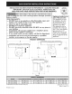
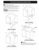
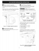
GAS COOKTOP INSTALLATION INSTRUCTIONS 30" (76.2 cm) Min. Clearance Between the Top of the Cooking Platform ni 13" (33 cm) | and Unprotected Wood or Metal NN Cabinet Max. Depth For Cabinet Installed Above Cooktop. Clearance 1 ¥8" (3.5 cm) Minimum Flat Distance from Cutout Edge. 1 34" (3.5 cm) Minimum Flat Distance from Cutout Edge. Figure 2 — CABINET MODEL 30" Cooktop 36" Cooktop co Te et Minimum Side Clearance 30" (76.2 cm) 36" (91.4 cm} | E Minimum Clearance from Each Side 9" (22.
GAS COOKTOP INSTALLATION INSTRUCTIONS Required Tools for Installation ~ Phillips Screwdriver - Ya" Nut driver / Ratchet - 7/6" Nut driver / Ratchet Supplied Hardware Qty. (4) Description (S)) (2) (au (6) Caw Used for the Hot nat CACC Blower (fig. 20} Tee Philips 1) fm: AEJE Wie ead (2) > Ve Hoe ead Screw (fig.
GAS COOKTOP INSTALLATION INSTRUCTIONS 3) LP/Propane Gas Conversion This appliance can be used with Natural gas or LP/ Propane gas. It is shipped from the factory for use with natural gas. A kit for converting to LP gas is supplied with your cooktop. The kit is marked "FOR LP/PROPANE GAS CONVERSION". The wall receptacle and circuit should be checked by a qualified electrician to make sure the receptacle is properly grounded.
GAS COOKTOP © INSTALLATION INSTRUCTIONS Installing the Ductwork Use galvanized or aluminum duct in 6” round or 314” x 10" size, or a combination of both. PVC duct should be used if installing under a poured concrete slab. Use the shortest and straightest duct run possible. For satisfactory performance, the duct run should not exceed 100 feet equivalent length. Refer to the “Calculating Duct Length” chart for equivalent lengths. (see page 14).
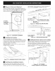
GAS COOKTOP INSTALLATION INSTRUCTIONS Preparing for Ductwork CENTER - CUTOUT Cut hole in cabinet wall or floor as appropriate for your installation. Make sure exhaust duct is located between wall studs or floor joists. Figure 9, 10, 11 & 12. NOTE: Ductwork MUST be vented to outside. DO NOT vent into a wall, ceiling, crawlspace, attic or any concealed space. When cutting or drilling into wall or ceiling, BO NOT damage electrical wiring and other hidden utilities.
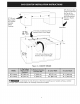
GAS COOKTOP INSTALLATION INSTRUCTIONS Blower to Ductwork Alignment the backside of the countertop. To prevent damage to the countertop, DO NOT overtighten the screw. The use of flexible ducting is discouraged because it can severely restrict airflow. If the blower outlet and the floor or wall duct location DO NOT align, then flexible METAL ducting can be used to adapt to an offset. rie | Down Two #8-18 Black Hex Head Screws Attached to Cooktop Bracket 6" MAX.
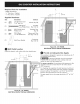
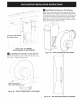
GAS COOKTOP INSTALLATION INSTRUCTIONS @ Installing the blower to the plenum e- —s/---—-— -\ 4 Install four nylon insert nuts to the studs on the blower, finger tighten until resistance is felt. Position the blower discharge opening to match the ductwork. Slide the nuts on the side of the blower housing into the four keyhole openings on the side of the plenum and allow to slide down into the slots. Using a wrench or ratchet from the inside of the plenum tighten the nuts.
GAS COOKTOP © Blower INSTALLATION INSTRUCTIONS electrical connection Connect the 5-pin plug on the blower assembly to the matching 5-pin receptacle on the bottom of the cooktop. Fold all wires into the wire box on the end of the blower conduit. Fasten the wire box to the cooktop with two #8 x 3/8” making sure that no wires are trapped.
GAS COOKTOP INSTALLATION INSTRUCTIONS TNIV Tie The supply line must be equipped with an approved manual shutoff valve. This valve should be located in the same room as the cooktop and should be in a location that allows ease of opening and closing. DO NOT block access to the shutoff valve. The valve is for turning on or shutting off gas to the appliance. © Electrical Requirements 120 volt, 60 Hertz, properly grounded branch circuit protected by a 15 amp circuit breaker or time delay fuse.
GAS COOKTOP & O A. B. INSTALLATION INSTRUCTIONS Install Burner Caps Unpack the burner grates. Burners: Unpack the Burner heads and burner caps. Place the burner heads and caps on the matching bases. The caps should be level after installation Be sure that all the burner caps burner head are correctly placed BEFORE using your cooktop 21) Install Filter and Carefully place vent grate seal over the vent chamber on the cooktop, with the side marked FRONT to the front.
GAS COOKTOP @ INSTALLATION INSTRUCTIONS When Ail Hookups are Complete Check Operation Make sure all controls are left in the OFF position. Refer to the Use and Care Guide packaged with the cooktop for operating instructions and for care and cleaning of your cooktop. Make Oi Turn on Electrical Power and Open Main Shutoff Gas Valve Read the Before You Call for Service Checklist and operating instructions in your Use and Care Guide. lt may save you time and expense.
GAS COOKTOP INSTALLATION INSTRUCTIONS Calculating Duct Length Table For maximum efficiency, use the shortest and straightest duct possible. Use as few fittings as possible. For best performance, the duct run should not exceed 100 feet of equivalent length. Calculations are approximate and based on HVAC industry standards. DUCT PIECES 6" (1§.2cm) Round (_) Straight ** Oo) 6" (15.2cm} Round Metal Flex No Bends #* 6" (15.2cm) QD) 90° Elbow 6" (15.
INSTRUCCIONES PARA LA INSTALACION DE LA PLANCHA DE COCINAR A GAS TODA TAREA DE INSTALACION O MANTENIMIENTO DEBERA REALIZARLA UN INSTALADOR CUALIFICADO. IMPORTANTE: GUARDE ESTAS INSTRUCCIONES PARA EL INSPECTOR LOCAL DE ELECTRICIDAD. LEA Y GUARDE ESTAS INSTRUCCIONES PARA FUTURAS CONSULTAS. Veen Si no sigue las instrucciones recogidas en este manual al pie de la letra se podria producir un incendio o una explosién que causaria dafios materiales, lesiones corporales o incluso la muerte.
INSTRUCCIONES PARA LA INSTALACION DE LA PLANCHA DE COCINAR A GAS Informacién importante para el instalador 1. 2. & 3. 5. Lea todas las instrucciones de instalacién suministradas antes de proceder a instalar la plancha. Retire todo el embalaje antes de conectar el suministro eléctrico al electrodoméstico. Tenga en cuenta la normativa y los cédigos locales. Asegutrese de dejar estas instrucciones al propietario.
INSTRUCCIONES PARA LA INSTALACION DE LA PLANCHA DE COCINAR A GAS 30" (76,2 cm) Espacio minimo entre la plancha y el mueble de metal o de madera no protegida =e 13" (33 cm) _ | Profundidad max. wN | del mueble situado sobre la plancha. Espacio 13" (3,5 cm) Distancia minima entre el hueco y el borde. 1%" (3,5 cm) Distancia minima entre el hueco y Figura 2 — DISENO MODELO Plancha de 30” Plancha de 36” E Fcc lat ie del mueble superior 30" (76,2 cm) 36" (91,4 cm} el borde.
INSTRUCCIONES PARA LA INSTALACION DE LA PLANCHA DE COCINAR A GAS Herramientas necesarias para la instalacién G - Destornillador Phillips | - ¥4" Llave para tuercas / trinquete - “he Llave para tuercas / trinquete 3 1/4” Elementos suministrados Cantidad (4) a Descripcién @) KO 1/4-20 Uso tuercas de cabeza Ventilador (een cabeza \\Ubicacion raco- mendada para el (fig. 20) \ tubo del suminis- 5 " .
INSTRUCCIONES PARA LA INSTALACION DE LA PLANCHA DE COCINAR A GAS e Péngase en contacto con un electricista cualificado para comprobar el circuito y que la toma de corriente de pared Conversién a gas propano/LP Este electrodoméstico ha sido disefiado para utilizar gas natural o gas propano. Los valores predeterminados de fdbrica se han establecido para su uso con gas natural. Con este producto se suministra un kit para la conversion a gas propano. El kit se titula "PARA CONVERSION PROPANO/LP".
© Instalacién del conducto de ventilacién Utilice un conducto galvanizado o de alumino | ee | INSTRUCCIONES PARA LA INSTALACION DE LA PLANCHA DE COCINAR A GAS redondo un conducto de PVC si va a instalarlo bajo una losa de hormig6n. Intente que el conducto recorra el tramo mds corto y mas recto posible. Para un rendimiento dptimo, el conducto no deberia exceder los cien pies de longitud.
INSTRUCCIONES PARA LA INSTALACION DE LA PLANCHA DE COCINAR A GAS Instalacién del conducto CENTRO HUECO de ventilacién Haga un orificio en la pared del mueble o dependiendo de lo que sea mds adecuado instalacién en particular. Asegdrese de que extractor esta situado entre un soporte en viga de soporte. Figura 9, 10, Il y 12. en el suelo, para su el conducto del la pared o una CENTRO HUECO DEL DEL NOTA: El conducto de ventilacién DEBE desembocar en el exterior.
INSTRUCCIONES PARA LA INSTALACION DE LA PLANCHA DE COCINAR A GAS © inferior de la encimera. Para evitar dafiar la encimera, NO apriete demasiado el tornillo. Alineacion del conducto de ventilacién y el ventilador No se recomienda el uso de conductos flexibles pues podrian impedir el fujo de aire. Si la salida del ventilador y la ubicacién del conducto en la pared o en el suelo NO estan alineadas, podria utilizar conductos flexibles de METAL para favorecer la nivelacién.
INSTRUCCIONES PARA LA INSTALACION DE LA PLANCHA DE COCINAR A GAS @ Union del ventilador a la camara Instale cuatro tuercas con insertos de nilén en los soportes del ventilador, ajustelos lo maximo posible. Coloque el orificio de descarga del ventilador de forma que coincida con el conducto de ventilacién. Deslice las tuercas en el lateral del ventilador de manera que encajen en los orificios en el lateral de la c4mara y deslicelas en las ranuras.
INSTRUCCIONES PARA LA INSTALACION DE LA PLANCHA DE COCINAR A GAS © Conexion eléctrica del ventilador Conecte los cinco polos del conjunto del ventilador en el receptdculo con cinco entradas en la parte inferior de la plancha. Doble los cables y gudrdelos dentro de la caja al final del tubo del ventilador. Asegure la caja de cableado a la plancha con dos tornillos #8 x 3/8", asegirese de no aprisionar ningén cable.
INSTRUCCIONES PARA LA INSTALACION DE LA PLANCHA DE COCINAR A GAS © y Ween EI tubo de suministro de gas debe incluir una vdlvula de cierre manual certificada. Esta valvula debe estar ubicada en la misma habitacién que la plancha de coninar en un lugar que facilite la apertura y el cierre. NO bloqueé el acceso a la valvula de cierre. La vdlvula sirve para abrir o cerrar el paso de gas al electrodoméstico.
INSTRUCCIONES PARA LA INSTALACION DE LA PLANCHA DE COCINAR A GAS @ Instalacién de las tapas de los quemadores, A. B. Desembale las parrillas de los quemadores. GQuemadores: Desembale las cabezas y las tapas de los quemadores. Coloque las cabezas de los quemadores y C. D. Verifique que las tapas estan niveladas tras instalarlas. Asegurese de que todas las tapas y las cabezas de los quemadores estan correctamente situadas ANTES de poner la plancha en funcionamiento.
INSTRUCCIONES PARA LA INSTALACION DE LA PLANCHA DE COCINAR A GAS @ Consulte la Guia de uso y electrodoméstico si desea las instrucciones generales sugerencias de cuidado y Ea Cuando se hayan realizado todas las conexiones Compruebe el funcionamiento Asegtrese de que todos los mandos de control estdn en la posicién OFF. cuidado suministrada con este obtener mas informacién sobre de funcionamiento, asi como limpieza.
INSTRUCCIONES PARA LA INSTALACION DE LA PLANCHA DE COCINAR A GAS Tabla para calcular la longitud del conducto Para mejorar la eficiencia, intente que el conducto sea lo mds corto y el recorrido lo mds recto posible. Use el menor numero de uniones posible. Para un rendimiento dptimo, el conducto no deberia exceder los cien pies de longitud. Estos cdlculos son aproximados y estan basados en los estandares de la industria de la calefaccién, ventilacién y aire acondicionado.