
Installation guide


GAS
COOKTOP
INSTALLATION
INSTRUCTIONS
©
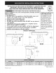
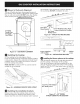
Blower
electrical
connection
Connect
the
5-pin
plug
on
the
blower
assembly
to
the
matching
5-pin
receptacle
on
the
bottom
of
the
cooktop.
Fold
all
wires
into
the
wire
box
on
the
end
of
the
blower
conduit.
Fasten
the
wire
box
to
the
cooktop
with
two
#8
x
3/8”
making
sure
that
no
wires
are
trapped.
Figure
21
—
CONNECT
BLOWER
TO
COOKTOP
®
Connecting
the
Ductwork
Connect
the
ductwork
prepared
in
Steps
8,
9
and
10
to
the
blower
transition
duct.
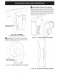
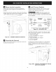
©
Install
Pressure
Regulator
Install
the
pressure
regulator
with
the
arrow
on
the
regulator
pointing
up
toward
the
unit
in
a
position
where
you
can
reach
the
access
cap.
&
WARNING
DO
NOT
make
the
connection
too
tight.
The
regulator
is
die
cast.
Overtightening
may
crack
the
regulator
resulting
in
a
gas
leak
and
possible
fire
or
explosion.
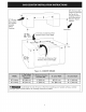
Manual
GAS
FLOW
Pressure
Shutoff
Flare
;
Flare
Regulator
Valve
Union
t
Flexible
Connector
Cap
All
connections
must
be
wrench-tightened
Figure
22
—
GAS
SUPPLY
LINE
Assemble
the
flexible
connector
from
the
gas
supply
pipe
to
the
pressure
regulator
in
the
following
order:
manual
shutoff
valve
1/2"
(1.3
cm)
nipple
1/2"
(1.3
cm}
flare
union
adapter
flexible
connector
1/2"
(1.3
cm}
flare
union
adapter
1/2"
(1.3
cm)
nipple
pressure
regulator
NOGRWON
>
Use
pipe-joint
compound
made
for
use
with
Natural
and
LP/Propane
gas
to
seal
all
gas
connections.
If
flexible
connectors
are
used,
be
certain
connectors
are
not
kinked.
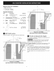
Figure
22B
—
PHYSICAL
ATTACHMENT
OF
THE
GAS
LINE
TO
THE
COOKTOP