
Installation guide


GAS
COOKTOP
INSTALLATION
INSTRUCTIONS
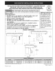
Required
Tools
for
Installation
~
Phillips
Screwdriver
-
Ya"
Nut
driver
/
Ratchet
-
7/6"
Nut
driver
/
Ratchet
Supplied
Hardware
Qty.
Description
Used
for
(4)
(S))
the
Hot nat
Blower
(fig.
20}
(2)
(au
CACC
Tee
Philips
Screw
(fig.
15
8
10)
1)
fm:
AEJE
Wie
ead
Yan
Di
(6)
Caw
Ve
Hoe
ead
Screw
bon
Wg
17
Be
o
(2)
Hold
Down
Bracket
Aas
8
te
>
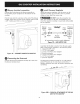
Wall
Outlet
Location
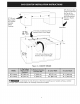
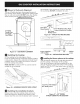
Install
the
electric
wall
outlet
within
the
shaded
area.
11
1/2”
(29.2
cm)
8
3/4”
Figure
3A
-
36”
MODEL
ELECTRICAL
OUTLET
INSTALL
DIMENSIONS
Figure
3B
-
30”
MODEL
ELECTRICAL
OUTLET
INSTALL
DIMENSIONS
&
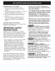
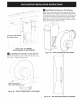
Provide
an
Adequate
Gas
Supply
This
cooktop
is
designed
to
operate
on
natural
gas
at
4”
of
manifold
pressure
only.
AA
WARNING
ES
pressure
regulator
must
be
connected
in
series
with
the
manifold
on
the
cooktop
and
must
remain
in
series
with
the
supply
line.
For
proper
operation,
the
maximum
inlet
pressure
to
the
regulator
must
be
no
more
than
14”
of
water
column
(W.C.}
pressure.
For
checking
the
regulator,
the
inlet
pressure
must
be
at
least
1"
(or
2.5
kPa)
greater
than
the
regulator
manifold
pressure
setting.
The
regulator
is
set
for
4"
of
manifold
pressure,
the
inlet
pressure
must
be
at
least
5”.
The gas
supply
line
to
the
range
should
be
1/2"
or
3/4"
pipe.