
Installation guide

INSTALLATION AND SERVICE MUST BE PERFORMED BY A QUALIFIED INSTALLER.
IMPORTANT: SAVE FOR LOCAL ELECTRICAL INSPECTOR'S USE.
READ AND SAVE THESE INSTRUCTIONS FOR FUTURE REFERENCE.
FOR YOUR SAFETY: Do not store or use gasoline or other flammable vapors and liquids in
the vicinity of this or any other appliance.
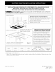
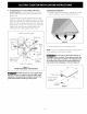
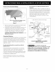
Cooktop Dimensions
30" Min. *
(76.2 cm)
IMPORTANT INSTALLATION INFORMATION
• All electric cooktops run off a single phase, three-wire
or four-wire cable, 240/208 volt, 60 hertz, AC only
electrical supply with ground.
• Minimum distance between cooktop and overhead
cabinetry is 30" (76.2 cm).
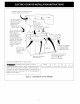
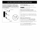
Cooktop Cutout Dimensions
C
4" X 8" (10.2 cm x 20.3 cm)
! to route armored
cable if a panel is present
* 30" (76.2 cm) min. for unprotected cabinet
24" (61 cm) min. for protected surface
Figure 1
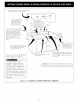
IMPORTANT INFORMATION FORPROPER
INFRAREDTOUCH CONTROL FUNCTION
In order to prevent faulty adjustment of the
controller sensors due to foreign light, the
intensity of illumination at the first power on
should not exceed 1000 lux. Direct irradiation
of the touch panel with light from a spotlight
should be avoided during the power process.
If the illumination exceeds 1000 lux, the
control doesn't display the version and stop
the automatic adjustment. In this caseturn
down the controls switch of the light till the
illumination is lower than 1000 lux.
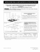
E DEPTHBELOW
C00KTOP*
s(12.7)
All dimensions are in inches (cm).
* Allow 2" (5 cm) space below cooktop to clear the electric cable and allow for installation of the junction box on the
wall at the back of the cooktop.
Printed in the United States P/N 318201446 (0706) Rev. A
English - pages 1-6
Espaf_ol- pages 7-12