
Installation Guide


INSTALLATION OVERVIEW
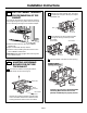
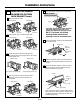
C1. Attach Mounting Plate to Wall
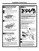
C2. Prepare Top Cabinet
C4.
C5.
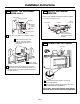
Mount the Microwave Oven
IMPORTANT NOTES:
• Make sure the screws for the blower motor and blower
plate are securely tightened when they are reinstalled.
This will help to prevent excessive vibration.
• Make sure the motor wiring has been properly routed
and secured, and that the wires are not pinched.
Installation Instructions
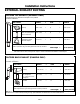
RECIRCULATING (Non-Vented Ductless)
C
Install or change Charcoal Filter
C3. Check Blower Plate
Place the mounting plate against the wall and
insert the toggle wings into the holes in the wall
to mount the plate.
NOTE: Before tightening toggle bolts and wood
screw, make sure the bottom of the mounting plate
touch the bottom of the cabinet when pushed flush
against the wall and that the plate is properly
centered under the cabinet.
CAUTION: Be careful to avoid pinching fingers
between the back of the mounting plate and the wall.
Tighten all bolts. Pull the plate away from the wall
to help tighten the bolts.
4
3
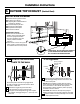
ATTACH THE MOUNTING
PLATE TO THE WALL
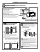
C1.
Attach the plate to the wall using toggle bolts.
At least one wood screw must be used to attach
the plate to a wall stud.
Remove the toggle wings from the bolts.
Insert the bolts into the mounting plate through
the holes designated to go into drywall and
reattach the toggle wings to
3
⁄4″ (19 mm) onto
each bolt.
1
Wall
Mounting
Plate
Spacing for Toggles
More Than Wall
Thickness
Bolt End
Toggle
Bolt
Toggle Wings
To use toggle bolts:
2
NOTE:
Cabinet
Cabinet
If the cabinet depth including the cabinet doors
is more than 13""'' then the unit must be spaced
out from wall using adequate materials supporting
150 Ibs to allow proper top vent air exhaust.
EN-20
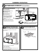
IMPORTANT :Do not remove the cardboard
spacers between the heat shield and door.
3
/
8"
TO
EDG
E
NOTE
:
IT
IS
VE
RY
I
MPO
R
TANT TO
READ
AND FO
LLO
W
T
HE
D
IRECTION
S
IN THE INSTALLA
T
ION INSTR
U
CTIO
N
S
BE
F
O
RE PR
O
CEED
ING
WITH
T
H
I
S
REAR W
A
LL TEM
PLA
T
E
.
T
h
i
s
R
e
a
r
Wa
ll
Te
m
pl
ate
se
r
v
e
s
to p
o
s
it
io
n
th
e
b
o
tto
m
m
ountin
g
p
l
a
te
a
nd
to loc
a
t
e th
e ho
r
i
z
on
t
a
l
e
x
h
au
s
t
ou
t
le
t
.
1
. Us
e a
l
e
v
el
to
c
h
ec
k
th
at the
t
e
m
p
l
a
te
i
s
p
o
s
it
ione
d
a
c
c
u
r
a
tel
y
.
2. L
o
c
ate
a
nd
m
a
r
k
a
t lea
s
t o
ne
s
tu
d
on th
e
l
e
ft o
r
r
igh
t
s
id
e
o
f th
e c
e
nte
r
l
i
n
e
.
It
i
s imp
o
rta
n
t to u
s
e
a
t le
as
t
one wo
od
s
c
re
w
m
o
unted
f
i
r
mly
i
n
a
s
tud
to supp
or
t the
w
e
ig
ht
of
the m
ic
r
o
w
a
v
e.
M
a
r
k
t
w
o
a
d
di
ti
on
a
l,
ev
e
n
ly
s
pa
c
ed
l
o
c
a
ti
o
n
s
f
o
r
the
s
upp
l
ied
to
g
gle bol
t
s.
3. D
r
i
ll
h
ol
e
s
in
th
e
m
ar
k
ed l
o
c
atio
n
s
.
Wh
er
e t
h
er
e is
a
stu
d
,
dr
il
l
a 3/1
6"
h
ol
e
fo
r
woo
d sc
r
e
ws
.
F
o
r
h
o
les
t
h
at
do
n
o
t lin
e up
w
it
h
a
s
tu
d,
d
r
il
l 5
/8
"
h
o
le
s
fo
r
to
gg
l
e bo
lts
.
DO
NOT
I
N
S
T
AL
L
T
HE
MO
U
NTI
N
G
P
L
ATE
AT
T
HIS
T
I
ME.
4. R
e
m
o
v
e
th
e te
mpla
t
e
fro
m
the r
ea
r
wal
l
.
5
.
Re
v
i
e
w
t
h
e
In
s
ta
ll
a
t
i
on
Instr
u
c
tio
n bo
ok
for
y
ou
r
i
n
s
ta
l
l
ati
o
n si
tua
t
i
on
.
Locat
e and m
ar
k
holes
to ali
gn with holes
in t
he
mounting
p
l
ate.
IMP
O
RTANT
:
LO
CA
T
E
AT LEA
ST
O
NE STUD
O
N E
I
T
HER
S
I
D
E
O
F
TH
E
CENT
E
RLI
N
E
.
MARK
T
HE LO
CA
TION
F
O
R 2 ADDIT
I
O
N
A
L, EV
ENL
Y
SP
ACE
D T
O
GGLE
BO
LTS
IN T
HE MOUN
TING
PLATE
A
R
E
A
.
Locate
and mar
k
h
oles
to a
l
i
g
n with holes
in t
he
mou
nting
plate.
IMP
ORTANT
:
LO
C
A
T
E
AT LEA
ST O
N
E
STUD
O
N EI
THER SI
D
E
O
F
TH
E
CENT
E
R
LI
N
E
.
MARK
T
HE LOCATIO
N
F
O
R 2 ADDITION
A
L
, EV
ENL
Y
SP
ACED
TOG
GLE BO
L
TS IN
THE MO
UN
TING
P
LATE
AREA
.
Trim the r
e
ar
wal
l tem
pl
at
e along
the do
tt
ed
line.
Trim the rear
wal
l t
em
pl
a
t
e along
t
he
do
tted lin
e.
12"
4"
Da
r
l
e
v
u
e
lt
a
a
la
ho
ja
p
a
r
a
c
o
ns
u
l
t
a
r
la
v
e
r
s
i
ó
n
e
n
E
s
pa
ño
l.
Do not remove the metal heat shield.