KESMAC Transportable Reel Mowers 3, 5, 7, 9 and 11 Gang Mowers Fairway Mowers Vertical Mowers Operators Manual Manual Part No. KM99026. Rev. 05/07 KESMAC Inc. 23324 Woodbine Avenue, Keswick Ontario Canada L4P 3E9 Tel (905) 476-6222 Fax (905)-6744 Web Site www.Kesmac.com info@kesmac.
KESMAC Transportable Reel Mowers FOREWORD The Operator’s Manual must be kept on the machine at all times. The Manual is provided to give the Owner/Operator the correct information on the safe operating procedures, minor repairs and the maintenance of the machine. Important features and specifications are included to help you operate your Kesmac mower safely and efficiently.
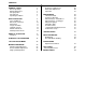
CONTENTS SAFETY PRECAUTIONS GENERAL SAFETY Before Operating During Maintenance Safety Symbols Safety Decals Operating Conditions 1 2 2 3 3 4 7 DAILY INSPECTION Tires and Wheels Drive Belts & Sheaves PTO Shafts Tongue and Hitch Hydraulic System Guards and Decals Initial Operation Check 8 8 10 11 11 12 12 12 HOOK-UP TO TRACTOR Transport 13 14 HYDRAULIC LIFT OPERATION 16 LIFT CAIN ADJUSTMENT 20 MOWING PROCEDURE Cutting Height Adjustment Reel to Bedknife Adjustment Single point Adjustment 22 23 24 25
SAFETY PRECAUTIONS The correct operating procedures, and strict adherence to recommended service schedules, are important in contributing to the safe operation of the machine and the safety of the operator and others. It is important when carrying out service or repair work on Kesmac Mowers to follow all of the operating and service safety procedures that are outlined in this manual, to ensure your own safety and that of any bystanders.
SAFETY PRECAUTIONS – General Safety The Operator’s Manual brings to your attention situations that can arise during the safe and routine operation of your Kesmac Mower. It also informs you how to deal with non-routine conditions and situations, and avoid possible injury to yourself or to others. The manual outlines the safe practices that must be followed when operating the mower when it is equipped with standard equipment.
SAFETY PRECAUTIONS During Maintenance • Use only genuine Kesmac parts. Parts that are not supplied by Kesmac may not meet Kesmac Engineering specifications or standards of manufacture. • The use of parts not approved by Kesmac may result in component failure possibly resulting in an accident and injury to the operator or bystanders. • Relieve pressure in hydraulic systems before attempting to carry out any service work. Failure to observe this precaution may result in serious personal injury.
DECALS. See Pages 5 & 6 also.
GENERAL SAFETY Operating Conditions Commercial mowers are subjected to a variety of ground conditions. Mowing machine operators must understand the need to pay constant attention to the changing conditions that they may encounter while operating the machine. These precautionary measures will help in more efficient operation and reduced equipment ‘down time’. IMPORTANT Positive drive PTO Mowers have a powerful cutting action, very little will ‘stop’ them.
DAILY INSPECTION To enable customers to implement service procedures, and design changes that are recommended to improve the operation and service life of the mower, Service Bulletins are issued by the factory. It is important that Service Bulletin instructions are implemented as soon as possible. IMPORTANT At the end of the workday clean the mower thoroughly.
DAILY INSPECTION Cont.. OUTRIGGER WHEELS Fig.1 Serial No. Up to 73. Dual Wheels. It is important that the Roller Bearings and Hub Cavity are kept packed with grease. Apply grease daily. IMPORTANT Also check that the Lock Collars at both ends of the Axle are locked to the Axle by the Set Screws Fig.1 Fig.2 Serial No. 74 onwards. Single Wheel. Mowers with the Taper Roller Bearings, (Cup and Cone), do not require daily maintenance. Refer to pages 33, 34 and 35 for service procedure. 9 Fig.
DAILY INSPECTION DRIVE BELTS AND SHEAVES Fig.3 Check all Drive Belts for signs of cracking, excessive wear, cuts, or stretching. Sheaves must be kept free of debris. Worn Sheaves allow a belt, that has no excessive wear, to ‘bottom out’ in the ‘vee’ groove. A shiny, polished track in the bottom of the ‘vee’ groove is evidence of a badly worn drive belt and/or Sheave. Fig.3 PRIMARY BELTS Fig.4 The Primary Drive Belts are tensioned by spring tensioned ‘idlers’.
DAILY INSPECTION PTO SHAFT Fig.6 The PTO Shaft must be installed, relative to the tractor, as shown. WARNING Do not operate the machine without the PTO Shaft Shields in place. To do so could result in serious personal injury. Fig.6 The PTO Manufacturers Service Manual is supplied with the machine. It is important that inspection, service and maintenance instructions for the PTO are followed. Grease the PTO daily. TONGUE TUBE Fig.7 Check the nuts and bolts ‘A’ for tightness.
DAILY INSPECTION HYDRAULIC SYSTEM • • • Check all hydraulic fittings, connections and hoses for signs of leaks, damage or wear. Hoses must be routed clear of any moving parts, and secured to prevent ‘rubbing’ to prevent damage. Keep all hydraulic connections clean. Refer to pages 16 to 19 for the hydraulic system diagrams and operation. GUARDS AND DECALS Before starting mowing operations : • Check that all safety Guards are in place and not damaged.
HOOK-UP TO TRACTOR Fig.8 It is important that the Mower Frame is ‘level’ for the correct set-up for mowing. Connect the Mower Swivel Hitch to the Tractor Draw Bar using an approved Draw Pin. The front and rear Jack Shafts should be the same height from the ground. IMPORTANT Adjust the Swivel Hitch to set the Mower Frame level to the ground. It is removable to allow it to be rotated 180 degrees to increase the adjustment relative to the Tractor Draw Bar. (Optional Ball Hitch also illustrated).
HOOK-UP TO TRACTOR Connect the Mower ‘Quick Connects’ to the tractor accessory hydraulic connections. Keep the hydraulic connections clean. TRANSPORT WARNING Relieve any hydraulic pressure in the mower hydraulic system before connecting the mower to the tractor hydraulic system. Failure to do so could result in serious personal injury . Fig.9 To relieve pressure in the Mower Hydraulic System press the plunger ‘A’ in the Disconnect, ‘inwards.
TRANSPORT LOWERING THE REELS LIFTING THE REELS Before ‘lowering ‘ the Reels, position the Mower on level ground. If on a slope face the mower ‘up hill’, this allows the reels to lower evenly on both sides, and prevents damage to the Reel Drives. Check that the transport Safety Chains are un-hooked from the Reels and are in their ‘stowed’ position. IMPORTANT To prevent damage to the Reels do not lower them with the Safety Chains in their transport positions. Do not set the tractor engine RPM too high.
HYDRAULIC LIFT OPERATION REEL/WING - LIFT SEQUENCE Fig.10. From Serial No. 232. (See Fig.11 for earlier machines) Hydraulic oil pressure to the ‘raise’ circuit lifts the five main reels first, followed by the wing reels and lastly the wing frames. The cylinders are ‘locked up’ by Pilot Check Valves. The Pilot Check Valves are released by pressure on the ‘lower’ side of the hydraulic circuit. REEL/WING - LOWER SEQUENCE Fig.
HYDRAULIC LIFT OPERATION REEL/WING - LIFT SEQUENCE Fig.11 Machines up to Serial No. 231. Hydraulic oil pressure to the ‘RAISE’ circuit lifts the five main reels first, followed by the wing reels and lastly the wing frames. The cylinders are ‘locked up’ by Pilot Check Valves. The Pilot Check Valves are released by pressure on the ‘LOWER side of the hydraulic circuit. REEL/WING - LOWER SEQUENCE Fig.
HYDRAULIC LIFT OPERATION SEQUENCE VALVE SETTING. (7, 9 & 11 Gang only) Fig.12 If the main (center five) reel assemblies start to lower before the wing frames/reels have finished their cycle, the Sequence Valve requires re-setting, as follows : • • • • • • 7 – 9 – 11 GANG ONLY Back-off the Jam-nut. With a 3/16 Allen Key turn the Sequence Valve Adjuster one half turn ‘INWARD’. Raise the reel assemblies. Start ‘lowering’ the reels until they are fully down. The main reels should not move.
HYDRAULIC LIFT OPERATION SEQUENCE VALVE MANIFOLD, RELIEF VALVE SETTING To prevent damage to the lift linkage if there is a ‘hangup’ of a Lift Chain, a Relief Valve is installed in the Manifold Block to control oil pressure to the Lift Cylinders. The Relief Valve setting prevents excessive oil pressure at the Lift Cylinders at engine ‘idle speed’. Higher ‘idle speeds’ will not increase the ‘lift rate’, this is controlled by Restrictor Orifices in each cylinder.
LIFT CHAIN ADJUSTMENTS Fig.14 The Lift Chains for the rear outer reels, No’s 4,5,8,9,10 & 11,are fitted with chain adjusters that ensure that the ‘Snubber’ Rollers engage correctly in the catchers. Refer to page 21 for the correct sequence of reel numbering and the Lift Chain locations. REELS 4 AND 5 Fig.15 Before adjusting the Lift Chains on reels No’s 4 and 5, check that the main lift arms work in unison.
LIFT CHAINS ADJUSTMENT REELS 4 AND 5 Cont. Fig.15. (page 20) Extend the cylinder and check that the chain bolt heads are level. Extending the Cylinder Rod End Clevis rotates the RH Arm C.C.W. and the LH Arm C.W. Retracting the Rod End Clevis rotates the arms in the opposite direction. Fig.14 and 16. With Reels 4 and 5 ‘raised’, check that the ‘Snubber’ Rollers are located in the main frame ‘catchers’. Shortening the lower inner chain, No.5, will lift the Reel. Shortening the upper outer chain, No.
MOWING PROCEDURE CUTTING HEIGHT ADJUSMENT Preferably position the Mower on level ground, if on a slope, face ‘up hill’ to allow the reels to lower evenly and prevent possible damage to the reel drives. Fig.17 For initial set-up of the mowing height : • Position the mower on level ground and lower the reel assemblies. Place a 1 in. thick spacer under the bed-knife. • Back-off the height adjuster lock-nuts, turn each Adjuster until the roller is touching the ground. • Tighten the height adjuster lock-nuts.
CUTTING HEIGHT ADJUSTMENT FAIRWAY. FLOATING HEAD Fig.18 A special tool is available that ensures that each mowing unit cuts at the same height, and also that the Reels and Bed-knives are parallel to each other. To set the cutting height : • Raise the Reels to transport position. Set the front and rear rollers to ‘minimum height’ by releasing the lock-nuts and turning the front and rear Height Adjusters ‘clockwise’. • Set the required ‘height of cut’ ‘A’ with the front Adjusting Screw in the Adjusting Bar.
REEL TO BED KNIFE ADJUSTMENT Pre-single point adjustment units. Fig.19 When the reels are sharp, and correctly adjusted to the bed-knife, they will cut paper as clean as scissors. To adjust the reel blade to bed-knife clearance : • Check the Bed-knife and the Bed-knife Holder Screws for tightness. • Compress the Telescopic Arm with the belt release tool, to allow the Reel to be rotated. CAUTION The Telescopic Arm is heavily ‘spring loaded’. Exercise care when compressing it to avoid personal injury. Fig.
REEL TO BED-KNIFE SINGLE POINT ADJUSTMENT Adjust the Reel to Bed-knife ‘contact’ to give an even cut across the full length of the Bed-knife, as shown in Fig.20. Fig.21 As wear takes place on the Reel Blades and the BedKnife, the ‘single point adjuster’ provides a quick, easy, and accurate method to make adjustments. Spiral Reel Blades pass over the bed-knife in a scissor action, the blades just brushing the bed-knife.
VERTICAL MOWER. DEPTH OF CUT ADJUSTMENT Depth of cut changes as the height adjuster wheel pivot, relative to the frame. Notches on the wheel height adjuster allow ‘indexing’, ensuring the height adjustment is equal at both ends of the Reel. Fig.22 To adjust the depth of cut : Note the position of the notches on the height adjusters, they must be the same at both sides of the reel. • Back-off both locknuts. • Turn the height adjusters CW to increase, CCW to decrease, the depth of cut.
VERTICAL MOWER – OPERATION CAUTION It is important that the operating instructions are followed to avoid serious damage to both the machine and also to the turf. • • • Recommended operating procedure : • • • • • • Position the machine on level ground. Lower the cutting reels until they are just clear of the turf. Engage the tractor PTO at low rpm to avoid shock loads to the mower drive train. Slowly lower the cutting reels into the turf. Select the appropriate tractor gear range, to give 3 to 5 mph, (4.
ROUTINE MAINTENANCE In addition to the daily maintenance on pages 8 to12, the following maintenance schedules are recommended. IMPORTANT These schedules are based on operating in ‘average’ conditions. In wet, heavy or sandy conditions, more frequent periods of service are recommended. In such conditions the Roller Bearings should be greased every 20 hours. 40 HOURS or WEEKLY Refer to Fig.24 Apply grease to : • Reel Bearings. • Roller Bearings. (See note above). • Telescopic Arm. • Jackshaft Bearings.
ANNUAL MAINTENANCE INSPECTION IMPORTANT To maintain the efficient and reliable operation of your Kesmac Mower it is important that the checks and maintenance in the following schedule are carried out. It is recommended that this be done at the end of the mowing season, before storage, and also before the start of a new season. Carry out all of the previously recommended service and maintenance schedules. Also check the following : • • • • • • • 29 Jackshaft Couplings.
LUBRICATION Gearbox. See pages 31 and 32 Jackshaft Bearings Do not over grease. Standard Mower Fairway Mower Dual Wheel Single Wheel Verticut Typical – 16 Locations Telescopic Arm Fig.24 Idler Wheel – Two Locations A = Grease.
GEARBOX LUBRICATION Fig.25 Check the Gearbox oil level every 80 hours of operation. The oil level dipstick/breather is located on the top of the Gearbox. Top-up as necessary with a recommended oil : PREFERRED • AMOCO PERMAGEAR EP220 OPTIONS • • TEXACO MEROPA PETROCAN ULTIMA EP220 After the initial operating period of 500 hours, or 6 months, the oil should be drained, while it is warm, and the Gearbox refilled with new oil.
GEARBOX LUBRICATION Fig.26 The Gearbox illustrated in Figure 26 was fitted on Kesmac Mowers up to Serial number 365. To check the oil level : Remove the Vented Filler Plug and also the Level Plug. Oil should ‘just flow’ from the Level Plug. Top-up as necessary with recommended oil. • Refer to page 31 for recommended oils. • Follow the recommended oil change frequency as shown on page 31. Fig.26 NOTE The Gearbox illustrated above was fitted on Kesmac Mowers up to Serial Number 365.
MAINTENANCE Main Wheel Axle Assembly . (From Feb.07.) The Axle Assemblies should be checked every 12 months. To remove a Wheel/Axle assembly : Fig.27 • Lower all Reels to the ground. Remove Reels 4 and 5. • Jack-up and support the Mower Frame. Remove the Bearing Blocks,(see Fig.28), and Wheel/Axle Assembly. • Remove Wheel from Hub. • Locate and back-off the Setscrew in the Outer Axle. • Unscrew the Outer Axle from the Stub Axle. • Remove the Hub c/w Seals and Bearings from the Axle.
MAINTENANCE Main Wheel Axle Assembly. Serial No’s 357 to February 2007. Taper Roller Axles should be checked every 12 months. To remove a Wheel/Axle Assembly : Fig.28 • Lower Reels to the ground. Remove Reels 4 and 5. • Jack-up and support the Mower frame. Remove the Bearing Blocks and the Wheel/Axle Assembly. • Remove the Wheel from the Axle Hub. • Remove Retainer Bolt, and End Cap from the Axle. • Release the two Setscrews and remove the Axle Nut and Spacer. • Pull the Hub off the Axle.
MAINTENANCE Outrigger Single Wheel. (From Serial No. 73.) Fig.29 Taper Roller Axles should be checked every 12 months. To remove the Wheel Axle Assembly : Fig.29 Raise the wheel, put a Jack under the frame on 7-Gang, and under a Tie-rod mount on 9 and 11 Gang Mowers. • Remove the Wheel. • Remove Dust Cap, Cotter Pin, and Adjusting Nut. • Pull the Hub, Bearings and Seal off the Axle. • Clean and inspect the Bearings. If there are signs of wear or damage, replace the Cups and Cones as assemblies.
MAINTENANCE Wing Kick Springs. After several seasons of operation the Wing Kick Springs may loose some of their tension. Washers can be added under the Springs to make up for the loss of tension. Add three washers maximum, if this is not sufficient, fit a new Kick Spring. WING KICK SPRINGS To add Washers : Fig.31 • Lower the Wings. • Remove the Cotter Pin from the Rod End. • Drive the Rod, Rod Guide, and Spring from the Spring Barrel.
MAINTENANCE Main Drive Belts To replace the front and/or rear Main Drive Belts : Fig.32 • Remove the Drive Belt Covers. • Remove the Idler Tension Eye Bolts and Springs. • Remove the Jackshaft Couplers. • Remove the Drive Belts from the Gearbox and the Drive Shaft Sheaves. IMPORTANT Drive Belts must be replaced in pairs. • • • • Insert the new Drive Belts through the space between the Jackshafts and onto the Drive Shaft Sheave. Re-fit the Jackshaft Couplers Fit the Drive Belts onto the Gearbox Sheave.
MAINTENANCE Reel Drive Belts. When fitting Belts to Reels 2 or 3, the Main Drive Belts and the Jackshaft Couplers, must be removed first. See page 37. To keep the Compression Tool clear of the Stay Rod the Binder Collar and Chain may be used. CAUTION When the Binder Collar is used check it is firmly in place on the ¾ nut, before compressing the Telescopic Arm. To replace the Reel Drive Belts. Reels 1, 4 and 5. : Fig.33 • Remove the Safety Chain at the Stay Rod. Attach the Release Tool.
MAINTENANCE Reel Drive Belts To replace the Reel Drive Belts. Reels 2 and 3. Fig.34 • Remove the Safety Chain from the Stay Rod and compress the Telescopic Arm with the Compression Tool as shown in Fig.33. • Remove the Front Jackshaft Couplers and pull the belt through the gap between the Jackshafts. Install the new belt onto the sheaves. Fit the Jackshaft Coupler. • Carefully release the Compression Tool and reattach the Safety Chain. Fig.34 To replace the Reel Drive Belts. Reels 6 and 7. Fig.
MAINTENANCE Reel Drive Belts To replace The Reel Drive Belts. Reels 8 and 9. • • • • • • • Remove the Sheave Guard. Remove the Safety Chain at the Stay Rod. Compress the Telescopic Arm. Refer to Fig.33 Remove the Belt from the Sheaves. Release the Compression Tool to fully expand the Telescopic Arm. Pull the Reel ‘out,’ to separate the Telescopic Arm, and remove the Belt. Install a new Drive Belt and re-assemble in the reverse order. To replace the Reel Drive Belts. Reels 10 and 11. • • • • Fig.
MAINTENANCE Main Jackshaft Bearing replacement. IMPORTANT The Bearing Shims must be replaced exactly as removed, if the Jackshaft Bearings are removed. Fig.38 If the Jackshaft Bearings are replaced, the Jackshafts alignment must be checked and re-set. The shafts are aligned, fore and aft, with Shims behind the bearings, and vertically with slotted holes in the bearing flanges. • Assemble the Shafts, Sheaves and Bearings with Lock Collars, and Shims in place as removed.
SPECIFICATIONS 11-Gang Standard 9-Gang 7-Gang 5-Gang 11-Gang Fairway 9-Gang 7-Gang 5-Gang Verticut 5-Gang 25.ft. 20ft.’ 6in. 16ft. 11ft. 6in. 25ft. 20ft.’ 6in. 16ft. 11ft. 6in. 11ft. 3in. 7620.mm ½ to 3 ¼.in. 6248 4877 3505 7620 6248 4877 3505 3429 0 to 1 in. Width of Cut Height of Cut Same Same Same Same Same Same Same 13 to 83.mm 3778.lbs 3120 2860 1847 4710 3345 3035 1972 1714.kg 106.in 1415 80 1297 79 838 50 2137 82 1518 1377 79 895 58 2692.
SPECIFICATIONS STEP-UP DRIVE RATIO PTO. 1 3/8 inch diameter, with six splines. Wide Angle PTO Shaft. Standard –1.64 : 1 Optional – 2.20 : 1 NUMBER OF REELS 5, 6, 7 or 9 NORMAL OPERATION PTO Speed, Standard 540 rpm. TRACTOR POWER. Nominal. Note : Horsepower varies to type of turf and mowing conditions. 11-Gang – 45 hp. 9-Gang – 42 hp. 7-Gang – 28 hp. 5-Gang – 20 hp.
BACKLAPPING ATTACHMENT Hydraulic Operation. WARNING During the Backlapping operation the Reels will be rotating, while the Mower is stationary. Keep all bystanders away from the machine to avoid possible personal injury The Backlapping Unit reverses the rotation of the Reels and reduces the rotation speed. Grinding compound is applied to the Reel Blades while they rotate, to give a sharp cutting edge. Fig.40 IMPORTANT Before starting ‘backlapping’, adjust each Reel ‘parallel to its Bedknife’.
BACKLAPPING OPERATION NOTE The Applicator Brush must be free of grease or oil. • • • • Apply Grinding Compound to the Reels and allow two minutes for it to ‘work in’. Spray a fine ‘mist’ of water onto the Reels and allow a further two minutes for it to ‘work in’. Apply a second application of Compound, followed by water ‘mist’. Continue this process until the Reels and Bedknife are sharpened satisfactorily.
REEL AND BEDKNIFE SHARPENING Fig.42 When grinding and sharpening the Reels and Bedknives the angles and dimensions shown must be adhered to. After grinding and sharpening, Backlap the Reel Units as recommended on pages 44 and 45. Fig.
WING FRAME Optional Castor Wheel. 11 Gang only. The Optional Castor Wheel is fitted to the outer Wing Frames to improve cutting performance when mowing on undulating ground. Fig.44 The Spindle Support Bracket is bolted to the top of the modified frame tube, and behind the Jackshaft Bearings. • • • Apply grease to the Spindle and the Wheel Hub - every week. Refer to the Tire Sidewall for recommended operating pressure. Inspect the tire daily for excessive wear, bulges or damage.
LIFT CHAINS - ATTACHMENT POINTS Fig.
TORQUE GUIDE Grade 5 and 8 Fasteners. (Coarse Thread). Grade 5 49 Grade 8 SIZE PLATED PLAIN PLATED PLAIN ¼ - 20 76 in.lbs 8 ft.lbs. 9 ft.lbs. 12 ft.lbs. 5/16 -18 13 ft.lbs.