Owner's Manual and instal lation instructions ® 29-inch Wide ELECTRIC DRYERS B m rm. m rl IMPORTANT: Your dryer may took different from the dryer shown. Read and follow all safety and operating instructions before first use of this product. Sears, Roebuck PART NO 3405586 and Co., Rev A Hoffrnan PRINTED Estates, IN U.SA IL 60179 U.S.A.
BEFORE SEARS USING ELECTRIC IMPORTANT OPERATING LAUNDRY NEW DRYER DRYER SAFETY INSTALLATION CARING YOUR 2 WARRANTY 3 iNSTRUCTIONS 4 INSTRUCTIONS YOUR 5 DRYER 29 TiPS FORYOUR 36 DRYER 38 TROUBLESHOOTING SEARS MAINTENANCE 41 AGREEMENT 43 Please read this manual. It will help you install and operate your new Kenmore Dryer in the safest and most economical way.
Full One Year Warranty on Mechanical and Electrical Parts For one year from the date of purchase, Warranty Restriction If the dryer is subjected to other than private family use, all warranty coverage if this dryer is effective for only 90 days. Warranty Service is installed and operated according to the instructions in this manual, Sears will repair or replace any of its mechanical or electrical parts if they are defective in material or workmanship.
YOUR SAFETY iS IMPORTANT TO US. WARNING: To reduce the risk of fire, electric shock, or injury to persons when using your dryer, follow basic precautions, including the following: • Read all instructions before using the dryer. • Do not dry articles that have been previously cleaned in, washed in, soaked in, or spotted with gasoline, dry-cleaning solvents, or other flammable or explosive substances as they give off vapors that could ignite or explode. • Do not allow children to play on or in the dryer.
INSTALLATION OVERVIEW For a complete list of tools and parts needed, see pages 5-7. A. SELECT LOCATION Standard FOR YOUR Installation (pgs. DRYER 8-9) (pgs. 8-10) Recessed Installation Area/C!oset Instructions (pgs. i B. INSTALL LEVELING LEGS (p. 11) \ \ Tools S! Adjustable wrench Needed: Parts Needed: (supplied with dryer) Level 4 leveling legs Two corner posts (from dryer carton) Flashlight (optional depending on installation) 9-10)
C.MAKE ELECTRICAL CONNECTION (pgs. 12-22) @ If using a power Tools _/4-inch nut driver (shown) or socket wrench cord: Needed: Parts Needed: #2 Phillips head screwdriver New 3- or 4-wire, 30-amp., U.L.
D.CONNECT EXHAUST Tools Tin snips (pgs.
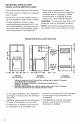
A. SELECT LOCATION FOR YOUR DRYER Selecting the proper location for your dryer makes installation easy and gives you the best drying performance. STANDARD INSTALLATION Check location where dryer will be installed. Proper installation is your responsibility. Make sure you have everything necessary for correct installation (see illustration below). The dryer must can be exposed not be installed where it to water and/or weather.
DRYERDIMENSIONS Mostinstallations willrequire atleast 5-inchclearance behind thedryerfor thedryervent. Location mustbelargeenough tofully opendryerdoor.
RECESSED AREA/CLOSET iNSTALLATiON iNSTRUCTiONS Check governing codes and ordinances. This dryer may be installed area or closet. in a recessed The dryer must not be installed where it can be exposed to water and/or weather. * Proper operation of dryer cycles requires temperatures above 45°F (at lower temperatures, the dryer may not shut off at the end of automatic cycles and drying times will be extended). MINIMUM * Check code requirements.
B. iNSTALL LEVELING LEGS Leveling your dryer correctly will reduce operating noise and provide improved drying performance. STEP 5. Stand the dryer up and move it close to its final location. Leave enough room to connect the exhaust vent. STEP 6. Check levelness of dryer by placing a level on top of the dryer, first side-to-side; then front-to-back. STEP 1. Take two of the cardboard corners from the carton. Place them on the floor in back of the dryer. STEP 2.
C,MAKE ELECTRICAL ELECTRICAL CONNECTION It is your responsibility: • To contact a qualified • To assure that the electrical electrical installer. installation is adequate and in conformance with the National Electrical Code, ANSI/ NFPA 70 - latest edition and all local codes and ordinances.
i. THREE-WIRE CONNECTION ELECTRICAL TO RECEPTACLE Use a 3-wire power supply Local codes may permit the use of a U.L.-listed, 120/240-volt minimum, 30-ampere, dryer power supply cord kit (pigtail). Power supply cord should be type SRD or SRDT and be at least four feet long. The wires that connect to the dryer must end with ring terminals or spade terminals with upturned ends. cord: Do not use an extension cord with this dryer.
GROUNDING INSTRUCTIONS Thisappliance mustbegrounded. Intheevent of malfunction or breakdown, grounding will reduce the risk of electric shock by providing a path of least resistance for electric current. The power supply cord must be plugged into an appropriate outlet that is properly installed and grounded in accordance with all local codes and ordinances. WARNING: improper connection equipment-grounding conductor result in a risk of electric shock.
II. THREE-WIRE CONNECTION ELECTRICAL (DIRECT WIRE) Prepare cable as directed: A conduit connector GROUNDING Fire Hazard Use 10 gauge solid copper wire. Use a UL approved strain relief. Disconnect power before making electrical connections. Connect neutral wire (white or center wire) to center terminal (silver). Ground wire (green or bare wire) must be connected to green ground connector. must be installed at junction box.
STEP2.Remove hold-down screwand STEP 4a. Place the hook-shaped terminal blockcover. of the wire over the terminal block The open side of the hook should H01d-d0wn screwto the right. Squeeze hook end of together STEP 3. Attach a 3/4-inch, U.L.-listed relief to the hole below terminal block opening. Strain relief should have a tight fit with dryer cabinet and be in a horizontal position. Put the direct wire cable through the strain STEP 4. Loosen relief. or remove terminal block screws.
ALTERNATE CONNECTION: If localcodesdonotpermitthe connection ofa frame-grounding conductortotheneutralwire: STEP1.Disconnect power. STEP2.Makesurethepowersupply cordordirectwire cable is in place (see STEPS 1-3 on page 14 for power cord connections or STEPS 1-3 on pages 15-16 for direct wire connection). STEP 3. Remove the neutral grounding wire (green/yellow wire) from external grounding connector screw. Loosen or remove terminal block screws.
Ill. MAKE FOUR-WIRE ELECTRICAL CONNECTION TO RECEPTACLE Use a 4-wire power supply Local codes may permit the use of a U.L.-listed, 120/240-volt minimum, 30-ampere, dryer power supply cord kit (pigtail). Power supply cord should be type SRD or SRDT and be at least four feet long. The wires that connect to the dryer must end with ring terminals or spade terminals with upturned ends. cord: For mobile Fire Hazard Use a new UL approved 30 ampere power supply cord.
GROUNDING INSTRUCTIONS This appliance must be grounded. In the event of malfunction or breakdown, grounding will reduce the risk of electric shock by providing a path of least resistance for electric current. The power supply cord must be plugged into an appropriate outlet that is properly installed and grounded in accordance with all local codes and ordinances. WARNING: Improper connection equipment-grounding conductor result in a risk of electric shock.
STEP5.Connect neutralgrounding wire andtheneutralwire(whiteorcenter) ofpowersupplycordunderthecenter screwofterminal block. STEP6.Connect theothertwoinsulated wirestoouterterminal blockscrews. STEP7.Connect thegrounding wire (green) ofthepowersupplycordtothe external grounding conductor screw. Securely tighten allelectrical connections. STEP8.Inserttabofterminal block coverintoslotofthedryerrearpanel. Secure coverwithhold-down screw.
IV. FOUR-WIRE ELECTRICAL CONNECTION (DIRECT WIRE) Prepare cable GROUNDING INSTRUCTIONS This appliance must be connected to a grounded metal, permanent wiring system; or an equipment-grounding conductor must be run with the circuit conductors and connected to the as directed: Fire Hazard equipment-grounding lead on the appliance. terminal STEP 1. Disconnect power. STEP la. Strip 5 inches or of outer covering from end of cable. Leave bare grounding wire at 5 inches.
STEP 3. Attach a 3/4-inch, U.L.-listed strain relief to the hole below terminal STEP 6. Place the hook-shaped the wire over the terminal block block opening. Strain relief should have a tight fit with dryer cabinet and be in a horizontal position. Put the direct wire cable through the strain relief. The open side of the hook should face to the right. Squeeze hook end of wire together to form a loop. STEP 4. Remove the center block screw. Remove ing wire (green/yellow grounding screw. end of screw.
D. CONNECTEXHAUST • If using an existing exhaust system, disconnect vent from the dryer and clean one section at a time until you reach the exhaust hood. To clean out A properly exhausted dryer will give you the shortest drying time, lower your utility bills, and extend the life of the dryer. lint, you can use the hose attachment on your vacuum, or use a pole or wire with a feather duster or rag attached. Fire Hazard Use a heavy metal vent. Do not use a plastic Do not use a metal vent. foil vent.
ROUTE THE VENT Typical installations rear of the dryer. DETERMINE exhaust from the Avoid pushing the dryer tightly against a wall. This can crush or kink the vent. Use the straightest path you can, where possible. Avoid 90 ° turns. Maximum VENT Exhaust offset connections for standard - (see pgs. 25-26) NOTE: If a combination of rigid metal vent and flexible metal vent is used, use instructions for flexible metal vent.
STANDARD OFFSET CONNECTIONS STEP 3. Place a clamp on each vent elbow and connect elbow Using4-inchrigidheavymetalvent: ofdryer's exhaust outlet. Tape the NOTE:Donotsecureexhaust vent with duct tape. Tighten clamp. end to your joint joints with screws. Screws can catch lint and slow the drying process, instead, use clamps to secure exhaust vent joints. STEP 1. Install a 4-inch metal the hood and on the dryer's elbow exhaust on outlet. STEP 2.
Using4-inchflexibleheavymetalvent: NOTE:Donotsecureexhaust vent joints with screws. Screws can catch lint and slow the drying process, instead, use clamps to secure exhaust vent joints. STEP 6. Stretch the vent only as needed by pulling out from the center in each direction. Do not stretch vent sections over 6 feet. If distance is more than 6 feet, use 2 or more sections of STEP rigid metal vent with flexible attached at ends. 1.
OFFSETCONNECTIONS WITH CLOSECLEARANCES Whenyourexhaust vent is in a close clearance behind the dryer, or if you are installing your dryer in a recessed area or closet, you will find it helpful to install the exhaust vent over-the-top* of the dryer. A kit is available from your local Sears store or Sears Service Center. *Parts may be covered U.S. Patents. LOOP NOTE: Vent systems come in many varieties. Select the type that best fits your installation.
REVIEW INSTALLATION Take this that and your a few minutes to complete checklist. It wil! help assure you you have a proper installation increase your satisfaction with Kenmore dryer, [] Check that all parts you removed from the parts packages are now installed. [] Ensure that dryer is positioned in its final location. Make sure vent is not crushed or kinked. [] Ensure that dryer is level by placing a level on top of the dryer. Check sideto-side first, then check front-to-back.
STARTING YOUR DRYER Explosion Fire Hazard Hazard Keep flammable materials vapors, such as gasoline, from dryer. and away Do not dry anything that has ever had anything flammable on it (even after washing). Failure to follow can result or fire, these in death, instructions explosion, NOTE: The drawings in this section show the basic features of all models dryer's by this manual. Refer to the "Feature Sheet" for your particular STEP 1. Check if needed.
CYCLE DESCRIPTION TIMED DRY CYCLE Use this cycle to get 60, 70, or 80 minutes (depending on model) of heated drying time. The AUTO DRY Cycle saves you time by providing the best drying results in the shortest time. This can help you save money on utility bills and reduce the risk of fabric damage. AUTO DRY CYCLE Use AUTO DRY for most loads. Drying time varies according to type of fabric, size of load, and dryness setting.
FABRIC/TEMPERATURE Proper ensure right use of this that fabrics temperature CONTROL control helps are dried at the for maximum life. Use this control to select the drying temperature that matches the fabrics in your load. • Select Select LOW for delicate HIGH for durable as sturdy work clothes fabrics. fabrics The following table lists suggested dryer settings and drying times for various loads. This is only a guide. Settings may require adjustment such or bath towels.
USING AiR DRY 70 o> _50 WRINKLE Using this cycle benefits of hang drying gives you al! the drying with a shorter 2O °1]-7 CL-_ Use the AIR DRY Cycle to get up to 20 or 30 minutes (depending on model) of drying time in room temperature air. Use this setting for items that will not tolerate heat such as plastics and foam rubber. Also use for airing and fluffing items such as pillows.
END-OF-CYCLE Your dryer a drying SIGNAL sounds cycle CONTROL a signal when is finished. The signal is helpful when you are drying permanent press, synthetics, and other items. These items should be removed from the dryer as soon as it stops in order to prevent wrinkles. • On some signal models, the volume of the can be adjusted. SOFT-HEAT_"_SYSTEM SOFT-HEAT _">System guards against overdrying.
USING WRINKLE GUARD DRY RACK WRINKLE GUARD helps keep your permanent press items wrinkle-free when you don't unload the dryer promptly at the end of the AUTO DRY Cycle. will be continuous was Remove before slightly below. When you use the dry rack, the heated air inside the dryer flows If you do not open the door at the end of the AUTO DRY Cycle, WRINKLE GUARD will tumble the clothes without heat for 30 minutes. • This action On some models, a dry rack shipped on top of your dryer.
STEP3.Placewetitemsontopofthe dryrack.Allowspacearound itemsfor airtocirculate. Therackdoesnotmove, butthedrumwillrotate.Makesureitems donothangovertheedgesorbetween rackgrill. STEP 4. Close dryer door. STEP 5. Use the TIMED DRY orAIR Cycle. Refer below. STEP 6. Set the FABRIC/TEMPERATURE Control, below. STEP to the table if available. Refer DRY to the table 7. Start the dryer. To remove to release the dry rack, push it back rear leg springs and lift out.
PREPARING CLOTHES FOR DRYING Follow these SORTING CLOTHES recommendations help save on utility bills the life of your garments. to and prolong • Refer to your Washer Owner's for proper washing techniques additional laundry tips. • See page Important Manual and 4 of this manual for Safety Instructions. • Separate colorfast DRYING TIPS dark colors from light colors; from non-colorfast. Items properly sorted by color for washing are usually properly sorted for drying.
CHOOSING LOADSIZES • Mixlargeitemswith small items. Load the dryer by the amount of space items take up, not by their weight. Do not overload the dryer. Overcrowding causes uneven drying and wrinkling, and can cause items to wear out faster (because of pilling). USING FABRIC DRYER SOFTENERS Dryer fabric softeners are recommended for reducing static cling. Always follow package instructions carefully. • Put one fabric softener sheet on top of the load before starting the dryer.
This section explains how to care for your dryer properly and safely. STEP 3. Wipe damp cloth. STEP 4. Tumble for 20 minutes Proper care of your its life and help service calls. CLEANING you dryer can avoid costly thoroughly with a a load of clean towels to dry. extend CLEANING THE LINT SCREEN YOUR DRYER EXTERIOR Use a soft, darnp cloth to clean the cabinet and console. Avoid using harsh abrasives. Do not put sharp metal objects on or in your dryer. They can damage the finish.
WashLintScreen AsNeeded REMOVING ACCUMULATED LINT Laundry detergents andfabricsofteners To remove accumulated lint from cancausea residue buildup onthelint exhaust vent: screen. Washthelintscreen witha nylon STEP 1. Disconnect exhaust vent from brushifit becomes clogged duetoa the dryer. residue buildup. Towash: STEP 2. Clean one section of vent at STEP1.Wetbothsidesoflintscreen a time until you reach the exhaust hood. To clean out lint, you can use the hose withhotwater. STEP2.
CHANGING THEDRUMLIGHT The dryer light automatically inside the dryer drum when turns on you open the door. if your dryer has a drum light, it will look like one of the styles on this page. To replace STEP bulb: 1. Disconnect To replace power. STEP STEP 2. Open the dryer door. Remove the light bulb cover from the back wall of the dryer by removing the screw located in the lower right corner of the cover. STEP 3. Check that the light bulb is screwed in tightly.
Most laundering problems solved if you understand are easily the cause. Using the tables below will time and money by helping unnecessary service calls. save you you avoid Problem Possible Not Drying Satisfactorily Lint screen is clogged with lint. Clean lint screen. Restricted air movement. Exhaust vent or outside Run dryer for 5-10 minutes. Hold hand under outside exhaust hood to exhaust hood is clogged with tint. check air movement.
Problern Possible Dryer Will Using a regular fuse. Replace with a time-delay Not Run (cont'd) Dryer door not firmly closed. Close dryer door tightly. PUSH TO START Button not firmly pressed. Press PUSH TO START Button again. Controls not set in an ON position. Reset controls Lint screen is clogged. Clean lint screen. movement. Improper sorting. Sort lint givers from lint takers and by color. Load is too big or heavy. Dry smaller loads so lint can be carried to the lint screen.
KENMORE DRYERS "WeService WhatWeSel!"isour assurance thatyoucandepend onSears forservice. YourKenmore Electric Dryer hasadded value when you consider that Sears has service units nationwide, staffed with professional technicians trained on all appliances Sears sells. They have the knowledge and skills, tools, parts, and equipment to ensure our pledge to you that "We Service What We Sell'.' Sears Maintenance Agreement Maintain the value of your Kenmore Electric Dryer with a Sears Maintenance Agreement.
For the repair or replacement partsyou need delivered directly to your home Call 7 am - 7 pro, 7 days a week 1-800=366=PART (1-800-366-7278) For in-home major brand repair service Call 24 hours a day, 7 days a week 1-800-4-REPAIR (1-800-473-7247) For the locationof a Sears Parts and Repair Center in your area Call 24 hours a day, 7 days a week 1-800-488-1222 For informationan purchasinga Sears Maintenance Agreementor to inquire about an existing Agreement Call 9 am - 5 pm, Monday- Saturday 1-800-827-