Installation Instruction Instrucciones de Instalacion English /Español Kenmore Microwave Oven Built-in Trim Kit Marco Del Horno Incrustado De Microondas Models / Modelos : 204.23073610-27 Stainless Steel/Acero Inoxidable 204.23093610-30 Stainless Steel/Acero Inoxidable 204.23099610-30 Black/Negro Sears Brands Management Corporation Hoffman Estates, IL 60179 U.S.A. www.kenmore.com www.sears.com www.kmart.
Table of Contents / Tabla de contenidos MICROWAVE OVEN SAFETY INSTALLATION INSTRUCTIONS Tools and Parts Location Requirements Required Cutout Dimensions Trim Kit Frame Dimensions Electrical Requirements Prepare Microwave Oven Attach Rails Stick the insulating strip Prepare Cutout/Cabinet Opening Install the Microwave Oven Install Trim Kit Frame 1 SEGURIDAD DEL HORNO MICROONDAS 2 INSTRUCCIONES DE INSTALACIÓN 2 Herramientas y piezas 2 Requerimientos de ubicación 2 Dimensiones de abertura requeridas 2 Dimensi
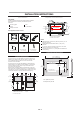
INSTALLATION INSTRUCTIONS Tools and Parts Required Cutout Dimensions Tools Needed Gather the required tools and parts before starting installation. Read and follow the instructions provided with any tools listed here. Measuring tape Pencil Phillips screwdriver 22 3/4" (57.8 cm) 1 1/16" (2.7 cm) Drill 7/64" drill bit 17" (43.2 cm) min. htdW i A 26 11/32 "(6 6.8 cm) 17 1/8"(43.5 cm) max. Parts Supplied (not shown to scale) 1 1/16" (2.7 cm) 3" (7.6 cm) B A. Trim kit frame overhang B.
Electrical Requirements Prepare Microwave Oven Attach Rails WARNING 1. Unplug microwave oven before proceeding with installation. 2. Remove any loose items inside microwave oven. 3. Carefully turn microwave oven onto its top, with the door facing forward (toward installer). 4. Align the two rails on the microwave oven bottom, as shown, making sure the flanges are forward and pointing up. Electrical Shock Hazard Plug into a grounded 3 prong outlet. A B C Do not remove ground prong.
Prepare Cutout/Cabinet Opening 5. Using a 7/64" drill bit, drill pilot holes into the three hole marks shown in the figure above. 6. Realign and install the bottom duct with three short screws. 7. Using a 7/64" drill bit, drill pilot holes through the four bottom duct flange mounting holes into the bottom front facing of the cutout/cabinet opening. 1. On the cutout floor, find and mark the centerline. 2.
2. 5. Slide the microwave oven back and into place. The mounting holes of the rail flanges and bottom duct flange will align against the bottom front facing of the cutout/cabinet opening. 6. Secure the microwave oven to the cutout/cabinet by installing four short screws into the mounting holes. Holding the trim kit frame in place, use a 7/64” drill bit to drill four pilot holes into the front facing the cutout/cabinete trhough the mounting hole guides the upper and lower corners of the trim kit frame.
SEGURIDAD DEL HORNO MICROONDAS Su seguridad y la de otras personas es muy importante. Existen muchos mensajes de seguridad importante tanto en este manual como en el dispositivo. Siempre lea y sigas todas las instrucciones de seguridad. Este es el símbolo de alerta de seguridad. Este símbolo lo alerta sobre peligros potenciales que pueden matarlo o lastimarlo tanto a usted como a otras personas. Todos los mensajes de seguridad serán precedidos por este simple y las palabras "PELIGRO" o "ADVERTENCIA”.
INSTRUCCIONES DE INSTALACIÓN Herramientas y piezas Dimensiones de recorte requeridas Herramientas necesarias Reúna todas las herramientas y piezas requeridas antes de comenzar con la instalación. Lea y siga las instrucciones proporcionadas para las herramientas listadas a continuación. Cinta de medir Lápiz Destornillador Phillips 22 3/4" (57.8 cm) 1 1/16" (2.7 cm) Taladro Broca de taladro de 7/64" htdW i 17" (43.2 cm) min. 1/8"(43.5 cm) max.
Requerimientos eléctricos Preparación del horno microondas La instalación de la Rieles PELIGRO 1. 2. 3. Riesgo de descarga eléctrica Conecte a un enchufe a tierra de tres puntas. No retire el enchufe a tierra. No utilice un adaptador. No utilice una extensión o alargador. El no seguir estas instrucciones puede provocar la muerte, incendio, o descargas eléctricas. Desconecte el horno microondas antes de proceder con la instalación.
Preparación de la abertura/gabinete 5. Utilizando la broca de 7/64’’, haga los tres 1. En el piso de la abertura, encuentre y marque la agujeros marcados en el Paso 4. línea central. 2. Coloque l a base infe rior en la ab ertura, con el soporte descansando sobre la parte delantera inferior enfrentando la abert ura. 6. Realinee e instale la base inferior con los tres B A tornillos cortos. 7.
5. Deslice el horno microondas hacia atrás para 2. Sostenga el juego de molduras del marco en su ponerlo en su lugar. Los agujeros de los soportes de los rieles y de la base inferior se alinearán contra la parte delantera inferior de la abertura del gabinete. lugar y utilice la broca de 7/64’’ para hacer cuatro agujeros en la parte delantera de la abertura/gabinete tanto en la esquina superior e inferior del juego de molduras. OBSERVACIONES: 6.
KENMORE LIMITED WARRANTY FOR ONE YEAR from the date of sale this product is warranted against defects in material or workmanship when it is correctly installed according to all supplied instructions. WITH PROOF OF SALE, return a defective product to the retailer from which it was purchased for free replacement. This warranty is void if this appliance is ever used for other than private household purposes.