
Owners manual


2
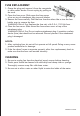
PARTS ASSEMBLY
1. Pull power cord (3) all the way out.
2. Attach rear base half (2) and front base half (5)
together by inserting the two posts on front half into
the two holes on rear half and insert the two posts
on rear half into the two holes on front half.
3. Insert the power cord through the center hole in
the base assembly. Insert the 4 posts at the bottom
of the fan body into the 4 holes on the base
assembly. Carefully turn the fan and base upside down.
Insert the four screws into the base post holes and
tighten. Fit the power cord into the three hooks on the
underside of either the front or rear base half and
through the slot in the base edge. Turn the fan upright for operation.
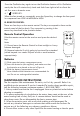
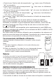
1. Fan Body 2. Rear Base Half 3. Power cord
4. Screws 5. Front Base Half 6. Receiver
Remark: Rear base half and front base half are same.
PARTS (see Figure 1)
OPERATING INSTRUCTIONS
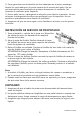
I. CONTROLS (Figure 2)
1. Remote Control Holder
2. Control Panel Keys
3. Power On/Off Indicator Light
4. Speed Indicator Lights
5. Timer Set Indicator Lights
II. CONTROL PANEL
1. “ ” ON/OFF
To turn fan on, press the “ ”
2. “ ” TIMER
Choose from 1 to 7 hour setting as follows:
• 1 hour: Press the “ ” Timer key once. The indicator “1H” will be lit.
• 2 hours: Press the “ ” Timer
• 4 hours: Press the “ ” Timer
• 7 hours: Press the “ ” Timer
Press the Timer key an eighth time to turn the Timer feature off.
3. “ ” OSC
To activate the Oscillation feature, press the Oscillatio
5
1
6
3
4
2
Figure 1
key.
KEY:
n key once.
key twice. The indicator “2H” will be lit.
key four times. The indicator “4H” will be lit.
• 3 hours: Press the “ ” Timer
key three times. The indicators “1H” & “2H” will be lit.
• 5 hours: Press the “ ” Timer
key five times. The indicators “1H” & “4H” will be lit.
• 6 hours: Press the “ ” Timer
key six times. The indicators “2H” & “4H” will be lit.
key seven times. The indicators “1H”,”2H” & “4H” will
be lit.
1
2
3
4
5
1H 2H 4H
Figure 2