Installation Instructions Instrucciones de instalaci6n EngJish / Espa_oJ Models / Modelos : 401.8504% 85143 I(e @ @ ¢ ::::,color numbe_} nOmero de color P/N DE68-03806A Sears Brands Management Corporation, Hoffman Estates, IL 60179 USA www.kenmore.com www.sears.
OF CONTE TS iMPORTANT SAFETY iNSTRUCTiONS ................. 3 READ THESE iNSTRUCTiONS COMPLETELY AND CAREFULLY. Electrical Requirements ............................ 3 * Electrical safety instructions ........................ BEFORE YOU BEGIN .............................. Hood 4 Exhaust ................................... Damage - Shipment/Installation Parts Included 3 4 .................... ................................... - Save these instructions for local inspector's use.
I SA ETYI This product requires a three-prong grounded outlet. The ELECTRICAL REQUIREMENTS installer must perform a ground continuity check on the power outlet box before beginning the installation outlet box is properly grounded. to insure that the If not properly grounded, if the outlet box does not meet electrical requirements (under ELECTRICAL REQUIREMENTS), a qualified or noted electrician should be employed to correct any deficiencies.
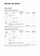
YO I HOOD EXHAUST Outside tap exhaust The following (example only_ chart describes an example of one possible ductwork installation. LENGTH EQUIVALENT DUCT PIECES Roof Cap 12 Ft. Straight Duct (6" Round) x NUMBER USED = LENGTH EQUIVALENT 24 Ft. x (1) = 24 Ft. 12 Ft. x (1) -- 12 Ft. 5 Ft. x (1) -- 5 Ft. Total Length = 41 Ft.
NOTE: If you need to install ducts, note that the total duct length of 31/_" x 10" rectangular should not exceed 140 equivalent Outside ventilation the following or 6" diameter round duct feet. MAXIMUM DUCT LENGTH: For satisfactory air movement, the total duct length of 31/_'' x 10" rectangular requires a HOOD EXHAUST DUCT. Read or 6" diameter round duct should not exceed 140 equivalent feet. carefully.
DAMAGE - SHIPMENT/INSTALLATION * if the unit is damaged in shipment, call the store where the unit was purchased_ or 1-800-4-MY-HOME * if the unit is damaged by the custemer, repair or replacement * if the unit is damaged by the installer (if other than the customer), repair or replacement arrangement is the responsibility ®. of the customer. must be made by between customer and installer.
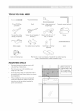
TOOLS YOU WILL NEED Pencil #1 and #2 Phillips screwdriver Ruler or tape measure and Carpenter square (optional) straight edge Tin snips (for cutting Scissors (to cut template, damper, if required) if necessary) Gloves Electric drill with 3/16", I/2" and 5/8" drill bits < Safety goggles Saw (saber, hole or keyhole) Stud finder or Hammer Level (optional) Duct and masking tape Filler blocks or scrap wood pieces, if needed for top cabinet spacing (used on recessed bottom cabinet installation
i STALLATIONS PLACEMENTOF THE MOUNTING PLATE Removing the microwave carton!removina 1. oven from the the mounting Remove the installation plate instructions, Exhaust adaptor, filters, glass tray and the small hardware bag. Do not remove the Styrofoam 2. protecting the front of the oven. Fold back all 4 carton flaps fully against carton sides. Then carefully roll the oven and carton over onto the top side. The oven should be resting in the Styrofoam.
Determining wall plate location under your cabinet Plate position - beneath fiat bottom cabinet Plate position - beneath framed recessed cabinet bottom 1/2" 30" to Cooktop Draw a vertical line on the wall at the center of the 30" Draw a vertical line on the wall at the center of the wide space. 30" space. Tape the Rear Walt Template onto the wall matching the centerline and touching the bottom of the cabinet.
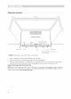
Aligning the wall plate REAR WAL_TEMPLATE Draw a Vertical Area A Centerllne notches _OoOoOoOoOoO _ Wall from "_ _* _---- Line on Center of Top Cabinet ,OoOoOeOoOoOoO 7 Hodzontal Une Area E Horizontal Hole C Hole Draw a Horizontal "Rear Wall CAUTION: Wear gloves to avoid cutting Une B line on wall from bottom of Template". fingers on sharp edges. 1. Draw a Vertical line on the wall at the center of the 30" wide space. 2. Draw a Horizontal 3.
iNSTALLATiON TYPES (CHOOSE A, B OR C) This microwave oven is designed for adaptation A. Recirculating (Non-Vented B. Outside Top Exhaust (Vertical C. Outside Back Exhaust (Horizontal to the following three types of ventilation: Ductless) Duct) Duct) NOTE: This microwave is shipped after being assembled for "Recirculating'. the filter-upper. Select the type of ventilation required for your installation And exhaust adaptor A. RECIRCULATING (NON-VENTED DUCTLESS) See page 12 \ B.
A. RECIRCULATING (NON-VENTED DUCTLESS) iNSTALLATiON OVERVIEW A1. Attach mounting plate to wall A2. Prepare top cabinet A3. Mount the microwave oven 3. Place the mounting plate against the wall and insert the toggle wings into the holes in the wall to mount the plate. NOTE: Before tightening toggle bolts and wood screw, make sure to line up bottom line of the Mounting with Horizontal Mounting CAUTION: line of "Rear wall Template" plate and then the plate is properly centered under the cabinet.
A3. Mount the microwave oven 4. Attach the microwave oven to the top cabinet. Cabinet Front Cabinet Bottom Shelf Filler Block of Cabinet FOR EASIER INSTALLATION WE RECOMMEND AND THAT TWO PERSONAL PEOPLE MICROWAVE OVEN. IMPORTANT." Do not grip or use handle NOTE: wall If your around the power NOTE: We a front overhang. if filler occur from NOTE: cord When power cord Keep it tight blocks filler are throughout cutting blocks gnlngScrew installation.
B. OUTSIDE TOP EXHAUST (VERTICAL DUCT) B1. Adapting microwave blower For outside top exhaust AFTER: Fan Blade Openings Facing Upward 1. Remove and save screw 2. that holds blower microwave. plate to / Lift up the blower plate. J Blower Plate Back of 5. "'""%_ Place the blower unit back into the opening. Microwave Screw 3. Carefully enough pull out the blower to allow you to adjust unit. The wires will extend the blower far unit. CAUTION: Do not pull or stretch the blower unit wiring.
B3. Mount the microwave oven see page 12_13. (Proceed on AI_A3) B4. Adjust the exhaust adaptor Open the top cabinet and adjust the exhaust adaptor connect to the house duct. to Back of Blower-Plate Damper Microwave __o_ te___sBtadek t he Exhaust Adaptor B5. Connecting ductwork House |. Extend as Needed the house duct down Duct to connect to the exhaust adaptor. 2. Seal exhaust duct joints using duct tape.
C. OUTSIDE BACK EXHAUST (HORIZONTAL DUCT) C1. Adapting back 1. microwave blower for outside exhaust Remove and Make sure thewiresare not pinched. NOTE: The blower unit exhaust openings should match exhaust openings on rear of microwave oven. save screw that holds blower Plate to 6. Secure the blower unit to the microwave with the screw. microwave. Blower-Plate Blower motor screw 2. Lift Blower up the Blower Plate.
YO 1. YO ICROWAV Make sure the microwave oven has been installed according to instructions. 2. Remove all packing material from the microwave oven. 3. Install turntable and ring in cavity. 4. Replace house fuse or turn breaker back on. 5. Plug power cord into a dedicated outlet. 6. Read the Owner's Manual. 7. KEEP INSTALLATION 20 amp electrical INSTRUCTIONS Insure proper ground exists before use FOR THE LOCAL INSPECTOR'S USE.
NOTE
iNSTRUCCIONES DE SEGURiDAD iMPORTANTES ....... 20 LEA ESTAS INSTRUCCIONES EN SU TOTALIDAD Y CUIDADOSAMENTE. Requisitos el_ctricos ............................. 20 * Instrucciones de seguridad el_ctrica ................ 20 ANTES DE COMENZAR .......................... Extractor de campana ........................... Da_os - Envio/Jnstalaci6n Piezas incluidas Herramientas Espacio 21 21 ........................ de instalaci6n 23 ......................... 24 INSTALACiONES ..............
S I I Este producto requiere un tomacorriente a tierra de tres pines. El instalador continuidad el_ctrica I con conexi6n debe controlar BAJO NINGUNA ALIMENTACI6N.
COM A TS ZA EXTRACTOR DE CAMPANA Extractor superior externo (_jemplo solamente) El siguiente cuadro describe un ejemplo de una posible instataci6n de la red de conductos.
NOTA: Si debe instalar conductos, conductos LONGITUD M._XIMA observe que la longitud total de los conductos rectangutares de 3 1/_- x 10" o de los DEL CONDUCTO: Para una rotaci6n de aire satisfactoria, redondos de 6" de di_metro no debe superar los del conducto rectangular la Iongitud total de 3V_" x 10" o det conducto 140 pies equivalentes. redondo de 6" de di6metro no debe exceder los 140 pies La ventilaci6n externa requiere un CONDUCTO DE equivatentes. EXTRACTOR DE CAMPANA.
DAI OS - ENVJO/INSTALACI6N * Si la unidad se daRa en el envJo, comun[quese con la tJenda donde la compr6_ o con el 1-800-4-MY-HOME * Si el diente da_a la unidad, * Si el instalador dafia la unidad (en caso de que sea una persona distinta al ctiente), la reparaci6n deben reatizarse mediante Ja reparacJ6n o eJ reempJazo es responsabilJdad deJ ®. cJJente. o el reemplazo un acuerdo entre el ctiente y el instalador.
HERRAMIENTAS NECESARIAS Destornitlador Phillips L6piz Cinta m_trica y regta Escuadra (opcionat) Taladro el_ctrico con Guantes #1y#2 Tijeras para cortar metales Tijeras (para cortar (para cortar el regulador la plantilta, si es necesario) mechas de 3/16", 1/2" y 5/8" Sierra (tipo sable_ de Detector de montantes o de tiro de humo_ si es necesario) Gafas de seguridad perforaci6n Cinta adhesiva y para conductos o de calar) Bloques de relleno o pedacitos gabinete martillo Nivelador (opci
I STALACIONES COLOCACION DE LA PLACA DE Buscar los rnontantes de pared MONTAJE Quitar el homo de microondas de la caja/ quitar [a p[aca de rnontaje 1. Retire las instrucciones de instataci6n, el adaptador extractor t los filtros t ta bandeja piezas peque_as. No quite el Styrofoam frente del horno. 2. del de vidrio y la bolsa de que protege el Pliegue las 4 solapas de la caja contra los laterales de la caja. Luego con cuidado gire el homo y la caja y ap6yelo sobre la parte superior.
i iiiiiiiiiiiiiiiill iii iiiii i!i!! !i iiiiiiii!iii!i i¸i li!iiiiiiiiiiiill !i!iiii iiili iiiiiiiii i¸i_ iil i!!i!!!i!ii! i!iii¸ !ii_ i!i ii_!!i !i!iiiii !! !iiiliil _ i¸i_!!i i¸¸ _ii iii lililililil ilil ililil ililililil ilililililil ililililililil ilililililililil ililil ililil ililililil ililililililil ilililililil ilililililililil ililil ililil ililililil ililililililil ilililililil ilililililililil ililil ililil ililililil ililililililil ilililililil ilililililililil ililil ililil ililililil ilililil
Alinear la plata de pared REAR ,_,rea A WAL_TEMPLATE Muescas de la I_nea central x'_ Dibuje una linea vertical en [a pared desde el centro dei i _r-_ superior ,! _OoOoOoOoOoO _ _OoOoOeOoOoOoO j, Linea horizontal _,rea E Orificio C Trace una I[nea horizontal Orificlo en la pared parte inferior de la "plantlila PRECAUCI6N: B Linea horlzontaI desde de la de la pared trasera", Use guantes para evitar cortarse los dedos con los bordes fitosos. 1.
i iiii;iill iii iiiii i!i!! !i 13!i i¸fIG !i!iiii iiili iiiiiiiii i¸i_ iil i!!i!!!i!ii! i!iii¸ !ii_ i!i ii_!!i !i!iiiii !! !iiiliil _ i¸i_!!i i¸¸ _ii iii lililililil ilil ililil ililililil ilililililil ililililililil ilililililililil ililil ililil ililililil ililililililil ilililililil ilililililililil ililil ililil ililililil ililililililil ilililililil ilililililililil ililil ililil ililililil ililililililil ilililililil ilililililililil ililil ililil ililililil ililililililil ilililililil ililililililili
A. RECIRCULACION (SIN VENTILACION, SIN CONDUCTOS) DESCRIPCION GENERAL DE LA INSTALACI6N A1. Sujete la placa de montaje a la pared A2. Prepare el gabinete superior A3. Instale el homo de microondas 3. Coloque la placa de montaje contra la pared e inserte las mariposas en los orificios de la pared para instalar la placa.
i iiiiiiiiiiiiiiiill iii iiiii i!i!! !i iiiiiiii!iii!i i¸i li!iiiiiiiiiiiill !i!iiii iiili iiiiiiiii i¸i_ iil i!!i!!!i!ii! i!iii¸ !ii_ i!i ii_!!i !i!iiiii !! !iiiliil _ i¸i_!!i i¸¸ _ii iii lililililil ilil ililil ililililil ilililililil ililililililil ilililililililil ililil ililil ililililil ililililililil ilililililil ilililililililil ililil ililil ililililil ililililililil ilililililil ilililililililil ililil ililil ililililil ililililililil ilililililil ilililililililil ililil ililil ililililil ilililil
B. EXTRACTOR SUPERIOR EXTERNO (CONDUCTO B1. Adaptar el ventilador para el extractor Quite y guarde del microondas DESPUES: el tornillo 2. Levante _ de las aspas del ventilador hacia arriba superior externo que suieta la plata del venfilador al microondas. Aberturas VERTICAL) plata la del ventJlador. \ Placa del ventilador 5. Parte posterior det microondas Coloque abertura. la parte trasera de la unidad de venfilador en la Tornillo 3.
i iiiiiiiiiiiiiiiill iii iiiii i!i!! !i iiiiiiii!iii!i i¸i li!iiiiiiiiiiiill !i!iiii iiili iiiiiiiii i¸i_ iil i!!i!!!i!ii! i!iii¸ !ii_ i!i ii_!!i !i!iiiii !! !iiiliil _ i¸i_!!i i¸¸ _ii iii lililililil ilil ililil ililililil ilililililil ililililililil ilililililililil ililil ililil ililililil ililililililil ilililililil ilililililililil ililil ililil ililililil ililililililil ilililililil ilililililililil ililil ililil ililililil ililililililil ilililililil ilililililililil ililil ililil ililililil ilililil
C. EXTRACTOR TRASERO EXTERNO (CONDUCTO C|. Adaptar el ventilador del microondas HORIZONTAL) s. Coloquela partetrasera0e la uni_ad0eventiladoren la abertura. para el extractor exterior posterior 1. Quite y guarde el tornillo que sujeta la plata del ventilador al microondas. DESPUES: Aberturas de Jasaspas deJ ventilador hacia atr6s Extremo A Tornillo del motor del ventilador 2. Levante la placa del ventilador.
A TS UTILIZAR EL MICROONDAS 1. AsegOrese de que et horno de microondas se instat6 de acuerdo con las instrucciones. 2. Quite todo el material 3. Instate el plato giratorio 4. Vuelva a colocar el fusible de la casa o conecte de embataje del horno de microondas. y el aro en la cavidad. nuevamente el disyuntor. 5. Enchufe el cable de alimentaci6n a un tomacorriente de 20 amperes dedicado. AsegOrese de que existe una conexi6n a tierra adecuada antes de utillzar el homo de mlcroondas 6.
NOTA