Before you begin ..................................................... 2 Location ................................................................... 2 Recommended 2 Electrical grounding requirements Exhaust requirements [] .................... ............................................ 2 ............................................. 3 Water supply and drain requirements I stalla I st ct | Laundry instructions ...................... 3 Please begin ....................................
Before Please you read begin... these against instructions all the through. way collecting _ '_ draperies screwdriver behind Replace before screwdriver or curtains relief must and be sure to keep any and all items from failing the Laundry of the or appliance Center. Laundry with Center. and 5ocket the rating install your Kenmore Laundry You need these tools to ® Center. Getthem together in one place to keep track of them. A B your responsibility.
The Maximum Length duct to exhaust the dryer. Excessive lint can system upon build up inside the exhaust system and create a fire hazard and restrict air flow. Restricted used, r,'_ Do not use plastic flexible air flow will increase drying times, if your depends number exhaust of the the of elbows hood. and The maximum both rigid and flexible chart.
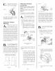
Using theposts corner four shipping (two oncarton each • side), carefully lay the Laundry Center on its left side and remove the foam shipping base. Plastic Spacer Block Mechanisrn']_4_ h,pping 1 Shipping Clips Shipping _" _/ i Hose Shipping Carton Corner Posts socket, mechanism Using tileremove ratchet with 3/8 inch • shipping bolt. Remove plastic spacer block from center of base using adjustable pliers.
Alternate installations: recessed Installation or closet The following are minimum installation spacings and openings (in inches) that you should allow. For easier installation and service, consider additional spacing.
Alternate C ® inecure Figures Standpipe, the 3hose as shown4 Tub, 5 In wall standpipe. electrical Figure 9 Clam connection Disconnect power supply cord from electric supply before making these changes. FigUreCable5 Tie _ .......... Metal Pipe Electrical ground is required on this appliance. No. 4 Copper Wire This appliance is manufactured with the neutral terminal connected to the frame.
d. Connect theneutralwireof the flexiblearmored ornonmetallic sheathed copperpowersupply cabletothecenter silver-colored terminalscrewof theterminal blockandconnect theotherwires totheouterterminals. SeeFigure 12.Forconnecting plain-end fieldwire,seeFigure15. Replace theterminal blockcover. e. Green ground screw \ ground wire Neutral Grounded neutral Figure 12 DO NOT permit connection of"the frame grounding conductor to the neutral wire of the power supply cord: a. Remove terminal block cover. b.
ROUGH-IN D_MENSIONS 25 1/4" 0 2 W2_ 16 1/4" 75 112" "b T WATER INLETS (REAR) 54 5116" "i_''_ 4 13!16" 41 114" 29 7116" I _ tl 3 3/4 _ 27" ............... 30 13/16 ..... 7116" "_ Sears, Roebuck and Co. Hoffman Estates, IL 60179 U°S.A. Made in U.S.A.
Antes de comenzar ............................................................ 2 ........................................................... 2 Lugar de instalacion Instrucciones I strucc pa la l stal [] f | recomendadas para la puesta a tierra ......... 2 Requerimientos electricos Requerimientos del sistema de escape ............................. 3 Requerimientos para el agua y el desagOe ........................ 3 Para comenzar ........................................................
Antes de comenzar... Le regames instrucciones. leer atentamenle tedas estas 4. _ador _ Vuelva a colocar todos los paneles de acceso o de servicio antes de poner en funcionamiento la Lavadora/Secadora Zdor de Punta Plana Phillips lnstrucciones recomendadas _cates de tubo puesta Nive[ sted necesita mientas para estas instalarherrasu Lavadora/Secadora Super- A O puestas Kenmore. MantOngalas todasjuntas para facilitar el uso. D Secadora Superpuestas.
]No use ductos flexibles de pBstico para el escape de la secadora. Se puede acumular un exceso de pelusas en el sistema de escape, treat un riesgo y obstruir el flujo de aire. La restriction del flujo del aire prolongara el tiempo de secado. Si su sistema de escape actual tiene ductos de pBstico o de laminas metalicas delgadas, _lacelo con un ducto met_ilico rigido o flexible. AsegOrese de que los ductos existentes no tengan pelusas antes de instalar el ducto de la secadoFa. []Si 2.
la c_tiade cartdn (2 enesquineras cada lado),de Utilizando las cuatro ® haga descansar cuidadosamente la LavadoraiSecadora Superpuestas sobre el lado izquierdo y saque la base de espuma de embarque. Bloque Espaciador de Plkstico Bloque de Sujetadoresde Embarque 11 / los de nn agna caliente y fria Dejellaves correr poco de agna de • para vaciar las lineas y eliminar las particulas que pueden obstruir las rejillas de las vfilvulas de agna.
Instalaciones alternas: instMacidn en un nicho en un armario. INCORRECTO de Instalacidn Minimo o A continuacidn se indican los espacios y aberturas minimas necesarias para la instalaci6n (en pulgadas}. Para facilitar la instalaci6n y el servicio, se recomienda agregar un poco mils de espacio.
Conexidn C yen mnestra la Fignra como 3 - Tnbo njete laenmangnera se @ de Toma: en la Fignra 4- Tina: la Figura 5 - toma de agua mural. electrica Desconecte lomacnrriente cambios. Este el corddn antes artefacto debe de a/tema e|_ctrico hacer ser puesto Figura 9 del estos Tuberia de Metal del a tierra. Este artefacto estfi fabricado con el conductor neutro conectado al bastidor.
d, Conecte el alambre neutro cable el_ctrico flexible no metfilico al tomillo del de cobreo de borne central plateado del tablero de bornes y conecte los otros alambres a los bornes externos. Cenecte el alambre separade de puesta a tierra de cebre del conector de puesta a tierra externo a una fierra aprebada. Conductor neutro no puesto a tierra Figura 13 Vet Figura 12. Para conectar el alambre de campo de extremo sencillo, vet Figura 15. Vuelva tablero a colocar de bomes.
D_MENS+ONES PARA LA +NSTALACJON 2 tl2" I 8 16 114" _J / ESCAPE ....... / 75 t/2" 519 T 54 /!6" EN]+RADA DEL AGUA (PARTE TRASERA) 4 13116" -- 41 1!4" 29 71!6" 36 It!6" q + + 11 7t16" 3 314" 30 !3116 ....... -=--_ Sears, Roebuck and Co, Hoffman Estates+ +L60179 U°S,A, Fabricado en Jos EE.UU.