
Manual


Phlliips #2 screwdriver and an adjustablewrench,
W.'I ;| _II _[_ rmlU_WmBumm
I ExcessiveWeight Hazard
Usetwo or more peoplewhen moving the wine
cooler,
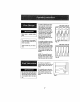
1. Unplug the wine cooler and lay the uniton its back.
2. Unscrew the two Leveling Lags; one from the
bottom hinge on rightand one from the left side of the
unit (see Fig. 3 and Fig. 4 for locations).
3. Remove the bottom hinge by unscrewing itsthree(3)
screws (Fig, 2),
NOTE; Keep this hinge tn a safe place incase
you need to return to a right hand door swing,,
4, Carefully remove thedoor and set aside by sliding
it downward off of the top hinge pin,
5, Remove the two (2) plastic screwcaps rocatad on top
of the hinge cover (Fig. 1).
6, Remove the tophinge cover by removing its two (2)
screws (Fig, 1).
7o Remove the top hinge by unscrewing its three (3)
screws (Fig. 1)
8, Remove the plasUodoor p(ncap from the top left
side of the door and transfer it tothe right side of the
door,
9, Remove the three (3) Plastic Screw Caps from the
lop left,side of the cabinetand transfer them tothe
top rightsideof the cabinet(Fig.6),
10. Installthe tophinge on the leftside of the unit and
secure with three(3) screws. (Fig, 1)
11. Install the hinge cover back on the top hinge and
secure with two (2) screws, (Fig. t)
12. instalt the two (2) plastic screw caps on the hinge
cover,_(Fig. 1)
13, Carefully install the door on the cabinet (Insert upper
door intotop hinge pin),
14. Using the left-side bottom hinge suppliedwith your
unit (FlgoS):Insert the hinge pin Into the bottom of the
door,then align the holes in the hinge with the holes
in the cabinet and secure hinge to cabinetwith three
(3) screws°
15. lnsta!l the LevelingLeg formedy attachedto the
right bottom hinge(Flgo4)onto the new left bottom
hinge, and installthe Leveling Leg from the former
left side position intothe dght side position (Fig.3),
16, Check door aflgnment, door seal and ensure the door
lock slides comfortably Into the lock chamber, Tighten
al! hinge screws,
Allow the unit to stand upright for at-least 1 hour
before putting the unit intooperation,
Fig.6
PlasticScrew Ca
Fig,1
Top Hinge
Assembly
og
Fig° 2
Right Bottom
Hinge Assembly
¸
Flg,5 ! J
Left Boftom
Hinge Assembly ............
Flgo4
8 LevelingLeg for Bottom Hinge