® Use & Care / installation Manual cocina Manual de uso y cuidado /instalaci6n Models Modelos 233.50941590 233.50944590 233.50949590 (24" wide- 233.51040590 233.51041590 233.51044590 233.51049590 (3O" wide (3O" wide (3O" wide (30" wide - 233.51141590 233.51144590 White) (24" wide - Biscuit) (24" wide - Black) 233.51540590 233.51544590 233.51545590 Stainless) White) 233.51640590 Biscuit) 233.51645590 Black) 233.51648590 233.51649590 233.
SECTION ..................................................................... PAGE Warranty .............................................................................. 2 Safety Instructions 2 ............................................................... Operation ............................................................................. 3 Cleaning .............................................................................. Parts Included With Hood .........................................
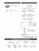
_ HI FAN LO MGHT Fan The 3-position rocker switch (on the left) controls the fan. The left position is high speed, center position is off, and right position is low speed. Light The 2-position rocker switch (on the right) controls the lights. The left position is on and the right position is off. WARNING: To reduce the supply risk of electric disconnect from power before shock, cJeanrag. ABuminum mesh filter Clean frequently using hot water and a mild detergent or in your dishwasher.
Aluminum Light Bumb (75 W Maximum) (1 per hood) Purchase Iocally. Grease F{mter OPTmONAL PARTS (purchase separateJy) CBean Cooking Filter (Non-ducted hoods only) (1 per hood) Sears Part No. 97007696 Parts Bag (4 hood mounting screws inside) Non-Ducted Kit (For use with 3¼" x 10" Duct) dncludes 3¼" x 10" Damper & 'Vent Cover) Sears Part No. 59102 74rich Round Damper (For use with 7-inch Round Duct) Sears Part No. 59183 SpBashpmate Sears Part Nos.
Kenmore rangehoodsaredesigned toperform efficiently whenattached toIongrunsofduct.Asa pointofreference, thishood wiIIfunction atapproximately 80%ofitsratedairftowwhen200equivalent feetof7"roundductwork isattached. Usethischart tocalculate theequivalent duct length of your system. Broan Model 428 3¼-in° x lO=in. Right=angBe Embow Equivalent Iength (6-ft= w/o damper) 2ft. D 0 Broan Modem 406 Straight Duct 64n. round × 2-ft, long Equivalent length 2 ft. ( 0 Broan Modem 407 Straight Duct 7-in.
1. Determine whether hood will discharge vertically (3¼" x 10" or 7" Round), horizontally (3¼" x 10" only) or nonducted. ROOF CAP 3¼" X 10" or 7" ROUND DUCT (For vertical discharge) For vertica! or horizonta! discharge, run ductwork between the hood location and a roof cap or wall cap. For best results, use a minimum number of transitions and elbows. HOUSE WIRING or Back of hood) I 24" - 30" ABOVE 3¼" X 10" DUCT (For horizontal discharge) COOKINGSURFACE 2.
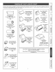
1. Remove _ from nose of hood. SHiPPiNG TAPE 2. Remove WiringCover from inside the hood. Set cover and mounting screw aside. if hood is to be installed Non-Ducted: e Purchase a Non-Ducted Kit, containing one C_ean Cooking Filter. e _nstaH the Clean Cooking Filter behind the aluminum mesh filter. e Skip to Step 6.
4. Attach 3%" x 10" Damper/Duct Connector over knockout opening. Make sure damper Pivot is nearest to W/Back Edge of hood. Remove any shipping tape from damper flap. 3V4" x 10" DAMPER/DUCT CONNECTOR 5. Instal! Vent Cover over louvers at the front of hood. Insert Tabs into top louvers, rotate cover downward, and snap cover into bottom louvers. PIVOT VENT COVER / TABS 6.
WARNING: To reduce the risk of shock, make sure power is switched service panel. Lock or tag service prevent power from being switched dentally. HOUSE WIRING (120 VAC) eJectric off at the panet to on acci- 1= Connect House Wiring (120 VAC) to hood. Use a piece of Cardboard to protect the cooktop, if necessary. A Cord Kit is avaimable = which enables the hood to plug into a standard 120 VAC wall outmeto See page 4 for Cord Kit information.
Slide hood towards until mounting screws are engaged [ 1Hang hood from _watI 4_ Mount,n_ _from parts bag_ !i!ili_i!i!_!'_!_! i in narrow end of (4) _homes. Tighten mounting screws securely. CAUTION: Do not push on filter or fan blade! Pushing on the filter or fan bmade may cause them to interfere with other hood parts. KEYHOLE (4) DUCT TAPE MOUNTING SCREW (4) 3¼" x 10" DUCTWORK 2. Connect ductwork to hood. 5094, 5104, & 5114 Models use 3¼" x 10" Ductwork.
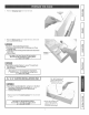
13 .14 12 1 2 10 5094 5104 5114 PART NO. 5154 5164 5174 PART NO. 98006621 99170245 98006621 99170245 99270987 99110437 97011217 99270987 99110437 97011217 99020272 99260428 99020272 99260428 98005568 97012248 98005568 97012248 97006931 99420472 97010709 ........ 99030315 97006931 99420472 97010709 99090989 99030315 ........ 99030316 14 99030310 15 97005678 99030310 99030311 97005678 16 99150471 99150471 99043200 99043200 KEY NO, 3 4 5 lO 11 12 13 *Standard Hardware.
SECCION ................................................................ PAGINA Garantfa ............................................................................. 12 Instrucciones de seguridad .............................................. 12 Operacibn .......................................................................... 13 Limpieza ............................................................................ 13 Piezas incluidas con la campana ....................................
ADVERTENCIA: Para reducir eJ riesgo de una descarga eJ_ctrica, desconecte el suministro et_ctrico antes de tirnpiar ta unidad. HI FAN LO LIGHT Ventilador El interruptor oscilante de 3 posiciones (de la izquierda) controla el ventilador. La posici6n hacia Ia izquierda es la velocidad alta, la posicJ6n central es apagado y Ja posici6n hacia la derecha es la velocidad baja. Luz El interruptor oscilante de 2 posiciones (de Ja derecha) controla las Iuces.
FHtrodegrasadealuminio (MAximo 75W) BombiHa deBuz (1potcampana) Compre Iocalmente. (_ PIEZAS OPTATmVAS (cornpra separada} Filtros mimpios para cocina (s61o campanas sin condacto) (1 por campana) Piezas Sears No. 97007696 (4tornilIos demontaje Bolsadepiezas delacampana, adentro) Kit sin conducto (Para uso con conducto de 3V4" x 10") dnciuye regulador de tire de 3V4" x 10" y tapa de ventilaci6n) Pieza Sears No. 59102 Regulador de tiro redondo de 17.8 cm (7 puNgadas) (Para use con conducto redondo de 17.
Lascampanas decocinaKenmore fueron disef_adas parasudesempe_o eficiente cuando seIassujetaa largos recorridos de conducto. Como punto de referencia, esta campana funcionara a aproximadamente el 80% de su fiujo de aire nominal cuando se le sujeta 61 m (200 pies) equivalentes de conducto redondo de 17=8 cm (7")= Utilice esta cuadro para calcular el largo equivalente de conducto de su sistema= Modemo Broan 428 3¼-pumg.
Determine siIadescarga deJacampana seraverticaI (8.3 cmx25.4cmo17.8cmredondo [3V4"x 10" o 7" redondo]), TAPA DE TECHO horizontal (8.3 cmx 25.4 cm [3W' x 10"] solamente) o sin conducto. En el case de descarga vertical u horizontal, tienda los conductos entre e! Iugar donde se instaIar_ la campana y el tap6n de techo o el tap6n de pared. Para obtener Ios mejores resuItados, utilice una cantidad minima de transiciones y codes. 8.3 cm x 25.4 cm o CONDUCTO REDONDO DE 17.
1. Retirarla cinta adhesiva de embarque de la punta de la CINTA ADHESIVA oampana, Ca 2. Quite la tapa demcabmeado del interior de Hacampana. Coloque la tapa y el tornillo de montaje a un lade. Si se instalar& macampana sin conductos: e Cornpre un kit sin conductos que contenga un fHtro de cocina lirnpio. e InstaBe el filtro de cocina mirnpio detras del filtro de maria de a_urninio, e Continue con empaso 6° Vea la p_gina 4 para informaci6n sobre el Kit sin Conducto.
SOLO PARAmNSTALACmONESCON ! CONDUCTOSDE 8.3 X 25.4CM (314 X 10") ! PARTE SUPERIOR/ POSTERIOR 4. Coloque agujero ciego. et conectador AsegOresede_ dereque e! _ de! regulador de tiro 8.3 quede × 25,4 Iocm mas(31A cercaxQuite posibb 10 ) la sobre del laadhesiva abertura superior/ posterior de la campana. cintaborde dedel la abta del regubdor de tiro. _ "d _ o , _y _, /_c_'_ j_ _,_ - ::!_ 8.3 x 25.4 cm CONECTOR DEL REGULADOR DE TIRO/CONDUCTO 5.
CABLEADO DE LA CASA (120 VCA) ADVERTENCIA: Para reducir el riesgo de descargas electrica$, aseg(_rese de apagar el interruptor de aHrnentaciSn el_ctrica en e! panel de servicio. BJoquee o _otuJe eJ paneJ de servicio para evitar que aiguien conecte accidentaJmente la energ{a electrica. 8 T, 1= Conecte el cabteado de la caea (120 VCA) a la campana. Si fuera necesario, use un pedazo de carton para proteger la superficie de la estufa.
1.Cuelgue iacampana de!os(4)tomiffosde rnontaje (que se encuentran en la bolsa de piezas). Desiice la campana hacia [a pared hasta que los tomiiios de montaje queden conectados en el extreme angosto de los (4) orificios tipo bocalmave. Apriete fijamente los torniHos de montaje. PRECAUCION: iNo presione e[ fi[tro o [a paJeta de[ ventilador! El empujar e[ fiitro o [a paIeta de[ ventiIador puede hacerla interferir con otras piezas de [a campana.
13 .14 12 ¢# 1 2 10 O, 5094 5104 5114 P_EZA NO. 5154 5164 5174 P_EZA NO. 1 2 98006621 99170245 98006621 99170245 3 4 5 99270987 99110437 97011217 99270987 99110437 97011217 6 7 99020272 99260428 99020272 99260428 8 9 98005568 97012248 98005568 97012248 10 11 12 97006931 99420472 97010709 13 99030315 97006931 99420472 97010709 99090989 99030315 CLAVE NO.
Your iiiiiiiiiiiiiiiiii iiiiiiiiiiiiiiii!: iiiiiiiiiiiiiiii!: iiiiiiiiiiiiiiiii:i iiiiiiiiiiiiiiiiii Home ::::::::::: For repair-in your home-of all major brand appliances, lawn and garden equipment, or heating and cooling systems, nomatterwhomadeit, nomatterwhosold it! iiiiiiiiiiiiiiiiii iiiiiiiiiiiiiiiii iiiiiiiiiiiiiiii iiiiiiiiiiiiiiii iiiiiiiiiiiiiiii iiiiiiiiiiiiiiiii iiiiiiiiiiiiiiiii iiiiiiiiiiiiiiiii:i iiiiiiiiiiiiiiiii: I iiiiiiiiiiiiiiiii:i iiiiiiiiiiiiiiiii:i Forthe replacementparts, a