® Use & Care / installation Manual cocina Manual de uso y cuidado /instalaci6n Models Modelos 233.52340590 233.52344590 233.52345590 (3o" wide - Stainless) (30" wide - Bisque) (3o" wide - White) 233.52540590 (42" wide - Stainless) 233.52544590 (42" wide - Bisque) 233.52545590 (42" wide - White) 233.52349590 (30" wide - Black) 233.52549590 (42" wide - Black) 233.52440590 233.52444590 233.52445590 233.
SECTION ..................................................................... PAGE Warranty .............................................................................. 2 Safety instructions ............................................................... 2 Operation ............................................................................. 3 Cleaning .............................................................................. 3 Parts included With Hood ................................................
[_ON BLOWER sPEEol WARNING: from To reduce risk ofbefore electriccleaning. shock, disconnect powerthe supply Aluminum V ON L,GHT Speed Infinite speed slide control controls blower speed. Slower Turns the blower "ON" and "OFF". When the blower is turned "OFF", the speed control remains at the preset speed. When the b!ower is turned on again, it will return to the previously chosen setting. Light Turns the light "ON" and "OFF". First position turns on both bulbs for normal lighting.
Amuminum Grease Fimters (p_) (75 W Maximum) Light (2 per Bulbs hood) Purchase locally. OPTmONAL PARTS (purchase separateJy) Damper / Duct Connector (For use with 3¼" x 10" duct) NonoDucted Filter Kit (Clean Cooking Fiiter) (2 per hood) Sears Part No.
Kenmore rangehoodsaredesigned toperform efficiently whenattached toIongrunsofduct.Asa pointofreference, thishood wiIIfunction atapproximately 80%ofitsratedairftowwhen200equivalent feetof7"roundductwork isattached. Usethischart tocalculate theequivalent duct length of your system. Broan Model 428 3¼-in, × 10-in, Right-angme Embow Equivalent length 64n. Round Wall Cap Equivalent Sears Modemlength 59691 _ 34 ft. 8.5 ft. Broan Modem 401 Straight Duct 3¼qn. × 10qn.
1. Determine whether hood will discharge vertically, horizontally, or non-ducted. For vertical or horizontal discharge, run ductwork between the hood location and a roof cap or wall cap. For best results, use a minimum number of transitions and elbows. ROOF CAP 3W' X 10" DUCT For vertical discharge) HOUSE WIRING or Back of hood) CAP 3W' X 10" DUCT (For horizontal discharge) 2. Use these diagrams for proper placement of ductwork and electrical cutout in cabinet or wall. For a nomducted hole.
Remove and discard: _ from nose of hood, Protective Plastic from light lens, and Cardboard FHler from bottom of hood. PROTECTIVE PLASTIC --_, Remove and set aside: Damper / Duct Connecter. SHiPPiNG TAPE / DAMPER/DUCT CONNECTOR CARDBOARD FILLER 2. Remove Bottom Cover from hood. Set cover and mounting screws aside. :S BOTTOM COVER 3. Remove Wiring Cover from hood. Set cover and mounting screw aside. ¢e :S S" WiRiNG COVER 4. Remove either top or back Wirinq Knockout approved Electricam Cabme Cmam£.
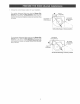
1. Choose thecorrectblowerposition foryourinstaIlation. Forvertical discharge: MakesurethattheBmower Dis+ chargA lines up with the Duct Opening in the top of the hood. Lift up the blower, slip the b!ower mounting rods into brackets on blower and tighten knurled nuts securely+ Plug in blower. BLOWER MOUNTING ROD BLOWER J DISCHARGE Vertical discharge For horizontal discharge: Make sure that the Blower Dis+ charg#_ lines up with the Duct Openin_ in the top of the hood.
2, Remove appropriate of hood, Duct Knockout(s_ TOP RECTANGULAR DUCT KNOCKOUT (Remove for 3¼" x 10" vertical dJsc,#arge) from top or back REAR RECTANGULAR DUCT KNOCKOUT (Remove for 3X" x 10" horizenta! discharge) TOP/BACK EDGE 3= Attach 31A" × 10" Damper/Duct Connector over knockout opening. Make sure damper Pivot is nearest to W/Back of hood.
1. Re@osition the btower for nomducted discharge. Move the Blower Mounting Rods to the Front Holes in the hood support channels. Position the blower so that it lines up with the Louvered Opening on the hood front. Slip the blower mounting rods into brackets on blower and tighten knurbd nuts securely. Plug in blower. FRONT BLOWER HARGE il BLOWER MOUNTING ._"_ x_/ I '' c-_N i-_'_ 1 1,// //-_-_ lit. / ./_ y'_ ROD _ It- //.-._ '_ --_"-. ,XK L.._ __:_ Non-ducted LOUVERED i ..... J ........
HOUSE WIRING (120 VAC) WARNING: To reduce the risk of electric shock, make sure power is switched off at the service panel Lock or tag service panel to prevent power from being switched on accidentally. 1. Connect House Wiring (120 VAC) to hood. Use a piece of Cardboard to protect the cooktop, if necessary. A Cord Kit is available - which enables the hood to plug into a standard 120 VAC wail outmet. See page 4 for Cord Kit information.
Hanghoodfrom(4)Mountin_ (frompartsbag). Slidehoodtowards walluntilmounting screwsareengagedinnarrow endof(4)_. Tighten mounting screws securely. CAUTION:Donot pushonfilter or fan blade! Pushingonthefilterorfanblademaycausethem tointerfere withotherhoodparts. 2. Connect Ductwork to hood. Use Duct Tape to make joints secure and air tight. LIGHT LENS LEGS 3. install 75 W Maximum Liq_ht Bumbs. Purchase bulbs Iocally. Gently squeeze _qht Lens LeAs to remove and replace lens.
5, Replace Bottom Cover. DUCTED HNSTALLATHONS ONLY 6. Install aluminum grease filters. Push filters up into recess at top of hood. Swing filters in and pull down. Make sure that Tab on filter is toward outside and bottom of hood. DOWN (3") SWING IN _ BOTTOM COVER PUSH IN @ TAB 2 6. Install non-ducted filter assemblies. Push filter assemblies up into hood. Fle×ible FBap_on filters will flex against top sides of opening. Push assemblies up until bottom of assembly clears lip on Bottom Cover.
KEY NO.
23 22 7 1 13 15
SECCIQN ................................................................ PAGINA Si dentro de 1 aho de la fecha de la instalaci6n, cualquier parte de esta campana de cocina deja de funcionar en forma apropiada debido a defecto en el material o mano de obra, Sears reparar_ la pieza afectada o proveer_ e instalar_ una pieza nueva sin cargo.
_ON BLOWER ++II,,, ADVERTENCIA: Para reducir eJ riesgo de una descarga et_ctrica, desconecte el suministro et_ctrico antes de timpiar ta unidad. F{mtros de maria de aBuminio Limpie frecuentemente los filtros con agua caliente y un detergente suave. Los filtros se pueden lavar en lavaplatos. Se debe lavar Ios filtros de malIa de aluminio aproximadamente cada rues, dependiendo de su use.
F{mtres degrasadealuminie l_aximo 75de '7,/) BombiHas luz per campana) Adquieralas Iocalmente. PIEZAS OPTATmVAS (compra $eparada) Conector deregumador de tiro/conducto (Parausecon un ductode 8.3x25.4cm[3¼"x10"]) Equipo de fimtros sin conductos P]aea posteiror Piezas Sears Nos.
Las campanas de cocina Kenmore fueron disehadas para su desempef_o ÷ficiente cuando se las suieta a largos recorridos de conducto, Como punto de referencia, esta campana funcionara a aproximadamente et 80% de su fluio de aire nominal cuando se le sujeta 81 m (200 pies) equivalentes de conducto redondo de 17,8 cm (7"), Utilice esta cuadro para calcular e! largo equivalente de conducto de su sistema, Modelo Sears 59691 8-pulg.
1. Determine si la descarga horizontaI o sin conducto. de Ia campana ser_ vertical, TAPADETECHO CONDUCTODE 8,3 cm x 25.4 cm En el case de descarga vertical u horizontal, tienda los conductos entre e! Iugar donde se instaIara la campana y el tap6n de techo o el tap6n de pared. (Para descarga vertical) Para obtener Ios mejores resuItados, utilice una cantidad mfnima de transiciones y codes. CABLEADO ELECTRICO LA CASA (Parte superior de la campana) _TAPON t 45.7 cm a 60.9 cm 3.
Retire y deseche: Lacinta de embalaie de Ia nariz de la campana, el pmastico de protecci6n del Iente de Iuz y el relleno de carton de la parte inferior de la campana. Retire y fije aparte: Conector de regumador de tiro/ conducto. PL/_STICO DE PROTECCION 8 CINTA DE EMBALAJE CONECTOR DE REGULADOR DE TIRO/CONDUCTO RELLENO DE CARTON Ca 2. Retire la cubierta inferior de Ia campana. Coloque la tapa y los torniilos de montaje a un lado. O, CUBIERTA iNFERiOR 3.
1. EscojaIa posici6ncorrectadel ventiladorparasu instalaci6n. ABERTURA DEL DUCTO Paraunadescarga verticaE: Aseg0rese dequeladescarga dem ventHador estealineada conIaabertura deBducto en la parte superior de la campana. Levante eI ventilador, deslice Ias barras de montaje deI ventilador dentro de las escuadras en el ventilador y apriete las tuercas firmemente. Conecte el ventilador.
AGUJERO CIEGO DEL CONDUCTO RECTANGULAR SUPERIOR 2. Quiteel paralosconductos apropiados delapartesuperior odelaparteposterior de lacampana. (Quite para descarga vertical de 8.3x25.4 cm [3X" x 10"]) 8 T, Ca AGUJERO CIEGO DEL CONDUCTO RECTANGULAR POSTERIOR (Quite para descarga horizonta/ de 8.3x25.4 cm [3X" x 10"]) 3. Coloque et conector de_ regumador de tiro/condueto de 8.3 x 25.4 ¢m (31A" × 10"_ sobre Ia abertura del agujero ciego.
ORIFIOlO FRONTAL 1, Vuelvaa colocarelventiiador parala descarga sin conducto. Mueva lasbarrasdemontajedel soplador hacia los DESCARGA DEL orificios frontames en los canales de soporte de la campana. Coloque el ventilador de manera que se encuentre atineado con la abertura de persiana en la parte fronta! de Ia campana. Des!ice Ias barras de montaje det ventilador hacia las escuadras det ventilador y apriete las tuercas firmemente. Conecte el ventilador. ] L ............. J .........
CABLEADO DE LA CASA (120 VCA) ADVERTENCHA: Para reducir eJ riesgo de descargas et_ctricas, asegQrese de apagar eJ interruptor de aHmentaci6n el_ctrica en el paneJ de servicio. BJoquee o rotule el panel de servicio para evitar que alguien conecte accidentaJmente ta energ_a eJ_ctrica. 8 1. Conecte el cableado de Bacasa (120 VCA) a Ia campana. Si fuera necesario, use an pedazo de cart6n para proteger la superficie de la estufa.
1. Cuelgue Iacampana deIos(4)tornHIos de montaje (que se encuentran en Ia botsa de piezas). Deslice la campana hacia la pared hasta que Ios tornillos de montaje queden conectados en e! extreme angosto de los (4) odfieioe tipo boeaHave. Apriete fijamente los tornillos de montaje. ORIFIOIOTIPO BOCALLAVE (4) TORNILLO DE MONTAJE (4) ...................... PRECAUC_ON: iNo presione sobre Ba paleta deB ventilador! El empujar la paleta puede hacerma interferir con otras piezas de maeampana, 2.
8 5. Vuelva acolocar lacubiertainferior. 6. Instale filtros de grasa de aluminio. Empqe los filtros hacia arriba dentro del hueco en la parte superior de la campana. Batancee los filtros hacia adentro y jab hacia aba]o. AsegQrese de que la etiqueta en el filtro se encuentra hacia afuera y hacia la parte inferior de la campana. JALE HACIA ABAJO (s3-) ca iNFERiOR EMPUJE HACIA ADENTRO_}} ETIQUETA ca 6. Instale Ios montajes deI filtro sin conductos.
CLAVE NO. PIEZA NO.
1 13 29
iiiiiiiiiiiiiiiiiiiiiu_ .....