[ Owner'sManual MODELNO. 3E W.65 3EW. 75 3EWI';O0 4EW.90 4EWl ;25 4EW1.50 5EWl.20 5EW1.75 5EW2.00 Off-Fired Hot Water Boiler • Installation CAUTION Read aft instructions carefully before starting the installation. Save this manual for reference.
KENNMORE CAST IRON BOILERS FULL ONE YEAR WARRANTY ON HOT WATER AND GAS STEAM CAST IRON BOILERS For one (1) year from the date of installation, when this boiler is installed and maintained in accordance with our instructions. Sears will repair defects in material or workmanship in the boiler, free of charge.
INTRODUCTION The Empire Water Water boiler nipples. boiler is available is a natural draft oil fired hot water with 3, 4, or 5 cast iron sections. boiler These comprised sections of cast iron sections. are held together The Empire by cast iron push The Empire Water boiler is capable of firing #2 fuel oil from 0.65 gph up to 2.00 gph.
BOILER BOIIiR Wlill MOI)EI.NO WIIIIOU IANK[ISS ('Oil niw (_5I ¸ I IANKIESS ('OIl 3[!W65Z - RATINGS NO INPUI **llliA'[ Sli(' +M[_II ( APA('IIY *MBH AND CAPACITIES NET I=B:R RA'I IN(i ING DIMENSIONS HRING RA'II_ A t: tJ I _+ (inches) MINIMUM CHIMNEY *MBH +GPH SIZE / HEIGHT A B C 3 91 80 70 0.
RULES FOR SAFE INSTALLATION AND OPEIL_TION 1. Read the Owner's Manual for Safe Operation carefidly. Failure to tbllow tile rules tbr sale operation and the instructions can cause a malflmction of the boiler and resuh in death, serious bodily injury, and/or property damage. 2. Check your local codes and utility requirements before installation. The installation nmst be in accordance with their directives, or follow NFPA 31 - Installation of Oil Burning Eqnipment, latest revision. 3.
BEFORE Complete A. Check all of the following prior to installing to be sure you have selected YOU START the boiler. the right size boiler with the proper capacity. The I=B=R rating of the boiler selected should be greater than or equal to the calculated peak heating load (heat loss) for the building or area(s) served by the boiler and associated hot water heating systems. See boiler rating and capacity table previously listed in this manual.
ALWAYS BUI_NER KEEP TILE NL_NUAL FUEL SUPPLY IS SHUT DOWN FOR AN EXTENDED I_NSTALLATION ELECTRIC LINE VALVE SHUT OFF, IF THE PERIOD OF TIa_clE.
FRESH Be sure to provide combustion enough and assures AIR FOR COMBUSTION fresh air for combustion. Enough air ensures proper WARNING that no hazard will develop due to the lack of oxygen. If you use a fireplace or a kitchen I outside air intake. These devices or a bathroom exhaust will rob NOTE the boiler fan, you should and water heater install I an of combustion air. [ You must provide enough flesh air to assure proper combustion. The fire in the boiler uses oxygen.
B. All Air from Outdoors: The confined space shall be provided with two permanent openings, one commencing within 12 inches of the top and commencing within 12 inches of the bottom of the enclosure. The openings shall communicate directly, attic) that freely communicate with the outdoors. or by ducts, 1. each When directly one square 2. When communicating inch per 4,000 communicating When communicating Btu per hour of total input with the outdoors flee, area of one square enclosure. 3.
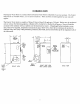
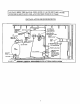
SYSTEM PIPING When the installation of the boiler is for a new heating system, first instal! all of the radiation units (panels, radiators, baseboard, or tubing) and the supply and return mains. After all heating system piping and components have been installed, make final connection of the system piping to the boiler. It is recommended to mount the circulating pump on the supply side piping, such that it pumps away from the expansion tank. Refer to the figures on the next pages. I. 2.
SYSTEM PIPING ARRANGEMENT ZONING WITH ZONE VALVES > CIRCULATOR AWAY FROM > PIPING ON SUPPLY PIPING EXPANSION TANK ARRANGED FOR "POWER PUMPS P[VRGING" AIR OUT OF SYSTEM PIPING, REFER TO THIS MANUAL'S SECTION ON "FILLING THE SYSTEM _,VITH WATER" OPTION #1 BALANCINGVALVE ZONE VALVE RETURNFROM SYSTEM IT I RAIN VALVE FOR POWER PURGING SUPPLY TO SYSTEM MAIN SHUTOFF VALVE CIRCULATOR PUMP FILL VALVE _.
SYSTEM PIPING ARRANGEMENT ZONING WITH CIRCULATORS CIRCULATOR AWAY FROM ON SUPPLY PIPING EXPANSION TANK PUMPS PIPING ARRANGED FOR "POWER PURGING" AIR OUT OF SYSTEM PIPING, REFER TO THIS MANI_AL'S SECTION ON "FILLING THE SYSTEM WITH WATER" OPTION #1 BALANCINGVALVE FLOW CHECK VALVE _ 7 ZONE CIRCULATOR _I ISOLATIONVALVE RETURNFROMSYSTEM [ _ DRAINVALVE FOR POWER PURGING MAIN SHUTOFF VALVE SUPPLY TO SYSTEM AUTOMATIC FiLLVALVE SUPPLY TO SYSTEM SHUTOFF VALVE BOILERSERVICE FILLTROLWITH AIR PURGER _Q
SYSTEM PIPING ALTERNATE DIAPHRAGM > EXPANSION CIRCULATOR PER THIS THIS ON SUPPLY MANUAL, PIPING TANK USE OPTION ARRANGE_IENT NEAR MOUNTED PIPING ARRANGEMENT PUMPS BOILER OFF THE AWAY #2 IN "FILLING PIPING BOILER FROM EXPANSION THE SYSTEM CAN BE USED WITH TANK WITH \VATER" ZONE VALVES OR ZONE CIRCULATORS SHUTOFF VALVE RETURN FROM SYSTEM ---BOILERSERVICE SUPPLY TO SYSTEM CIRCULATOR PUMP ISOLATION VALVES SHUTOFF VALVE BOILERSERVICE AUTOMATIC FILLVALVE © AOUASTAT / FILLLINEWI
7. Boilers may be factory packaged with a tanMess heater coil see figure below. This coil provides instantaneous heating of water for domestic use - if proper burner and water supply line controls are used. Tankless coils are meant to provide domestic hot water for intermittent draws, no_J continuous flow.
8. Antifreeze addedto boilers must be non-toxic, and b_ydronic heating systems. Under no circumstances in any boiler may reduce capacity by 10% or more performance will fall as concentration of antifreeze tables in this manual. BOILER WATER Volume 9.6 11.6 4 I VOLUMES STEEL PIPE FACTOR Y2" 82.5 63.5 ¾" 40.0 36.0 1" 23.3 22.2 1-1/4" 15.3 12.8 1-1/2" 10.8 9.5 6.2 5.8 SIZE 2" 13.
accordance with applicable provisions of INSTALLATION OF OIL BURNING NFPA-31 - latest revision, provisions of local shall building I EQUIPMENT, or oil-fired boilers for connections to ventsand or applicable chimneys, vent installations be incodes. CHIMNEY AND CHIMNEY CONNECTIONS This is a very important part of your heating system. No boiler, however efficient its design, can perform satisfactorily if the chimney that serves it is inadequate.
TYPICAL CHIMNEY CONNECTION MUST BE REQUIRED MINIMUM HEIGHT• MUST RE AT LEAST 3 FT. HIGHER THAN HIGHEST PART QF PASSAGE THROUGH ROOF. MUST BE AT LEAST 2 FT. HIGHER THAN ANY NEIGHBORING OBJECT. MUST HAVE AN UNOBSTRUCTED TOP OPENING. MUST BE AT LEAST 4 INCHES THICKAND BE TIGHT. MUST SLOPE UP AT LEAST 1/4 INCH PER FOOT OF HORIZONTAL RUN DRAFT REGULAT( VANE TIGHT, SMOOTH, CORRECTLY SIZED. I I ! CRIMPEDENO BALANCED DRAWBAND LAST PIECE INSTALLED WEIGHT • SEALED IN THIMBLE .
ELECTRICAL CONNECTIONS Thermostat Install a 24-volt thermostat (not provided) in a proper location. The location of the thermostat has an important effect on boiler system operation. BE SURE TO FOLLOW THE INSTRUCTIONS INCLUDED WITH THE THERMOSTAT. Grounding Permanently ground the boiler according to local codes and the National Electrical Code. Run a 14 gauge or heavier copper wire from the boiler to a grounded connection in the service panel or a properly driven and electrically grounded ground rod.
SE_/ARS KENNMORE CAST IRON BOILERS FULL ONE YEAR WARRANTY ON HOT WATER AND GAS STEAM CAST IRON BOILERS For one (1} year from the date of installation, when this boiler is installed and maintained in accordance with our instructions Sears will repair defects in material or workmanship in the boiler, free of charge.
MAIN AIR VENT: for down flow systems Before a system is filled with water, there or diaphragm is air in the pipes trapped as the system is filled. It is possible to eliminate radiation units• A main air vent will speed and simplify on the highest point AUTOMATIC in the supply FILL VALVE main when all radiation type expansion and radiation tanks (not provided) units• Some of the air will be most of this air through the air vents on the this process.
FILLING HOW A HOT The entire is heated, water WATER heating SYSTEM system it is circulated in the radiation arrangement THE OPERATES piping, and radiation from the top of the boiler units provides FILLING (boiler, flows back through positive SYSTEM THE BOILER and rapid WITH units) through the return response is filled the supply piping with water. main through As the water to the radiation the return main in the boiler units. The cooler into the boiler.
BECKETT _BOILER OIL BURNER, FIRING NOZZLE, AND AIR SETTINGS AIR SHUTTERIBAND STATIC PLATE OIL BURNER 10/0 10/2 3-5/8 3-1/2 3-1/2 AFG F-HEAD AFG F-HEAD AFG F-HEAD NO NO NO 8/0 10/0 10/2 3-1/2 3-3/8 3-3/8 AFG F-HEAD AFG F-HEAD AFG F-HEAC NO NO NO 10/1.5 10/4 10/5 2-3/4 2-3/4 2-3/4 AFG 50 MD AFG 50 MD AFG 50 MD MODEL DELEVAN OIL NOZZLE RATE (gph) HEAD-ADJ. OR SETTING LOW FIRE BAFFLE 3EW 65* 3EW.75 3EW1.00 0.50-80°B 0.65-70°B 0.85-70°B 0.65 0.75 1.
NOZZLES AND ELECTRODES: Use the proper size, spray angle, and spray pattern nozzle. Refer to the recommended nozzle selection charts at the end of this manual. To install a nozzle, remove the nozzle line electrode assembly, if necessary remove the retention ring assembly, and then install and tighten the nozzle. Be careful not to damage the electrode insulators or the bend the electrode tips. After installing the nozzle, reassemble the nozzle line electrode assembly and set the electrode tip spacing.
BECKETT AFG BURaNER ELECTRODE BOILER MODEL 5EW DIMENSION ADJUSTMENTS "'N" (electrode to nozzle) 1/16" lMENSION VARIABLE DIMENSION (VI) HEADS "H" (head to nozzle) 7/32" to 9/32" "}'1" SEE BELOW--\_ 5132 GAP LI or VI ,,. .._.._CTROOE " " _ ..,a HEAD _.. _DIMEMBION -N" E B£LOW BECKETT AFG VARIABLE (V1) HEAD ADJUSTMENTS AND SETTINGS _Lfrl LOC:I w&Ja4_ /_" s_JUST,UK.( ).4[A0 A_lr T'Jll.
5/32" - 4 mm ,)5/64" to 7/64" or 2 to 2.
CHECKING A boiler Relay using (refer a tankless back coil is configured to the SYSTEM configured with a Honeywell included with the boiler. IMPORTANT ADJUST AND with a Honeywell PIPING L8148A section CONTROLS: CONTROLS L8124C for more details). Hi Limit Aquastat - You or your OPERATING ADJUSTING installer Relay.
MAINTENANCE ANUALLY: To assure trouble-free operation, it is recommended that the flue passages, combustion chamber area (target wall, fire door insulation, durablanket), burner adjustment, operation of the controls, and boiler seals (fire door gasket or silicone seal, cast iron sectional seals, flue collector) be checked once each year by a competent Service Technician.
OIL OIL I. 2. 3. 4. 5. 6. 7. 8. 9. BOILER BOILER / BURNER CLEANING INSTRUCTIONS CLEANING: Shut off all electrical power to the boiler / burner and shut off fuel oil supply. Remove the vent pipe from the top of the boiler. Inspect the pipe and chimney for signs of corrosion and deterioration. Clean out the base of the chimney. If the vent pipe shows any signs of corrosion or deterioration, replace it immediately. If chimney damage or deterioration is discovered, contact a c0mpet_nt professional.
OIL BURNER These CLEANING: are general instructions for cleaning an oil burner. manufacturer's For speci_'lcs, consult the buruer instructions. 1. Make sure all electrical power to the boiler / burner and the fuel supply to the burner are shut off. 2. With the swing door open, clean any soot accumulations from the end of the burner and if applicable burner head. 3.
SERVICE You may avoid inconvenience Possible What Cause Thermostat and service is not set correctly Boiler or Burner may be dirty HINTS calls by checking these points before you call for service. to do Reset thermostat above room temperature. Clean all flue passages and the vent pipe. Have burner cleaned and readjusted. Burner may not be firing at proper rate Check nozzle size if there is any doubt. Burner Short-cycling (too frequent offand on) of burner will cause sooting.
ELECTRICAL BOILER WITH TANKLESS COIL WIRING AND BOILER HONEYWELL L8124C AQUASTAT CONTROL (BECKETT AFG BURNER SHOWN) WITHOUT 120v POWER SUPPLY i SUPPLY HOT I _ BK W 24 VOlT THCRMO_fAT 9 NEUTRAL HOT ? NEUTRAL I I : : COIL HONEYWELL L8 ! 48A AQUASTAT CONTROL (BECKETT AFG BURNER SHOWN) 24 VOLT THERMOSTAT 120V TANKLESS .,_,_,_L/_,,_ 120/60/I OV_RCURR_NT pROTECTED _SCONNECT i: -- )( I_ -gL/4:X PROTECTED OISCONNECT [_ ua12_c C_OA _ ® -- mUASTAT @j().
BOILER WITH TANKLESS COIL AND BOILER H ONEYWELL L8124C AQUASTAT CONTROL (CARLIN EZ BURNER SHOWN) HONEYWELL (CARLIN 120V _ _k I soP.LY _ N_UTRAL .oT _ eK w L8148A TANKLESS AQUASTAT EZ BURNER COIL CONTROL SHOWN) 120v 24 VOLT THERMOSTAT POWER WITHOUT POWER SUPPLy r 24 VOLT TN[RMOSTAT N[UTRAL i t20/60/1 i i ] I RROT[CT[B OVERCURRENT DISCONNECT d 0 w - ___/-B' _ COLOR COOKE 81- 24 _ 0 Y W - L8148A AQUASTAT _--_-'#'-(_@ L8124C 8K m EC.UE _*_E YIDJ.
BOILERWITHOUTTANKLESSCOIL HONEYWELLL8148AAQUASTATCONTROL (RIELLO40BURNERSHOWN) BOILERWITH TANKLESSCOILAND HONEYWELLL8124CAQUASTATCONTROL (RIELLO40BURNERSHOWN) tZOV 24 VOLT THERMOSTAT @ 120V POWI[R SUPPLY COLO_ COOL pOWER SUPPLY BKR- BLACX RED E_ B.- 8K'G_m 8U_ 24 VOLT TH[RMOSTAT 120/60/I PROT[CTED OV[RCURRgNT D_CONNIECT _ L E I ....
SEQUENCE BOILER WITH TANKLESS OF OPERATION COIL: INTERNAL WIRING FOR AQUASTAT Aquastat LS124C hiI_h limit controller: The aquastat control's high limit contacts open and rum off the burner when the boiler water temperature reaches the control's high limit set point. The high limit contacts automatically reset alter the boiler water temperature drops past the set point by 10°F, which is a fixed_differential.
SEQUENCE BOILER LESS TANKLESS Aquastat high limit controller: OF OPERATION COIL: The aquastat control's high limit contacts open and turn offthe burner when the boiler water temperature reaches the control's high limit set point. The high limit contacts automatically reset after the boiler water temperature drops past the set point by 10°F, which is a fixed differential. INTERNAL WIRING FOR HONEYWELL AOUASTAT L8148A IKI JUMPE_ -- UNE -- CLa_ IK2 "¢OI.
REPAIR PARTS 6ALLOON NOTES: SYMBOL K_Y i [_1 _O0-F _CX _IUCQ_C _U88_R _or S_ewH i © ITEM DESCRIPTION 3EW 4EW I 2 3 4 5 6 Water Boiler Back Section (EW-3) Water Boiler Mddle Section EW-2) Empire Water Front SeclJon IEW-1) Cast Iron Machined Nipples 2" 1/4" Tie Rods Tie Rod 1/4"-20 Hex Head Nut ¢03-00-008 403-00-007 403`00-006 433-00-976 1464354302 146-95-041 7 8 9 5/16" x 70-1/2" Braided Rope Target Wall 1/2" thick Ourablanket 433-00-956 146-19-003 146-30-031 10 11 12 13 14 Collector
REPAIR PARTS I I I I [_ BALLOON SYMBOL ___1 KEY NO.
REPAIR PARTS % / / BALLOON 5YMBOL KEY //--_TD4 _oI ITEM 3EW DESCRIPTION 1 Right Side iacket Panel 4EW 5EW 425-00-244 425-00-245 425-00-246 2 Back Jacket Panel 425-00-269 425-00-269 425-00-269 3 Top Jacket 425-00-254 425-00-255 425-00-256 4 Left Side jacket 425-00-264 425-00-265 425-00-266 5 Upper Front Jacket 425-00-267 425-00-267 425-00-267 146-95-04; 146-95-042 146-95-042 6 Panel 5/16" Acorn 7 #10 x 1/2" Jacket 8 Stand Off 9 XX Panel Panel Nut 146-95-074 i146-9
REPAIR PARTS 4 7 WATER j OUTLET 3b I (Without 3a Tankle_= colt) 3c 5 OPTIONAL TANKLESS COIL WATER HEATER WITH 1/2" NPT CONNECTIONS 5a,5b Tankle== Coil) 8 FRONT ITEM DESCRIPTION 1 Beckett 1 ..... 1 1 RIGHT VIEW Beckett AFG F-Head Oil Burner AFG Variable Beckett AFG F-Head Head Oil Burner Low Fire Kit (0.65 _ph) Beckett AFG F-Head Low Fire Kit (0.
BECKETT OIL BURNER_ NOZZLE, AND AIR SETTINGS BOILER DELEVAN FIRING HEAD-ADJ, LOW FIRE AIR STATIC OIL MODEL OIL NOZZLE RATE (gph) OR SETTING BAFFLE SHUTTER / BAND PLATE BURNER 3EW.65" 3EW 75 3EW1.00 0.50-80°B 0.65-70°B 0.85-70°B 0 65 0.75 1.00 F0 - 1 1/8 F3 - 1 1/8 F3 - 1 II8 YES YES NO 10 / 0 10 / 0 10 / 2 3-5/8 3-1/2 3-1/2 AFG F-HEAD AFG F-HEAD AFG F-HEAD 4EW.90 4EW1.25 4EW1.50 0.75-80°A 1.00-80°A 1.25-80°A 0.90 1.25 1.
Oi/-Fired Hot Water Boiler Owner's Manual MODELNO. 3EW.65 3EW.7+5 3EWI:00" 4EI/V.-90. 4EW.1_25 4EWI'_50 5EW1.20 5EWi".75 5EW2.00 Now that you ever exist for Sears Service when you call The model number of your Bo_ler 'wdl be tounc_ or', rl-,_ r_,_,.tel plate on the s_de of the Boder WHEN ORDERING REPAIR FOLLOWING INFORMATION PARTS.