_NSTALLAT_ON AND SERVICE MUST BE PERFORMED BY A QUAUHED _NSTALLER. IMPORTANT: SAVE FOR LOCAL ELECTRICAL _NSPECTOR'S USE. READ AND SAVE THESE _NSTRUCT_ONS FOR FUTURE REFERENCE. causing mfthe information in this manual is not followed property damage, personal iniury or death. exactly, a fire or explosion may result FOR YOUR SAFETY: -- Do not store or use gasoline or other flammable vapors and liquids in the vicinity -- WHAT TO DO [F YOU SMELL GAS: • Do not try to light any appliance.
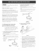
30" (76.2 cm) Min, Clearance Between the Top of the Cooking Platform and Unprotected Wood or Metal Cabinet A Min. 13" (33 cm) Max, Depth For Cabinet Installed Above Cooktop. t" Dimension J is the Minimum Distance Required Between Rear of Top Panel to Adjacent Surfaces. 18" Min. (45.7 cm) Dimension K is the Minimum Clearance Required From Left Side of Top Panel to Clearance Dimension H is the Minimum Clearance Required From Right Side of Top Panel to Adjacent Combustible Surface.
Important Notes to the Installer 1. Readallinstructions contained intheseinstallation instructions beforeinstalling thecooktop. 2. Remove allpackingmaterialbeforeconnecting tile electrical supplytothecooktop. 3. Observe allgoverning (;odes andordinances. 4. Besureto leavetheseinstructions withtheconsumer. Important Note to the Consumer • Adjust surface burner flame size so it does not extend beyond the edge of the cooking utensit. Excessive flame is hazardous.
Safety 1. WanNOut_et on the Cooktop Do not allow dry empty pans to heat on the cooktop as this could ruin the pan and cause a fire hazard. Do not use a wok on the cooking surface if it is equipped with a round metal support placed over the burner grate. This support acts as a heat trap which may damage the burner grate, drip bowls and burner head. It may also cause the burner to work improperly and create a carbon monoxide hazard. When lowering the cooktop be careful not to pinch your fingers.
3. Provide an Adequate Gas Supply The cooktop covered in these installation instructions is designed to operate on natural gas at 4" (10.2 cm) of manifold pressure or on LP gas at 10" (25.4 cm) of manifold pressure. A convertible pressure regulator is supplied with each surface unit and MUST BE CONNECTED IN SERIES between the supply line and the valve manifold regardless of which type of gas is being used.
Donot useflameto checkfor leaksfrom gasconnections.Checking for leakswith a flamemay resultina fireor explosion. Tightenall connectionsif necessary to preventgas leakagein thecooktopor supplyline. Checkalignmentof controlknobvalvesafter connecting the cooktopto thegassupplyto besurethe cooktopmanifoldpipehasnot moved.A misalignment couldcausethe valvestemsto rubontile controlpanel, resultingin a gasleakat tile valve. 2.Convertthe PressureRegulatorfrom LPGasto NATURAL Gas(seefigure 7) A.
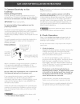
Pini X _/-- Hood A NaturalGas-_ Gas 2. Too Much Air (figure 12) If the air shutter is adjusted so that too much air flows into the burner, the flame will appear unsteady, will possibly not burn all the way around, and will be noisy (like a blowtorch). Z Hood nut Figure 9 5. Adjustments A. Burner Air Shutter Adjustment The air shutter adjustment for each of the four burners is located at the open end of the venturi tube on the valve hood. Tile shutter is held in place by friction fit. Figure 12 3.
7° Connect Emectricity Note: All hookups and adjustment shall be performed by qualified technicians. to Gas Cooktop Electrical Requirements 120 volt, 60 Hertz, properly grounded branch circuit protected by a 15 amp circuit breaker or time delay fuse. Do not use an extension cord with these cooktops. IMPORTANT Please read carefully. For persona! safety, properly grounded.
. Adjust the "LO" or "SIMMER" Setting of Surface Burner Valves (see Figure 15} Push in and turn each control knob to the "LO" (or "SIMMER") setting. The"LO" setting of each burner has been set at the factory to the lowest setting available to provide reliable reignition of the burner. If it does not stay lit on the"LO" setting, check the setting as follows. _Be this operation. A. B. extremely careful when performing Allow cooktop to cool to room temperature.
Notes 10
LA INSTALAaON Y EL SERVlaO DEBEN SER REAUZADOS POR UN INSTALADOR CAUHCADO° IMPORTANTE: GUARDE ESTAS INSTRUCaONES PARA USO DEL INSPECTOR ELECTR_CO LOCAL. LEA Y GUARDE ESTAS INSTRUCaONES PARA FUTURAS REFERENaAS __ Si todas [as instrucdones de 6ste manual no son observadas a [a [etra, se puede ocurrir incendios o exp[osiones que pueden causar da_os materiales, [esiones o [a muerte. PARA SU SEGURIDAD: -- No almacene o uti[ice gasotina u otros vapores y [iquidos inflamables artefacto.
Max. profundidad de gabinetes instalados por encima de la plancha de empotar es 13" (33 cm). 30" (76.2 cm) Minimo entre la parte superior de la plataforma de la plan(ha de cocinar y el fondo de una madera non protegida o armario metalico. ..... A Min. _] Dimensiones J este minimo distancia entre el borde posterior del hueco y lamas cerca superficie combustible pot encima del mostrador. Espacio Dimensiones K este espacio minimo desde el lado izquierdo de 24" (61 cm) almacenamiento de combustible.
Notas importantes No utilice jam_s su p[ancha de cocinar como calefactor. Elusoprolongadodelacocinasinla ventilaci6n adecuada puede set peligroso. • No guarde o haga uso de gasolina o otros vaporos y t[quidos infJamabIes acerca de est_ o cua[quieraparato. Sepuederesultaren incendioso explosi6nes. para el instalador 1. Lea todas los instrucciones de instalacion antes de realizar la instalacion de la plancha de cocinar. 2.
Medidas de seguridad p[ancha de codnar 1. Area para e[ uso de [a 1 0.5 cm)-* ; m 10" (25.4 cm) I Area recomen ' la toma de corriente a I tierra de 120V en el NOTA: Si no existe una toma de corriente, contacte a un electricista calificado para realizar la instalaci6n. : Pot favor lea antes de con la instalacion El aparato y su vdvula de apagado deben ser desconectados del sistema de suministro de gas durante cualquier prueba de presion del sistema a una presion de prueba en exceso de 1/2 psig.
3. Provea un adecuado suministro de gas VaHvuHa de derre manual Las planchas de cocinar abarcadas en estas instrucciones de instalacion estan diser-ladas para funcionar con gas natural de 4" (10.2 cm) de m(dtiple de admision o (;on gas propano de 10" (25.4 cm) de mL]ltiple de admision. Ablerto, Uni6n Uni6n t ReguHator de presi6n t (on) k.
Noutilicellamalibreparaverificarla existencia defugas.Laverificaci6n delasfugasconuna llamapuedeprovocarfuegoo explosi6n. Ajustetodastasconexionesencasoquesea necesario, paraevitarfugasdegasenla planchade cocinaro eneltubodesumininistro degas. Verifiquetaalineaci6ndetasvStvulasluegode conectarlaplanchadecocinaralsuministrodegaspara asegurar queno sehamovidolavalvuladelm01tiple. Unamalaalineaci6n puedeinducirlafriegadeltronco deperillade lavalvulasobreel paneldecontrol,y ocurrirenfugasenlavalvula.
Pasador -N _ 2. Demasiado Aire (figura 12) Si el obturador de aire esta dejando pasar demasiado aire al quemador, la llama sera inestable, posiblemente no habra llama a todo el rededor del quemador, y esta sera ruidosa (como un soplete). Capucha GasNatural-_ LP Figura9 6. Ajustes A. Ajustes de obturador de aire del quemador.
Seaconseja al consumidor queunelectricista calificado verifiqueel enchufede paredy el circuitoparaasegurar queelenchufeesteconectado a tierracorrectamente. IVl_todo Preferido f -" 8. Verifique la operad6n Refiera el Manual del usuario que viene (on la plancha de cocinar para las instrucciones de funcionamiento y el mantenimiento y la limpieza de su plancha de cocinar. No toquealosquemadores. Puedenestar suficientemente calientes par causar quemaduras. Enchure 1.
lncorrectas ajustas de instatad6n, modificati6nes y reparad6nes pueden causar quemaduras o da_os a Ja propiedad. ConsuJte est_ manuaJ. Para asistenda y m_s informad6n, consuJte un instaJador calificado, una agenda, Ja fabricante (distribuidor) o et suministrador de gas. agujerodela _.__ Paraese, apoyarse o sentarse en las puertas o caiones de esta estufa puede causar serias tesiones personates y tambi_n puede da_ar ta estufa.
TOP BURNER IGNITER OPTIONAL QUEMABOR BE ENCERDIDO SUPERIOR OPCIONAL BOUGIE O'ALLUMAOE-BRULEOR FACULTATIP_--- E E CAUTION_ I l I i TOP BURNER IGNITER OPTIONAL QUEMABOR DE ENCENmDO SUPERIOR OPCIONAL BOOGIE O'ALIOMAOE-BRULEUR I FACULTATIF-- ' IF--- {* E Et AVISO: ETIQUETE REALIZAR 4} _ LEF REAR iON BW i! TODOS LOS ALAMBRES ANTES DE DESCONECTAR ET MANTENIMIENTO DE LOS CONTROLESERROR 'I i TOP BURNER IGNITER QUEMADOR BE ENCENDIDO SUPERIOR BOOGIE D'ALLOMAOE-BRULEUR CAUSAR UN FUNCIONAMIENTO SI EL