Installation Instructions 30" Built-In Wall Oven 911.47712,47714,47719,47752,47754,47759, 49042,49043,49044,49049,49052,49053, 49054,49059 I If you have questions, contact our website at: www.sears.com • Proper installation is the responsibility of the installer and product failure due to improper installation is NOT covered under the warranty. Before You Begin Read these instructions carefully and completely. • IM PO RTANT-save instructions these for local inspector's • NOTE--This grounded. use.
Installation Instructions IMPORTANT SAFETY INSTRUCTIONS Electrical Requirements For Your Safety • Be sure your oven is installed properly by a qualified installer or service technician. This appliance must be supplied with the proper voltage and frequency, and connected to an individual, properly grounded branch circuit, protected by a circuit breaker or fuse having amperage as noted on rating plate. (Rating Plate is located on oven frame.
Installation Instructions Pre-lnstallation Checklist ALL INSTALLATION INFORMATION ON THE FOLLOWING PAGES IS TO BE USED FOR SINGLE AND DOUBLE OVEN INSTALLATION! Door removal is not a requirement for installation of the product, but is an added convenience. To remove the door: Open the oven door as far as it will go. Remove packaging materials. Check behind hinges and under false bottom.
Installation Instructions [_ Pre-lnstallation Checklist cont. d Remove the bottom trim from the top of the oven. It will be installed at the end of the installation process. The trim is wrapped separately and taped to the top of the unit. Place the oven on a table or platform even with the cutout opening. (Platform must support 150 Ibs. single, 275 Ibs. double.
Installation Instructions I-A-11 Cutout for Single Built-In Oven Cutout Cabinet Width 28 1/2" Min. I I I Allow 11/16" for overlap of oven over side edges of cutout Between inside Walls Must Be At Least 28 1/2- Wide Height 27 1/4" Min. i 27 5/16" Max,_ Junction Box 22" to Bottom of Junction Box Width Recommended Minimum Cutout Location from Floor 32 1/2" Cutout Depth 23 1/2" Min. Cutout Width 28 1/2" Min. 28 5/8" Max. Cutout Height 27 1/4" Min. 27 5/16" Max.
Installation Instructions Cutout for Double Built-In Oven Cutout Width 28 l/2"Min, <--28 518" Max. -'_ Cabinet _ Allow 11/16" for overlap of oven over aide edgea of cutout Allow a minimum of 21" for clearance to adjacent Allow 1" minimum for overlap of oven top and 1V¢' for bottom of cutout Box 30" Recommended Minimum Cutout Location from Floor 12" Cutout Depth 23 1/2" Min. Cutout Width 28 1/2" Min. 28 5/8" Max.
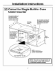
Installation Instructions I_ Cutout for Single Built-In Oven Under Counter Gas or electric cooktops may be installed over this oven. See cooktop installation instructions for cutout size. See label on top of oven for approved cooktop models. Gas and electrical connections for 30" gas cooktop must be located in an adjacent accessible location to the right. For 36" gas cooktop, the connections may be made to the left. 240V / 208V Junction Box Location Top and/or side fillers may between existing cabinets.
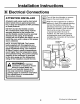
Installation Instructions I-B-] Electrical Connections ATTENTION Turn off the circuit breaker or remove fuses to the oven branch circuit. INSTALLER All electric wall ovens must be hard wired (direct wired) into an approved junction box. A plug and receptacle is NOT permitted on these products. With the oven supported on a table or platform in front of the cabinet opening, connect the flexible conduit to the electrical junction box as shown below.
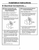
Installation Instructions I-B-] Electrical Connections Three-Conductor Branch Circuit Connection New Construction and Four Conductor Branch Circuit Connection • When installing in new construction, • When installing in a mobile home, or • When installing in a recreational When connecting to a three-conductor circuit, if local codes permit: or vehicle, cont. branch a.
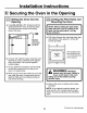
Installation Instructions Securing the Oven in the Opening Sliding the Oven Into the Opening I-_ a. Loop (do not tie) a 36" string around the conduit before the oven is slid into place. This will keep the conduit from falling behind the oven. BB Drilling the Pilot Holes and Mounting the Oven NOTE: Before drilling the pilot holes, make sure the oven is pushed as far back into the opening as it will go and centered. a.
Installation Instructions I-_ Preparing for the Bottom Trim Installation I-_ a. With oven installed, take the bottom trim and center it on the bottom front edge of the cabinet opening. b. Using the trim as a template, mark the center of each slot (two total) where the mounting holes will be drilled. a. Make sure flat side is up on the plastic bottom trim. b. Find the key slot on the back of the trim. With Lower Trim in Position, Mark (2) Mounting Hole Locations c. Remove the trim. d.
Installation Instructions Replacing the Oven Door NOTE: The oven door is heavy, You may need help lifting the door high enough to slide it into the hinge slots, Do not lift the door by the handle, I-_ Open the oven door as far as it will open. ['_ Push the hinge locks up against the front frame of the oven cavity, to the locked position. Hinge in Locked Position [_Liftthe oven door by placing one hand on each side. The door is heavy, so you may need help. Do not lift the door by the handle.
Installation Instructions Pre-Test Checklist Remove all protective and any stickers. film, if present, Check to be sure that all wiring is secure and not pinched or in contact with moving parts. [_ Check thepage bottom properly that (see 11).trim is installed [_ Check to be sure the mounting screws are installed and flush with the side trim (see page 10). Operation Checklist Remove all items from the inside of the oven.
NOTES 14
Instrucciones de instalacibn I &Preguntas? Horno de pared empotrado de 30" 911.47712,47714,47719,47752,47754,47759, 49042,49043,49044,49049,49052,49053, 49054,49059 I Visite nuestro sitio en la Web: www.sears.com • La instalacibn apropiada es responsabilidad del instalador y la falla del producto pot una instalacibn incorrecta NO estd cubierta por la garantfa. Antes de empezar Lea estas instrucciones cuidadosa y completamente. • IMPORTANTE-Guarde instrucciones y tdngalas para el inspector local.
Instrucciones de instalacibn INSTRUCCIONES IMPORTANTES Para su DE SEGURIDAD uridad Requisitos eldctricos • Cerci6rese de que su horno sea instalado adecuadamente por un instalador calificado o por un t6cnico de servicio. Este aparato debe ser abastecido con et voltaje y la frecuencia adecuados, y conectado a un circuito ramal individual que se encuentre conectado a tierra apropiadamente.
Instrucciones de instalacibn Lista de control antes de la instalacibn iTODA LA INFORMACION PARA LA INSTALACION EN LAS PAGINAS SIGUIENTES ES PARA SER USADA EN LA INSTALACION DE HORNOS DE UNA O DOS UNIDADES! No es necesario retirar la puerta para la instalaci6n del producto, pero hacerlo facilita la instalaci6n. Para retirar la puerta: Abra la puerta Retire los materiales de embalaje. Revise detr&s de las bisagras y debajo del fondo falso.
Instrucciones de instalacibn [_ Lista de control antes de la instalacibn cont. Extraiga la moldura de fondo de la parte superior del homo. La misma ser_. instalada al final de la instalaci6n. La moldura de fondo est,. envuelta por separado y pegada a la parte superior de la unidad. Coloque horno mesa odel plataforma el al nivel sobre de la la abertura corte. (La plataforma debe soportar 150 libras para hornos de una unidad y 275 libras para hornos de dos unidades.
Instrucciones de instalacibn Corte para el horno de una unidad Ancho del corte Ubicacibn de la caja de conexi6n Permita 11116" de sobrepaso del homo sobre los bordes laterales del corte 22" hasta el fondo de la caja de conexidn 21 Permita un mlmmo de 1" para el Ubicacibn minima recomendada para el corte desde el Ancho del gabinete 30" Ubicacibn minima recomendada para el corte desde el piso 32 112" Profundidad del corte 23 112" Min. Ancho del corte 28 112" Min. 28 518" Mdx.
Instrucciones de instalacibn Corte para el horno de dos unidades Ancho del Ancho del gabinete <_28 1/2" Urn. 28 518" M_x. --_" gabinete _,. 5". Ubicacibn de la caja de conexi6n / Permita 11116" para sobrepaso del horno sobre los bordes laterales del corte --_. Permita un minimo de 21" de espacio para las esquinas, cajones, paredes, etc.
Instrucciones de instalacibn Corte para el horno de una unidaddebaio de la superficie del gabinete Las estufas eldctricas o de gas se pueden instalar sobre este horno. Consulte las instrucciones de la estufa para el tama_o del corte. Consulte la etiqueta encima del homo para los modelos de estufas aprobados. Las conexiones para una estufa estar ubicadas de facil acceso Ubicaci6n de la caja de conexi6n 240V/208V de gas y eldctricas a gas de 30, deben en un lugar adyacente en el lado derecho.
Instrucciones de instalacibn Conexiones eldctricas ATENCION AL INSTALADOR: Desconecte el interrupter del circuito o retire los fusibles que alimentan el circuito ramal del horno. Con el horno enfrente de la abertura del gabinete, sobre una mesa o plataforma conecte el conducto flexible a la caja de conexiSn como se muestra en la figura. Usted necesitar_, comprar una abrazadera liberadora de presi6n para completar la conexi6n del conducto hacia la caja de conexi6n.
Instrucciones de instalacibn Conexiones eldctricas cont. Conexi6n de circuito ramal de tres conductores Conexi6n para nueva . construccion y de circuito ramal de cuatro conductores Cuando conecte un circuito ramal de 3 conductores, si los c6digos locales Io permiten: • Cuando se instale en una construcci6n nueva, o a. Conecte el alambre descubierto del horno con el alambre neutro (blanco) del circuito ramal (blanco o gris), usando una tuerca para alambres.
Instrucciones de instalacibn Posicibn firme del horno en la abertura Cbmo deslizar el horno en el interior de la abertura Cbmo taladrar los orificios piloto y montar el horno a. Coloque (sin atar) una cuerda de 36" alrededor del conductor antes de deslizar el homo en su lugar. Esto evitar_ que el conducto se caiga detrAs del homo. I _< NOTA: Antes de perforar los orificios piloto, cercibrese de que el horno se empujb hasta el fondo y de que este centrado. a.
Instrucciones de instalacibn r_ Preparacibn para la instalaci6n de la moldura de fondo I-€--_ cbmo instalar la moldura de fondo pldstica a. Con el horno instalado, tome la moldura de fondo y centrela en el borde frontal del fondo de la abertura del gabinete. b. Usando la moldura como una plantilla marque el centro de cada ranura (dos en total) donde los orificios de montaje ser&n taladrados. a. Aseg_rese de que el lado piano est6 hacia arriba de la moldura de fondo pl&stica. b.
Instrucciones de instalacibn I-D-1 Cbmo instalar la puerta del horno r-_ NOTA: La puerta del horno es pesada. Quizds necesite ayuda para levantar y deslizar la puerta hacia abajo sobre las bisagras. No levante la puerta por la empu_adura. Abra la puerta del homo hasta el maxlmo. ['0--"_ Empuje topesdedela las bisagras el marco los frontal cavidad del contra homo, hasta alcanzar la posici6n de cierre. Bisagra en la posici6n de cierre ['_ Levante la puerta una del horno colocando mano en cada lado.
Instrucciones de instalacibn Lista de control antes de la prueba Retire cualquier cinta este de protecci6n etiqueta que todavia presente. [_ Inspeccione la moldura de fondo para cerciorarse de que est& instalada apropiadamente (ver p&gina 11 ). y los alambres est_n bien conectados y Revise para asegurarse de que todos no aplastados o en contacto con partes m6viles.
NOTAS 14