Use & Care Guide Model No. 153.332620 40 Gallon Tall 153.332640 50 Gallon Tall LLC I
Your safety and the safety of others is extremely Many safety-related messages and instructions important in the installation, have been provided use and servicing in this manual of this water heater. and on your own water heater to warn you and others of It is very important that the meaning n a potential injury hazard. Read and obey all safety messages and instructions throughout this manual. of each safety message is understood by you and others who install, use or service this water heater.
Read and understand instruction Fire Hazard manual and safety messages before installing, operating or servicing this water heater. Failure to follow instructions and safety messages could result in For continued protection against riskof fire: • Do not install water heater on carpeted floor. death or serious injury. Instruction manual must remain with water heater. • Do not operate water heater if flood damaged.
SAFE INSTALLATION, USE AND SERVICE ................................................................................................. Important Definitions ................................................................................................................................................. SAFETY PRECAUTIONS ........................................................................................................................... Table of Contents ............................................
ELECTRICAL............................................................................................................................................... 24 ElectricalConnections ...................................................................................................................................... 24 SolarInstallation .............................................................................................................................................. 24 WiringDiagram .................
12 - YEAR LIMITED WARRANTY ON WATER HEATER For twelve years from the date of purchase, if this water heater is installed and operated in a single-family owner's manual instructions and all local applicable plumbing codes, Sears will: . • home in accordance with the Supply free water heater parts for those that are defective in material or workmanship• Supply a free water heater for one that develops a leak.
Thank Youforpurchasing aKenmore water heater. Properly installed andmaintained, itshould giveyouyears oftrouble freeservice. If youshould decide thatyouwantthenew water heater professionally installed bySears call1-800-4-MY-HOME ®.Theywillarrange for prompt, quality installation bySears authorized contractors. Massachusetts Code requires this water heater to be installed accordance with Massachusetts Code and 248-CMR 5.00. Complies California in 248-CMR 2.
MODEL NUMBER TANK CAPACITY IN GALS (LTRS) TYPE INPUT RECOVERY OF RATE RATE GALS. GAS (Btu/hr) PER HOUR @ 90°F RISE MINIMUM VENT PIPE DIA. INCHES DIAMETER HEIGHT TO INCHES JACKET TOP (mm) INCHES (mm) (mm) 153.332620 40 (151) Natural 40,000 42.6 3 (76)or4(102) 20 (508) 58 (1473) 153.332640 50 (189) Natural 40,000 42.6 3(76)or4(102) 22 (559) 57.
MATERIALS NEEDED To simplify the installation Sears has available the installation parts shown below. You may or may not need all of these materials, depending on your type of installation. METAL DRAIN PANS AVAILABLE EXPANSION TANKS FOR THERMAL EXPANSION CONDITIONS AVAILABLE IN 2 GALLONS (7.6 LITERS) AND 5 GALLONS (18.9 LITERS) CAPACITY THROUGH LOCAL SEARS STORE OR SERVICE CENTER.
GET TO KNOW YOUR A B C D E F G H I J K L M N O P Q R S T Vent Pipe Draft hood Anode (Not Shown) Hot Water Outlet Insulation Gas Supply Piping Manual Gas Shut-off Valve Ground Joint Union Drip Leg (Sediment Trap) Inner Door * INSTALL IN ACCORDANCE WITH LOCAL CODES.
This gas water heater was manufactured to voluntary safety standards to reduce the likelihood of a flammable vapor ignition incident. The new technology used in meeting these standards makes this product more sensitive to installation errors. Please review the following checklist and make any required installation upgrades or changes. Questions? Installation Contact Sears at (1-800-469-4663).
Removing the Old Water Heater ® ® ® Q ® Attach a hose to the water heater drain valve and put the other end in a floor drain or outdoors. (See Figures 2 and 5.) Open the water heater drain valve. MANUALGAS JOINT UNION PIPE (DO NOT CAP OR PLUG) CHECK WITH LOCAL UTILITY FOR MINIMUM HEIGHT FIGURE ® 6" MAXIMUM f AIR GAP SUITABLE DRAIN -_f ® FIGURE Q 5. Disconnect the vent pipe from the draft hood where it connects to the water heater.
Location If flammable liquids or vapors have spilled or leaked in the area of the water heater, leave the area immediately and call the fire department from a neighbor's home. Do not attempt to clean the spill until all ignition sources have been extinguished. Requirements Carbon Monoxide Poisoning Hazard Do not install in a mobile home. Fire or Explosion Do ng so can resu t n carbon monox de po son ng and death. Hazard • Read instruction manual before installing, using or servicing water heater.
Pmpe_y Damage Hazard • AJJwater heaters eventually Jeak EXHAUST FAN • Do not install without adequate drainage, / IMPORTANT: The water heater should be located in an area where leakage of the tank or connections wilt not result in damage to the area adjacent to the water heater or to lower floors of the structure. Due to the normal corrosive action of water, the tank wilt eventually leak after an extended period of time.
Explosion Hazard • Use a new CSA approved gas supply line. • Install a shut-off valve. • Do not connect a natural gas water heater to an L.P. gas supply. • Do not connect an L.P. gas water heater to a natural gas supply. • Failure to follow these instructions can result in death, explosion, or carbon monoxide poisoning. FIGURE 12. Gas Pressure Gas Requirements IMPORTANT: Read the rating plate to be sure the water heater is made for the type of gas you wilt be using in your home.
Gas Pipe Capacity Table Explosion Hazard Explosion Hazard • Use a new CSA approved gas supply line. • Gas leaks can not always be detected by smell. • Install a shut-off valve. • • Do not connect a natural gas water heater to an L.P. gas supply. Gas suppliers recommend that you use a gas detector approved by UL or CSA. • For more information, contact your gas supplier. • If a gas leak is detected, follow the "What to do if you smell gas" instructions on the cover of this manual.
TABLE 3 Carbon Monoxide BTUH Input Warning Minimum Square Feet with Typical Room with 8' Ceiling 8' Ceiling Water heater must be vented to outdoors. Vent must be installed by a qualified technician using the installation instructions. 30,000 188 9x21 45,000 281 14 x20 Examples of a qualified technican include: gas technicians, authorized gas company personel, and authorized service persons.
free area of the opening to which they connect. The minimum dimension of rectangular air ducts cannot be less than three inches. The size of each of the two openings is determined by the method in which the air is to be provided. Refer to Table 4 to calculate the minimum free area for each opening. Figures 15, 16, 17 and 18 are typical examples of each method.
Gable Vent Alternative ,/too t%a,, Opening------..__...._] Location ,_' 'nsulation Confined Space \ Conflne I.. lii Space 1 sq. in. per 3000 BTUH \Outlet Air to the Attic 1 sq. in. per 4000 BTUH Inlet Air from the Alternative Crawl Air inlet Space I All Air From Outdoors 1 sq. in. per 4000 BTUH All Air From / Outdoors: Crawl Space/Outlet Open Foundation___ Vent FIGURE FIGURE Attic This water heater uses remove exhaust gases for combustion is taken or is ducted in from the Ventilation").
40 Gal. Water Heater: Align the reducer flue over top of baffle as shown in Figure 19 (NOTE: reducer flue must be installed on 40 gal. water heater above elevation 5,400 Ft. (1,646 m) from sea level). Z223.1(NFPA 54)-current edition. • The connector must be installed above the extreme bottom of the chimney to prevent potentially blocking the flue gases. • The connector must be firmly attached and sealed to prevent it from falling out. 40 & 50 Gal.
2 FT. Minimum Above IJ_L _ Any Object Within 3 FT. Minimum Piping Installation rizontally Support Strap_ _ , _Type Maintain L Clearance* f i1_---_'_ Piping, fittings, and valves should be installed according to the installation drawing (Figure 23). If the indoor installation area is subject to freezing temperatures, the water piping must be protected by insulation. B Double ........... Wall Vent Pipe \ **Maintain [] _1 Vent Connector The water supply pressure should not exceed 80 psi.
In a closed system ,/thermal _r expansion Cold Water inlet Valve Closed System/Thermal use a Expansion tank I]Pressure Reducing HValve with Bypass Hot Water,.._ Outlet =:_ [_ _Cold H_H Water Supply/_ to Fixture SupplyMain_Water Pmpe_y Damage Hazard • All water heaters eventually leak • Do notinstallwithoutadequate As water is heated, it expands (thermal expansion). In a closed system, the volume of water will grow.
For protection against excessive pressures and temperatures, a temperature and pressure relief valve must be installed in the opening marked "T & P RELIEF VALVE" (see Figure 25). This valve must be design certified by a nationally recognized testing laboratory that maintains periodic inspection of the production of listed equipment or materials as meeting the requirements for Relief Valves for Hot Water Supply Systems, ANSI Z21.22.
Electrical Connections IMPORTANT: Do not use an extension cord to connect the water heater to an electrical outlet. Before plugging in the water heater, always make sure: • The water heater and the outlet are properly grounded. • The Voltage and frequency correspond to that specified on the water heater. • • The electrical outlet has the proper overload fuse or breaker protection.
Operating Instructions Read and understand these directions thoroughly before attempting to operate the water heater. Make sure the view port is not missing or damaged (See Figure 36). Make sure the tank is completely filled with water before operating the water heater. The gas control valve/thermostat has a "On/Off Switch" and needs to be turned on before water heater is operational. Check the label on the front of heater near the gas control valve/ thermostat for the correct gas.
Water Heater Operation Checking the Draft Figure 29 below shows the water heater's sequence of operation when a call for heat is initiated. The ignition control module wilt attempt to light the burner three times. If the ignition control does not detect ignition it wilt enter lockout mode, indicated by display flashing status code (see status code 3 page 38 and/or status code 8 page 39). Burn Hazard Do not touch vent. Doing so can result in burns.
Burner Flames should be used at the hot water taps used by these people or at the water heater. Mixing valves are available at plumbing supply or hardware stores, see Figure 24. Follow manufacturer's instructions for installation of the valves. Before changing the factory setting on the thermostat see Table 5 and Figure 32. Using the lowest hot water temperature that meets your needs will also provide the most energy efficient operation of the water heater.
may satisfy your normal hot water needs. If hot water use is expected to be more than normal, a higher thermostat setting may 3. Disconnect the electric connection by unplugging the water heater from the wall outlet. be required to meet the increased demand. When leaving your home for extended periods (vacations, etc.) Set the electronic control display temperature "COOLER"(_)button to its lowest setting.
Draining and Flushing V! I mT:Wlet =1 Temperature • Hotwater discharge and Pressure burn hazard. • Keep clear of relief valve discharge unit. • Temperature available. • Read limiting instruction temperature Relief Valve valves manual Explosion Harzard are Temperature-pressure relief valve must comply with ANSI Z21.22-CSA 4.4 and ASME code. for safe setting.
Replacement Removing the Burner Burner Assembly Parts IMPORTANT: The following maintenance procedures are for the FVIR System components and should be performed by a qualified technician. the Manifold/Burner Manifold/ 1. Take off the burner by removing the two (2) screws located underneath the burner. 2. Check the burner to see if it is dirty or clogged. The burner may be cleaned with soap and hot water (Figure 36).
6. Reposition the manifold component block in the mani-fold door opening and secure it with the retainer clip. 7. See Replacing the Manifold/Burner Replacing Assembly Assembly. External Inspection & Cleaning Air Intake Chamber Screen of the At least twice annually inspect the air intake chamber screen (Figure 38) for any dust or debris that may have accumulated on the louvers.
10. Replace the outer door (see item K page 10). Door Gasket 3. Burner i Viewport 2. Slot 4. Fill the tank completely with water. NOTE: To purge the lines of any excess air, keep the hot water faucet open for 3 minutes after a constant flow of water is obtained. 5. Turn on the gas supply and test the gas supply connections by brushing on an approved noncorrosive leak detection solution. IMPORTANT: Do Not splash solution onto the electrical connections. Bubbles forming indicate a leak.
Start Up Conditions Thermal NOTE: Expansion tanks are pre-charged with a 40 psi air charge. If the inlet water pressure is higher than 40 psi, the expansion tank's air pressure must be adjusted to match that pressure, but must not be higher than 80 psi. Expansion Property Damage Hazard HOT COLD/ WATER HEATER COLD WATER (3) PRESSURE INLET FITTING VALVE WITH REDUCING BY-PASS • Avoid water heater damage. r....--w.-. _- -...._ • Install thermal expansion tank or device if necessary.
Condensation Operational Whenever the water heater is filled with cold water, some condensate will form while the burner is on. A water heater may appear to be leaking when in fact the water is condensation. This usually happens when: • A new water heater is filled with cold water for the first time. • Burning gas produces water vapor In water heaters, particularly high efficiency models where flue temperatures are lower.
Leakage Checkpoints B, *Condensation may be seen on pipes in humid weather or pipe connections may be leaking. C, *The anode rod fitting may be leaking. D. Small amounts of water from temperature-pressure relief valve may be due to thermal expansion or high water pressure in your area. E, *The temperature-pressure the tank fitting. F, Water from a drain valve may be due to the valve being slightly opened. G, *The drain valve may be leaking at the tank fitting. H.
Pressurized Operational 1. 2. 3. 4. Combustion Chamber System Checklist Manifold gasket properly sealed. Viewport not damaged or cracked. Combustion chamber free of debris and undamaged. Manifold component block properly installed. PROBLEM NO HOT WATER INSUFFICIENT HOT WATER SLOW HOT WATER RECOVERY WATER TOO HOT 5. 6. No leaks at manifold connection. Manifold door screws securely tightened. CORRECTIVE POSSIBLE CAUSE(S) 1. 2. 3. 4. 5. 6. Transformer unplugged. No power at outlet.
continued: CORRECTIVE ACTION PROBLEM POSSIBLE CAUSE(S) 1. Tighten threaded connections. WATER LEAKS 1. Improperly sealed, hot or cold supply connections, relief valve, drain valve or thermostat threads. 2, Leakage from other appliances or water lines. 3. Condensation of flue products. 2. Inspect other appliances near water heater. 3. See "START UP CONDITIONS", 4. Excessive water pressure. 4. Use a pressure reducing valve and relief valve. 5. 6. Heater stacking. Closed water system. 5. 6.
POWER IGN VA¢ LOCK HEATING CHECK FV-SENSE E¢O P-ANODE P-SW LDO_W OPEN CLEAN 8CI_EH THMSTR SHORT b ELECTRONIC CONTROL DISPLAY Please check guidelines below. For your safety, water heater service should be performed only by a qualified Read the GENERAL SAFETY INFORMATION supplied by the water heater manufacturer. CONTROL DISPLAY STATUS PROBLEM service person. SOLUTION 1.
CONTROL DISPLAY STATUS 6. "P-SW", "OPEN", and "CLEAN SCREEN" Flashing PROBLEM SOLUTION The air pressure switch contacts remain open longer than 1 1 seconds after the combustion fan is energized. 1. Clean the screen on the combustion air intake chamber. Turn the power "OFF" for 10 to 20 seconds then "ON" again to clear the error code. If the problem persists: 2, Ensure the pressure switch sensing tube is in good condition and securely connected at both ends. 3.
CONTROL DISPLAY STATUS 9. 11. from previous SOLUTION 4. "FV-SENSE" Flashing (Continued 10. PROBLEM page) "LDO-SW", "OPEN", and "CLEAN SCREEN" Flashing "FV-SENSE" and "OPEN" Flashing The air pressure switch contacts remain open longer than 5 seconds after the combustion fan is energized. Flammable Vapor Sensor is open System must be manually reset by entering a special FVS reset sequence into the Electronic Control Display.
AUTOMATIC RESET TIME DELAY 3 MINUTE I I A SWITCH TO OPEN NUMBER DISPLAY 7 ERROR YES AUTOMATIC RESTART TIME DELAY ONE HOUR NUMBER 8 COMBUSTION AFTER ' I I GAS VALVE ...... FAN TINO .... I OFF _SE I wAI_F;L_YTP_s°_ENUMBER 6 NO N_ _NO .............. .......... TURN ERROR OFF DISPLAY YES ._YES I l , CTNR{_N:_ _ / I............... I ........
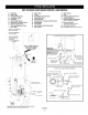
KENMORE ® ELITE HIGH EFFICIENCY PCC (Pressurized Combustion Chamber) NATURAL GAS WATER HEATERS 153.332620 40 Gallon Tall (Natural) 153.332640 50 Gallon Tall (Natural) _ _3_¸ _7, Key No. Parts Description 153.332620 153.
Your Home For troubleshooting, product manuals and expert advice: managemylife www.managemylife.com For repair - in your home - of all major brand appliances, lawn and garden equipment, or heating and cooling systems, no matter who made it, no matter who sold it! For the replacement parts, accessories and owner's manuals that you need to do-it-yourself. For Sears professional installation of home appliances and items like garage door openers and water heaters.