GAS-FIRED, DIRECT VENT, CONDENSING, HOT WATER BOILERS INSTALLATION INSTRUCTIONS These instructions must be aff'Lxedon or adjacent to the boiler WARNING Improper installation, adjustment, alteration, service, or maintenance can cause injury or property damage. Refer to this manual. For assistance or additional information consult a qualified installer, service agency, or the gas supplier. Sears, Roebuck and Co. Hoffman Estates, IL 60179 U.S.A.
TABLE OF CONTENTS INTRODUCTION BOILER RULES RATINGS AND CAPACITIES FOR SAFE INSTALLATION BEFORE A. ................................................................................................... INSTALLING ....................................................................... AND OPERATION ................................................ THE BOILER ........................................................................ codes ...................................................................
I. circulator pump.................................................................................................. J. drain valve....................................................................................................... K. relief valve....................................................................................................... L. flame rollout safetyshutoff..................................................................................... M. (optional)externalcondensate pump......
The Kenmore(K90) is a gas-fireddirect vent hot waterboiler with castaluminumboiler sections. A revolutionary castaluminumheatexchangermeansbetterheattransferandthermalstoragethan similarly sizedcastiron boilers, which resultsin higher efficiency. The heatingsystemwaterabsorbs large amountsof heatfrom the castaluminumheatexchanger,coolingthe flue gasesandcausing condensation.
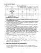
TABLE 1 SEA LEVEL RATINGS - NATURAL AND PROPANE GASES Model Input *(MBH) + + Heating Capacity *(MBH) K90-50 K90-75 K90-100 50 75 100 45 68 90 Net I =B =R Rating *(MBH) Shipping Weight (lbs.) Flue Dia. 39 59 78 220 220 220 2" CPVC & Pvc 2" CPVC & Pvc 2" cPVC & Pvc "1 MBH = 1,000 Btuh Btuh = British Thermal Units Per Hour These low pressure gas-fired hot water boilers are design certified by CSA International for use with natural and propane gases.
The conversionshall be carriedout by a manufacturer's authorized representative, in accordance with the requirements of the manufacturer, provincial or territorial authorities having jurisdiction, and in accordance with the requirements of the CAN/CGA-B149.1 and CAN/CGA-B149.2 Installation Codes. The certified field conversion kit includes a conversion data plate, indicating that the boiler has been converted for high altitude use.
TABLE 1C K90-75 NATURAL ELEVATION (FEET) NOMINAL INPUT (MBH) HEATING CAPACITY (MBH) NET I=B=R RATING (MBH) GAS ORIFICE DRILL SIZE MANIFOLD PRESSURE (INCHES WATER COLUMN) PRESSURE SWITCH SETPOINT (INCHES TABLE WATER 1D K90-75 PROPANE TABLE WATER 1E K90-100 NATURAL (INCHES WATER COLUMN) PRESSURE SWITCH SETPOINT (INCHES WATER TABLE 1F K90-100 1.35 1.35 1.35 7,500 56.5 50.9 44.1 .0760 2.3 8,500 52.0 46.8 40.6 .0760 2.1 1.35 1.35 1.35 1.35 GAS HIGH ALTITUDE RATINGS 0-2000 75.0 68.0 58.9 .
1. Read the entire installation manual before beginning the installation. Failure to follow these rules for safe installation and operation and these instructions could cause a malfunction of the boiler and result in death, serious bodily injury, and/or property damage. 2. Check all applicable state and local building codes and utility company requirements before installation. The installation must conform with these requirements in their entirety.
Whererequiredby the authorityhavingjurisdiction, the installationmustconformto the American Societyof MechanicalEngineersSafetyCodefor Controlsand SafetyDevicesfor Automatically Fired Boilers, No.CSD-1. The installation must conform to the requirements absence Installers of such requirements, - Teclmiciens B. BOILER to the National of the authority having jurisdiction or, in the Fuel Gas Code, ANSI Z223.1 - latest revision. Follow local regulations with respect to installation of CO (Carbon Detectors.
D. LOCATING THE BOILER TABLE 2 BOILER CLEARANCES L_IT COMBUSTIBLE ACCESSIBILITY/ CLEANING CONSTRUCTION 1" TOP LEFT SIDE RIGHT 0 and air intake 2. Accessibility clearances, which The boiler NOT 4. terminals back parts 8"at walls systems served and as close to the vent than required fire protection clearances may be achieved or partitions. for installation in Table be maintained in closets to access another that normally 2 indicate between of the boiler.
Combustion air and vent pipe connections must terminate together in the same atmospheric pressure zone, either through the roof or sidewall (roof termination preferred). See Fig.9 & 10 for required clearances.
G. FOUNDATION REQUIREMENTS Boiler must be placed on level surface. NOTE: Boiler is NOT to be installed on carpeting. 1. If boiler is not level condensate drain lines will not function properly. Adjustable feet are located on the boiler to make up for minor surface irregularities or tilt. 2. Wood frame or blocks may be used to raise boiler to maintain drain pitch or to be above external condensate pump reservoir. H.
NOTE: Refer to manual section "LOCATING and maintenance. THE BOILER" for required clearances for servicing CAUTION Copper supply and return piping must NOT be installed directly into aluminum boiler section castings due to galvanic corrosion between dissimilar metals. Iron or steel bushings or pipe nipples should be used between copper system piping and boiler to make final connection to boiler. Also, the use of dielectric unions is acceptable.
SUPPLY VALVE SERVICE -_ f TO SYSTEM RETURN CIRCULATOR FROM _J_'-SYSTEM --_ PURGE VALVE SERVICE VALVE FIGURE 2 SINGLE ZONE BOILER 13 PIPING (DRAIN)
f VALVE OI_E SERVICE VALVE SUPPL ZONES TO ZONE SERVICE VALVE CIRCULATOR FROM ZONES VALVES (DRAIN) ZONE SERVICE VALVE ZONE SERVICE VALVE FIGURE 3 MULTI ZONE BOILER 14 PIPING WITH ZONE VALVES
ZONE SERVICE VALVE VALVE FLOW CHECK TO ZONES --_ ZONE SERVICE VALVE CIRCULATORS FLOW CHECK VALVE ZONES PURGE VALVES VALVE FROM (DRAIN) SERVICE ZONE SERVICE VALVE NOTE: When zoning with circulators, the furnished circulator pump should be used as one of the zone pumps. Each stripped end of the electrical wires for the circulator pump inside the junction box should be taped or wire nutted to prevent short circuits. Unplug the circulator pump wiring at the integrated boiler control.
RELIEF VALVE DISCHARGE PIPING FIGURE B. PRESSURE RELIEF 5 RELIEF VALVE DISCHARGE PIPING VALVE The boiler is furnished with a factory installed relief valve in the top of the boiler. Provide ¾" piping from the supplied relief valve to a local floor drain, but leave an air gap between piping and drain. No shutoff of any description shall be placed between safety relief valve and the boiler, or on the discharge pipes between such safety valve and the atmosphere.
MANUAL FILL VALVE AIR BUSHING" TEE" _" COLD WATER -FILL NIPPLE (FURNISHED INSTALLED ON PACKAGED BOILER) 3/4" • - STREET FURNISHED IN PARTS BAG.
CLOSED TYPE E_°ANSION TANK L MANUAL VALVE COLD FILL _CHEUK AND REDUCING FIGURE 7 PRESSURE VALVE CONVENTIONAL(closed type) EXPANSION ]8 TANK PIPING
OPEN DRAIN PIPE TO BE PITCHED DOWN TO FLOOR DRAIN AT A MINIMUM I/4" PER FOOT TO DRAIN CONDENSATE DRAIN THREADED NIPPLE (INSTALLED) FIGURE D. CONDENSATE The condensate used. PVC TEE I/2"SMPxl/2"SMPxl/2 "NPT FURNISHED IN PARTSBAG 8 CONDENSATE DRAIN PIPING trap is built into the boiler, an external trap is not required Provide '/2"PVC condensate drain and fittings. at a minimum of ¼"per foot.
E. FILLING CONDENSATE ON THE INITIAL START TRAP WITH WATER UP THE CONDENSATE TRAP MUST BE MANUALLY FILLED WITH WATER The following are the steps required to initially fill the condensate trap for start up, these steps are only required at the initial start up or if maintenance requires draining of the condensate trap: 1. Disconnect 2. 3. Pour about 1 cup of cold tap water into the vent drain line with a proper funnel.
In Canada construct schedule-40 CPVC, all combustion air and vent pipes for this unit of CSA or ULC certified schedule-40 PVC, PVC-DWV or ABS-DWV pipe and pipe cement. SDR pipe is NOT approved in Canada. Combustion air and vent piping connections on boiler are sized for 2" pipe. Any pipe size change (to 3") must be made outside of the boiler casing in a vertical run of pipe to allow for proper drainage of vent condensate.
. Consideration for the following should be used when determining an appropriate location for termination of combustion air and vent piping: • Comply with all clearances required as stated in paragraph 7. • Termination should be positioned where vent vapors will not damage plants/shrubs or air conditioning equipment. • • • • • • . Termination should be positioned so that it will not be effected by wind eddy, air born leaves, snow, or recirculated flue gases.
FIGURE 10 SIDEWALL VENT/INTAKE 23 TERMINATIONS
2" (50,Smm) COMBUSTION INTAKE 2" (60,8nu,n } CPVC VENT/INTAKE _- TERMINATION8 AIR P_PING VENT PIPING (FURNISHED) 2" (60 8turn) CPVC COUPLING (FURNISHED 2" (60,gmm) OIAMETER VENT AND COMBUSTION AIR tNTAKE PIPING 15' (4.57m) MAXIMUM LENGTH TOTAL WITH 4 - D0" EU_OWS FOR Qg0.100 26' (6.t 0m) _M LENGTH TOTAL wm-I 4 - Go* ELBOWS FOR Og0.78 AND GgO. SO 2' (.8t m) M_NIMU_ LENGTH TOTAL WrTH 4 - gO"ELBOWS FOR ALL 1.52m (FU4RNISHED) 3" (76.2mm) COMBUSTION AIR INTAKE PIPING 2" {50.
B. INSTALLATION 1. Attach combustion air intake piping to supplied Fernco 2" coupling on mixer. Attach vent piping to furnished 2" CPVC vent tee on draft inducer outlet. NOTE: All pipe joints are to be water tight. 2. Working from the boiler to the outside, cut pipe to required length(s). 3. Deburr inside and outside of pipe. 4. Chamfer outside edge of pipe for better distribution of primer and cement. 5. Clean and dry all surfaces to be joined. 6. Check dry fit of pipe and mark insertion depth on pipe.
B. CONNECTING THE GAS PIPING Refer to Fig.12 for the general layout at the boiler. It shows the basic fittings you will need. The gas line enters the boiler from the right side jacket panel. The boiler may receive the gas supply pipe through the left side, or rear jacket panel by relocating the gas valve connector and pipe assembly. The boiler is equipped with a 1/2" NPT connection on the gas valve for supply piping. The following rules apply: 1.
The length of pipe or tubing should be measured regulator. from the gas meter or propane f//_GAS second stage SUPPLY PIPING SHUT-OFF VALVE TRAP GROUND UNION FIGURE 12 JOINT GAS PIPING WARNING TURN OFF ELECTRICAL POWER AT FUSE BOX BEFORE MAKING ANY LINE VOLTAGE CONNECTIONS. FOLLOW LOCAL ELECTRICAL CODES. All electrical work must conform to local codes as well as the National Electrical Code, ANSI/NFPA70, latest revision.
switch junction box and power supply connection points. Connect black (hot) lead from the power supply to either of the unused brass screws on the service switch. Connect the white (neutral) lead from the power supply to the white screw on the service switch. Connect the green (ground) lead from the power supply to the ground (green) screw on the service switch.
f MIRE COLOR CODE t20 VOLT CIRCULATOR BK = BLACK W = WHITB G = GREEN Y = YELLON Y 24 VOLT _3.....__ THERMOSTAT _ NEUYRAL'-_ BOILER HOT _-120 VOLTS IN J-BOX S'I_'VX_ SNITU_ J C.
llil r_ll __ _ _' i' H .... N _uO T_ U_T OI = gL_¢k : YELLOW _UC_1_ _r ii i_, _ _t_L_n_l_ _ r,_ T_ i_C _ 1¢5= _,r ,_ _rO_ v = VIOLET any of the original with type D, wire as supplied 150 °C Thermoplastic FIGURE with this appliance wire or its equivalent.
_ r#l I _' _,_ ,11__ n_ _l Pi I pill ._ sJit_ cI_t pl_.1 _-j _l r_= r_r_ _J_ / T.Dr_rlT NOI [ "F" L_ L KFEKNC£L_'IOH _ C_NE(IO_tLU_ E.
This section provides a brief description of the key controls and accessories found in this boiler. See the Troubleshooting section of the Service Hints chapter of this installation manual for detailed sequences of operation and troubleshooting procedures. See the Repair Parts chapter of this manual for locations of all control components and accessories described. A.
higher aquastat setting or over firing. The temperature safety switch automatically vent temperature decreases. (15 °F switch differential). F. CASTING TEMPERATURE SAFETY resets when the SWITCH In the event of lack of or loss of water in the boiler, the Casting Temperature Safety Switch (300 °F setpoint) installed on the top of the aluminum boiler section shuts offthe boiler by shutting off power to the Integrated Boiler Control (IBC) and causes the Power Indicator Light to go out.
I*L A.S.M.E. RATED PRESSURE RELIEF VALVE Each boiler must have a properly sized and installed American Society of Mechanical Engineers rated pressure relief valve. Water expands as it is heated by the burner/boiler sections. If there is no place for the water to expand its volume, (i.e. a properly sized and properly functioning expansion tank) pressure on the inside of the boiler and heating system will increase.
. Antifreeze if needed, must be of a type specifically designed for use in closed hydronic heating systems and with alluminum. a. Choice and use of antifreeze must be in accordance with local plumbing codes. b. Do not use automotive antifreeze as the type of corrosion inhibitors used will coat the boiler's heat transfer surfaces and greatly reduce capacity and efficiency. c. Consult antifreeze manufacturer's literature for compatibility of antifreeze with aluminum boiler.
6. Inspect piping system. NOTE: DO NOT use stop leak compounds. Leaks in threaded connections in the aluminum sections must be re_)aired immediately. Aluminum threads will not seal themselves. D. PLACING BOILER _FOR YOUR This appliance does SAFETY READ BEFORE not have argo OPERATING for some Be gar,. gas 8raetll _'ure is he=trier to BEFORE OPERATING If yotJ do not follow thles_ instructions exactly, a fire or may result _au_ing propuHy dama_lo, personal iniury or Io_.s a pilot.
I I FIGURE A. VERIFY PROPER SEQUENCE 16 INDICATOR LAMPS OF OPERATION. The sequence can be followed via the diagnostic indicator lamps on the UT 1013-10 integrated boiler control in Fig.16. This is the normal sequence of operation. A more detailed sequence of operation containing potential faults can be found in the service hints section.
C.O D.O E. O A. • B. O C. • D. • E. • A. • B. O C, O D, • E. • yellow orange glow of the hot surface igniter can be observed through the observation port in the front boiler section just above the igniter. After igniter warm-up, the gas valve is energized, and opens on the normal firing rate regulator (2.5" w.c.) for a 6 second trial for ignition. Lamp D illuminates. The blue orange glow of the burner can be seen through the observation port.
F. TEST HIGH LIMIT CONTROL While burner is operating, temperature. boiler Burner water should temperature is 200°F. G. TEST OTHER indicator go off while and burner Set the high limit control limit setting move AND ADJUST SAFETY circulator should to the design Minimmn on high limit control continues reignite temperature after below to operate. pre purge requirements high limit setting actual boiler Raise and igniter of the system. water limit setting warm-up above period.
PRts_u_c _UAGt \ v-rtJ_ *JA'_O_t _ER THE FOLLOWING STEPS AND DIAGRAM INDICATE THE LOCATION OF THE CONNECTION REQUIRED TO MEASURE THE MANIFOLD PRESSURE. POINTS THE MANIFOLD PRESSURE MAY BE MEASURED USING A U-TUBE MANOMTERE OR A DIFFERENTIAL PRESSURE GAUGE. THE DIAGRAM SHOWS THE CONNECTION OF BOTH MEASURING DEVICES BUT C)NLY ONE DEVICE IS REQUIRED TO MEASURE THE MANIFOLD PRESSURE. REMOVE THE PLUG.
I. . Remove regulator cover screw on top of gas valve, and insert an appropriate screwdriver into adjustment screw. II. Turn adjustment screw clockwise to increase input rate, or counter clockwise to decrease input rate. III. Replace cover screw, or cover hole temporarily with your finger to check new manifold pressure setting. Do not set manifold pressure lower than 2.0 inches w.c. or higher than 3.0 inches w.c. when adjusting input rate. IV. Measure new input rate (cover screw must be installed).
INSTALLATION Boiler Model Installation [] Checkout [] Maintenance [] Installation instructions procedure have been followed and adjustments and Service instructions Date Installed affixed BTU/HR with owner/maintenance person performed issues reviewed booklet Measured on or adjacent (Company) Address Phone Installer's CERTIFICATE Serial # [] Installer AND CHECK-OUT Name Signature 42 to boiler input
Maintenance as outlined below can be performed The acidic nature of flue gasses condensing by the owner unless otherwise noted. on the aluminum boiler sections will cause the formation of aluminum oxide. This oxide formation is normal, is generally uniform throughout the boiler sections, and represents a negligible mass of aluminum that is consumed by oxidation during the life of the boiler.
C. MONTHLY 1. 2. 3. 4. 5. 6. DURING DURING . HEATING SEASON Where low water cut offs are used, a periodic inspection of the low water cut off is necessary, including flushing of float type devices. Refer to low water cut off manufacturer's specific instructions. E. END OF EACH HEATING 2. SEASON Remove jacket front and top panels and check for piping leaks around relief valve and other fittings. If found, contact a qualified service agency to repair. DO NOT use stop leak compounds.
c. d. e. f. g. h. i. hose from barbed fitting on gas valve. Disconnect 11/2"x2" flexible coupling from air inlet. Disconnect air by-pass (1/2"transparent vinyl tube) from the bottom of the mixer. Remove air baffle from 1½"x2" flexible coupling and clean air baffle if necessary. Refer to repair parts diagram, mixer and pressure switch assembly. Confirm that manual gas valve is closed and disconnect gas line to gas valve at union. Disconnect wires to gas valve and igniter.
e. . Follow the instructions under "NEAR BOILER PIPING" for "filling condensate trap with water". Inspection diagram.) of the flue connector requires the following steps (Refer to the repair parts a. Loosen the clamp on the draft inducer end of the 2" flexible coupling that connects the vent tee to the draft inducer. Disconnect (unplug) wiring harness from draft inducer motor and draft inducer temperature safety switch. Remove four (4) bolts that attach draft inducer to flue connector. b. c.
I ,o,..
SAFETY IN0UO_ SEQUENCES TENPm_IURE _ DURING _e_ SWITCH IF DRAFT _ND_J_ TE_L°E_A1UREREJ_O_ES [ _'nJl_ SAFETY S_ITCH s_0m'r, a.o_,lG c._ VAI.VE. (UO4T _; I OUT) 4, OPERATION T_mA'rURe SAFETY swrrc_ WAll_, _M IF BURNI_ROPERA_ j 4' TO IOC. POY_ • BOU_R s_c'n_ BOa.EXHAS NO _'r u,,_g_l _,,oLy. ! _'_O_CATOR liGHT G<_S OUr. _u_s u_u_ _ ToR_-O.O_ CO_TXCTS. _O',_ u_n'oo_ ou'r. J, J HI LIMIT CONTROL F BOilER WAT_ "_3,4PE_A'i_ REACPIF.._ HI UMIT (AQ_JA._A_ S_NT, HI UMIT N.C.
END OF NORMAL SEQUENCE OF OPERATION I ! + vau.w:ANO _'fOR ....... : oA_r i_ ,i iiiiiiiiiiiiiiiiiiiii ii / RUH$ F_t 30 _C_O PgST [ ii 3O _CONOS. PUmlUmNl'mlUllOfP. III!llll_ ST_8Y FOR _ C.,UJ.F_t N(w_T.
!!WARNING!! FIRE, EXPLOSION OR SHOCK HAZARD MAY CAUSE PROPERTY DAMAGE, SEVERE INJURY OR DEATH. DO NOT ATTEMPT TO MODIFY THE PHYSICAL OR ELECTRICAL CHARACTERISTICS OF THIS BOILER INANY WAY. IMPORTANT 1. IN A RESET FROM LOCKOUT CONDITION, ALL ELECTRICAL METER READINGS AT THE GAS CONTROL VALVE (24 VAC) MUST BE TAKEN WITHIN THE TRIAL FOR IGNITION PERIOD. 2. IF ANY COMPONENT DOES NOT FUNCTION PROPERLY, WIRED BEFORE REPLACING IT. 3.
[ SYSTEM STATUS THE INDICATOR LIGHTS TRACK THE OPERATING SEQUENCE. IF THE SYSTEM LOCKS OUT, THE LIGHTS INDICATE THE POINT IN THE SEQUENCE OF OPERATION WHERE LOCKOUT OCCURS. IF THIS TABLE DOES NOT READILY PROVIDE THE REASON FOR BOILER MALFUNCTION OR NONOPERATION, REFER TO THE FOLLOWING PAGES FOR MORE DETAILED TROUBLESHOOTING PROCEDURES. LIGHT POWER STATUS INDICATES ON IBC IS ENERGIZED THROUGH 24 VOLT TRANSFORMER. OFF IBC IS NOT ENERGIZED.
TROUBLESHOOTING CHART 1 TROUBLF_HOOTING ,, ,,,,,,, CHART 1 ,,,,,,,,, , ,,,,, ELECIRICAL SHOCKHAZARD MAY CAUSE _OUS INIUR.Y OR DEATK O_ U_ VOLTa_ USEC_Ol]ONTOAVOm TOU_HINGLIVEEL_I_CALCONTA_ S_,_-_ Mus'r BE_ BY A Ti_ll_m, EXFI_t_N(_D _VlCE "IF.,CIg_aAN. SMTt_a_ _,4e_01_ e'NOT W TTO O ,l e DO NOT 'rP.Y TO LIGHTXNY ,_,.IXNCE e DO NOT TO_CH AYY _u_Yntlc,_ swrrc_ DO NOT USE ANY PHONE IN YOUR BUU_IDNG_ _#IMMEDIATIK.YCALLYOUK GAS $UPPLII_ FRO_ A N_GHBOK'S PHONE. FOLLOWTHE GAS SUPPLn_'S II_rKUCTION.
TROUBLESHOOTING _Tt O'_CK1HATQHCIIgrIIF-N
TROUBLESHOOTING CHART 1 CHART TROUBLESHOOTING ¢HEO( FOR 120 VAC CHART 3 I..- IF.ADS TO DRAFT O_NTACTS OPE_ 18C WAIT5 UP TO5 ME_I/TE$ tqJl_E iN.JeeR . l F NO ,,OR,W,,S_Ly_/-_ _ IN'r,.,KE _F_ _ N O LIGHT Q¢_ ___ I 0e_,,uR PR_'SUR_ J WIRING FROM 18C ............ _ t=_IR/NGHA_'_ESS q I 18C Ai40 3 AT I_¢Z'i'0R O,,14. ON _ DRAFT INOUCI_ 3 S_TCH INDICAllNG ORAF'r INOUOER SUC'flON ,S P_-.._:NT [ (NOm.
TROUBLESHOOTING TROUBLESHOOTING CHART .3 oe._ou_z,o •t_/_ CHART I .,',,_ "1 s_o*,,ow,_,,u,. I I F0R 120 VAC J m .n_N,.s i AHO 2 AT C_IINECTOR C_1 _ mC (OU_ CHART 4 4 REPLAC_ 18C t , "_'n_/se_soet Le:AOSI so _G HARNESS (0Um_G iC,_l'n_ WARMUP) IR_PX_R/R_m.,_C_ j-_j _o_ _s_,_._ I VN._ Ua_lr H QI I S_CO_O LAII_R PO_R N O ACRO$_ TE_MII_ MV ON 31"1EGAS CONTROt. Y4"_JZVAt._ NO _gtTER/_I_ ACROSS "_INALS CN6-2 AND CN6--5 OH IBC, WHILE I_IE VALVE/ LED IS UT R_.
TROUBLESHOOTING CHART 5 cx r_s u_s oo_s_r._ or _S[No t IsC,o_ / i (_RIFIo_ coRRE_r sl2E? _ I J_=,,,_p.,,a'mO_._M. ' " I POS3;BLY WX_ TOOI_l FLUI_PAST_,GF.S IN _ Ct.,_? 8_=_J_ FLt_ PASS_G[S p_ _U_i11_l_ _G _ S1"R_CIIGN$ _,_ OLEO< AIR _ FOR C_RI[I::T siZE. _r REP_R p,,_J_TSO_GRAM, IS AiR _ C0RR_CT SIZE? i ....... I k'_0 RO%AC_ V41N CORRECTAIR BAFR.F_ 8LOCKAG_ _ MAII'4'i'I_IANC_ANO (_,.,_..AHING INS'TALI_ONS. ARE AiR _/_,_,_ IN Ml_ AND BURN_ CHECK MIXER /_O BURNER FOR O.E,I./47 I I CI.F.
TROUBLESHOOTING TROUBLESHOOTING CHART 6 CHART 6 I I [ B TROUBLE SHOOTING 57
The following steps and diagram indicate the locations of the connection points required to check the differential air pressure. The differential air pressure switch is a safety device which will prevent the boiler from firing if there is an air intake, boiler heat exchanger or vent blockage. Turn off service switch, or lower thermostat setting. Remove vinyl caps from Tee and 4-way connector. Install testing lines as shown to inclined manometer or differential pressure gauge with the ability to read 0.
,% / \ i TIP OF' 4 Yt A= JACKET AND BASE ASSEMBLY 59
Q 90 - JACKET AND BASE ASSEMBLY DESCRIPTION KEY # ITEM NUMBER 1 2 3 4 5 6 7 8 9A 9B 9C 10 11 12 13 750001020 750001021 750001022 750001023 750001024 750001025 750001026 14662801 14631312 14631010 14631044 14662803 14631091 14631120 14631316 Q90 FRONT PANEL - BLUE Q90 RIGHT PANEL - BLUE Q90 LEFT PANEL - BLUE Q90 BACK PANEL - BLUE iQ90 TOP PANEL - BLUE Q90 BASE IQ90 CONTROL PANEL AT140B1016 TRANSFORMER 14 15 16 17 18 19 20 21 14631319 14631318 14631174 14631171 14631176 14631175 750001027 P&S SWITCH 6
CONNECT TO THE BOTTOM THE DRAIN OF BO[LER PORT AT CONNECT TO TIlE DRAIN AT THE EXHAUSTER PORT \\ B. CONDENSATE DRAIN TRAP ASSEMBLY Q90 - CONDENSATE DRAIN TRAP ASSEMBLY KEY # ITEM NUMBER DESCRIPTION 1 2 3 4 5 6 7 14631035 14631141 14631320 14631101 14631321 14631306 14631110 59019 V2"IDxl/8" THK VINYL TUBING 57134 ¾" SNAP GRIP CLAMP 62067 Vz"ID HOSE TEE 62017 V2"NPTx %"ID TUBE STRAIGHT tA" PVC COUPLING, SCH 80 IA"x4" PVC NIPPLE, SCH 80 l/2"IDx %"IDx %"NPTTUBE TEE 8 14631323 S.S.
78y C° BOILER BLOCK AND PIPING ASSEMBLY REPAIR PARTS 62
KEY # ITEM NUMBER 1 14631156 2 14693001 3 4 5 6 7 8 9 10 11 12 13 14 15 16 17 18 19 20 21 22 23 24 25 26 27 28 29 30 31 14693076 14693040 14607002 14622011 14607201 14695810 14695802 14631000 14695801 14695805 41800910 14693126 14695040 14631101 14607044 14693049 14622000 14693056 14619002 14693058 14693004 14662804 14631324 14631021 740004004 14695800 14693003 14623003 14631004 32 14631005 Q90 - BOILER BLOCK AND PIPING ASSEMBLY DESCRIPTION HOFFMAN VENT #77 3/4" x 1/8" BUSHING 3/4" BLACK TEE 3/4"
TO SIGHT GLASS ADAPTER D= MIXER AND AIR PRESSURE 64 SWITCH ASSEMBLY
KEY # ITEM NUMBER 1 2A 2B 2C 3 4 5 6 7A 7B 7C 8 9 10 llA 11B 12 13 14 15 16 17 18 19 20 21 22 23 24 25A 25B 25C 26 27A 27B 27C 27D 27E 27F 14631023 14631006 14631007 14631008 14631025 14695810 12101008 14631311 42531100 42531101 42531102 42531103 14631015 14695809 43800013 43800014 14631024 14631309 14607301 14693805 14631307 14631308 14631104 14631313 14631143 14631151 14631033 14631314 14629003 14631312 14631010 14631044 14631103 14631310 14631029 14631030 14631032 14631036 14631037 Q90 - MIXER AND AI
FLUE ADAPTER E° AND EXHAUSTER ASSEMBLY Q90 - FLUE ADAPTER AND EXHAUSTER ASSEMBLY KEY# ITEM NUMBER DESCRIPTION 1 1A 1B 1C 1D 1E 1F 2 3 4 5 6 7 8 9 10 11 12 13 43331109 14631101 14631013 14631014 14695815 14631305 14631304 14631028 14631303 14695808 14631077 14631026 12101021 14631027 14695810 14693804 14631103 14631141 14631035 Q90 EXHAUST TEE ASSEMBLY - 1-A,B,C,D,E & F 62017 1/2"NPTxl/2"ID TUBE STRAIGHT PVC 1 1/2" MALE SLIP x 1/2" FEMALE NPT PVC SCH 40 2"x1-1/2" REDUCER 3/4" ALUMINUM FLAT WASHER 2"
67