Use & Care Guide Manual de Uso y Cuidado System tested and certified by NSF International against NSF/ANSI Standard 44 for hardness reduction, efficiency and the reduction of barium and radium 226/228, and certified to NSF/ANSI Standard 372. ® English / Español Este sistema ha sido probado y certificado por NSF International según la norma NSF/ANSI 44 para la reducción de la dureza, eficiencia y la reducción del bario y del radio 226/228, y certificado según la norma NSF/ANSI 372.
Warranty WARRANTY ON KENMORE WATER SOFTENER ONE YEAR LIMITED WARRANTY ON WATER SOFTENER When installed, operated and maintained according to all instructions supplied with the product, if this Kenmore appliance fails due to a defect in material and workmanship within one year from the date of purchase, call 1-800-4-MY-HOME® to arrange for free repair.
Table of Contents Warranty . . . . . . . . . . . . . . . . . . . . . . . . . . . . . . . . . . . . . . . . . . . . . . . . . . . . . . . . . . . . . . . . . . . . . . . . . . . . . . . . . . . . . 2 Safety Guides . . . . . . . . . . . . . . . . . . . . . . . . . . . . . . . . . . . . . . . . . . . . . . . . . . . . . . . . . . . . . . . . . . . . . . . . . . . . . . . . . . 3 Specifications & Performance Claims . . . . . . . . . . . . . . . . . . . . . . . . . . . . . . . . . . . . . . . . . . . . . . . . .
Specifications & Performance Claims This model is efficiency rated. The efficiency rating is valid only at the minimum salt dose. The softener has a demand initiated regeneration (D.I.R) feature that complies with specific performance specifications intended to minimize the amount of regenerant brine and water used in its operation.
Dimensions 17” 17" 3-3/4” 3-3/4" OUT OUT 21” 21" IN IN IN OUT IN -- OUT 48” 48" 41-1/2” 41-1/2" 34” 34" FRONT VIEW FRONT VIEW SIDE VIEW VIEW SIDE Figure 1 Questions? Call the Kenmore Water Line 1-800-426-9345 or visit www.kenmorewater.
Packing List The parts required to assemble and install the water softener are included with the unit. Thoroughly check the water softener for possible shipping damage and parts loss. Also inspect and note any damage to the shipping carton. Remove and discard (or recycle) all packing materials. To avoid loss of small parts, we suggest you keep the small parts in the parts bag until you are ready to use them.
Plan Your Installation TYPICAL INSTALLATION Grounding wire must connect metal pipes Hard W Soft, hot water Soft W a ater Lin e ter Line Soft Water to R.O. System Shutoff Valve 120V, 60 Hz Hard Water to House Water Heater to R.O. Faucet Reverse Osmosis System R.O. Storage Tank ain Soft, cold water) Outside Faucet (hard water) R.O.
Plan Your Installation CHECK YOUR WATER PRESSURE BEFORE INSTALLING For your water softener to work properly, incoming water pressure in your house pipes must be no lower than 20 pounds per square inch (psi). The highest allowable pressure is 125 psi. If pressure is above 125 psi, buy and install a pressure reducing valve in the pipe supplying water to the softener’s inlet. NOTE: If water pressure during the day is 100 psi or more, pressure during the night may go above 125 psi.
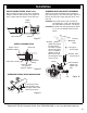
Installation INSTALL SINGLE BYPASS VALVE (cont.) Before installing the bypass valve and/or installation adaptors, make sure that the turbine and support are firmly in place inside the softener valve’s outlet port. Turbine Support Valve Outlet Turbine Valve Inlet or Outlet Plastic Clip O-Ring Plastic clip snaps into groove in bypass or adaptor Figure 8 ALTERNATE BYPASS VALVE INSTALLATION IN OUT Measure, cut (thread if needed) and put together all pipe and fittings up to the main water pipe.
Installation CONNECT THE VALVE DRAIN HOSE Take a length of 3/8” inside diameter drain tubing (supplied) and attach one end to the drain fitting (see Fig. 11). Use a tube clamp from the parts bag to hold it in place. Put the other end of the tubing over a floor drain, into a laundry tub, standpipe, or other suitable drain. Check your local codes. Leave an air gap of about 1-1/ 2'' between the end of the hose and the drain. This gap is needed so you don’t get a backflow of sewer water into the softener.
Installation LEAK TEST To check for leaks, complete the following steps: CAUTION: To avoid water or air pressure damage to softener inner parts, and to flush pipe chips or other residue from the water pipes, be sure to do the following steps exactly as instructed. 1. Fully open two nearby cold water faucets downstream from the softener. 2. Place bypass valve(s) in “bypass” position (see Figures 12 & 13). On a single valve, slide the stem inward to bypass.
Installation METAL WATER PIPE GROUNDING IMPORTANT: This water softener has a non-metallic valve system. Installing it on metal plumbing will break electrical continuity, which may interrupt grounding for the home. You must restore electrical continuity in your metal plumbing system. If you installed a 3-valve bypass system (Fig. 13), electrical continuity will be maintained. If you installed the non-metallic bypass valve (Fig.
Programming the Softener Display REGENERATION button SELECT button UP button press for tonight Select hold for immediate Set Salt Level Water Use Low Salt SET SALT LEVEL button LOW SALT indicator PROGRAM THE SOFTENER When the transformer is plugged into the electrical outlet, the model code (420) and a test number (example: J3.0), are briefly shown in the display. Then the words “PRESENT TIME” appear and 12:00 PM begins to flash.
Programming the Softener SET WATER HARDNESS NUMBER If you completed the previous step, the word “HARDNESS" should show in the display. Otherwise, press the SELECT button several times until it does. Figure 18 1. Press the r UP or s DOWN buttons to set the hardness of your water supply, in grains per gallon. The default is 25. NOTE: If your water supply contains iron, compensate for it by adding to the water hardness number. For example, assume your water is 20 gpg hard and contains 2 ppm iron.
Sanitizing the Softener SANITIZE THE WATER SOFTENER 1. Open salt lid, remove the brinewell cover and pour about 3 oz. (6 tablespoons) of household bleach into the softener brinewell. Replace the brinewell cover. 2. Make sure the bypass valve(s) is in the “service” (open) position. 3. Start a recharge: Press the REGENERATION button and hold for 3 seconds, until “RECHARGE”, “Serv” and “Fill” begin to flash in the display. This recharge draws the sanitizing bleach into and through the water softener.
Controller Features EXTRA RECHARGE Sometimes, a manually initiated recharge (regeneration) may be desired, or needed. Two examples are: = You have used more water than usual (guests visiting) and you may run out of soft water before the next automatic regeneration. = You did not add salt to the softener before it ran out. Add salt to the softener before regenerating. You can start a regeneration immediately, or you can set the controller to regenerate at the next preset recharge time (2:00 AM, or as set).
Controller Features OPTIONAL SETTINGS: = SALT EFFICIENCY = CLEAN FEATURE = CLEAN FEATURE MINUTES = 97% FEATURE = 12 / 24 HOUR CLOCK = GALLONS / LITERS = MAXIMUM DAYS BETWEEN REGENERATIONS = BACKWASH & FAST RINSE TIMES 1. To set any of these options, press and hold SELECT for 3 seconds until “000” shows in the display. Then press (do not hold) SELECT again to display one of the “Salt Efficiency” screens shown below.
Controller Features 4. Press SELECT again to display the “97%” screen. Figure 29 97% FEATURE: The 97% Feature can save salt and water by regenerating when 97% of the softener’s capacity has been used up. With this feature ON, the regeneration can occur at any time (whenever the system has reached 97% of its capacity). The default is OFF. If this feature is desired, turn it on by pressing the r UP button. 5. Press SELECT again to display the “12 or 24 hr” screen.
Controller Features 8. Press SELECT again to display the alternating screens shown in Figure 33. Figure 33 BACKWASH & FAST RINSE TIMES: If you experience salty tasting water after regeneration, you may need to increase the backwash and fast rinse times. The cycle times during regenerations are determined by the softener’s electronic controller. However, you may increase the backwash and fast rinse times, in 1 minute increments.
Controller Features WATER FLOW THROUGH THE SOFTENER To view the flow rate through the softener in gallons (or liters) per minute, press the WATER USE button. If soft water is in use, the flow rate will be displayed to the nearest tenth of a gallon (or liter). The display will show “0” when all faucets and water using appliances are off.
Care of Your Water Softener SALT BRIDGE Sometimes, a hard crust or salt “bridge” forms in the brine tank. It is usually caused by high humidity or the wrong kind of salt. When the salt “bridges,” an empty space forms between the water and the salt. Then, salt will not dissolve in the water to make brine. Without brine, the resin bed is not recharged and hard water will result. If the storage tank is full of salt, it is difficult to tell if you have a salt bridge. A bridge may be underneath loose salt.
Service Information TROUBLESHOOTING If your water softener does not work properly, make the following easy checks. Often, you will find what is wrong yourself and you won’t have to call and wait for service. If you do not find anything wrong while making the checks, and your softener still does not work properly, call your Sears Service Department. PROBLEM CAUSE No soft water No salt in the storage tank.
Service Information MANUALLY INITIATED ELECTRONIC DIAGNOSTICS 1. To enter diagnostics, press the SELECT button and hold for three seconds. The display will change to show turbine count, valve cycle position, and position switch status (open or closed).
Service Information MANUAL ADVANCE REGENERATION CHECK This check verifies proper operation of the valve motor, brine tank fill, brine draw, regeneration flow rates, and other controller functions. Always make the initial checks first, and perform the manually initiated electronic diagnostics. NOTE: The display must show a steady time (not flashing). If an error code shows, first press the SELECT button to enter the diagnostic display. 1. Press the REGENERATION button and hold in for 3 seconds.
Service Information WIRING SCHEMATIC Back of Controller (PWA) AC INPUT POS. / TURBINE MOTOR Valve Motor 24 VAC Transformer grn Turbine Sensor OUT GND +5 brn NO NC Position Switch Figure 46 Questions? Call the Kenmore Water Line 1-800-426-9345 or visit www.kenmorewater.
Water Softener Exploded View Kenmore Model No. 625.384200 1 2 Valve Assembly See Pages 28 & 29 for parts 3 4 6 5 28 27 7 26 8 9 11 10 12 13 14 Rating Decal Location 18 17 19 20 15 29 25 30 24 22 21 31 23 16 26 Questions? Call the Kenmore Water Line 1-800-426-9345 or visit www.kenmorewater.
Softener Parts List Key No. 1 7325435 2 7325451 ¢ 7 7325469 7325477 7275907 7327835 7322712 7325370 7265025 – 7112963 8 9 10 11 12 13 14 15 á 7077870 7161849 0502272 7327584 7325508 – 7327576 16 17 18 á 3 4 5 6 ¢ Part No. á á á á Description Top Cover Salt Lid (order decal & badge below) Instruction Decal Kenmore Badge Transformer, 24V, 10VA Repl. Electronic Controller (PWA) Faceplate (order decal below) Faceplate Decal Ultra Cleansing Screen Distributor O-Ring Kit (includes Key Nos.
Valve Assembly Exploded View 50 51 52 96 53 95 54 94 55 56 93 92 90 60 Wear Strip 89 87 Cross-Section View 86 91 67 68 63 84 64 83 81 82 80 66 69 57 62 85 76 58 61 Seal 88 59 74 70 65 75 78 77 72 71 73 79 28 Questions? Call the Kenmore Water Line 1-800-426-9345 or visit www.kenmorewater.
Valve Parts List Key No. 50 51 52 53 54 55 Part No. Description 7224087 7286039 7231393 0900857 7171250 7283489 – 7331169 56 57 58 59 60 – 61 62 63 64 65 66 67 68 á Screw, #8-32 x 1” (2 req.) Motor (incl. 2 ea. of Key No. 50) Motor Plate Screw, #6-20 x 3/8” (2 req.) Bearing Cam & Gear Drain Hose Adaptor Kit (incl. Key Nos. 56-60) Clip, Drain Hose Clamp Adaptor, Drain Hose O-Ring, 15/16” x 1-3/16” Flow Plug, 2.0 gpm Seal Kit (includes Key Nos.
Notes 30 Questions? Call the Kenmore Water Line 1-800-426-9345 or visit www.kenmorewater.
"– – – – – – – – – – – – – – – – – – – – – – – – – FOR IOWA USE ONLY All sales in Iowa require the following signature before consummation of sale. These signatures must be retained by seller/renter for 2 years minimum.
Get it fixed, at your home or ours! Your Home For expert troubleshooting and home solutions advice: www.managemylife.com For repair – in your home – of all major brand appliances, lawn and garden equipment, or heating and cooling systems, no matter who made it, no matter who sold it! For the replacement parts, accessories and owner’s manuals that you need to do-it-yourself. For Sears professional installation of home appliances and items like garage door openers and water heaters.