Use & Care Guide Manual de Uso y Cuidado English / Español Kenmore Liquid Propane Gas Grill ® Parrilla a gas de propano líquido Model/ Modelo: PG-4030400LD_Black PG-4030400LD-1 _ Red PG-4030400LD-2 _ Teal PG-4030400LD-3 _ Azure PG-4030400LD-4 _ Pearl P/N 30400412Z ®
DANGER If you smell gas: 1. 2. 3. 4. Shut off gas to the appliance. Extinguish any open flame. Open lid. If odor continues, keep away from the appliance and immediately call your gas supplier or your fire department. WARNING 1. Do not store or use gasoline or other flammable liquids or vapors in the vicinity of this or any other appliance. 2. An LP cylinder not connected for use shall not be stored in the vicinity of this or any other appliance.
TABLE OF CONTENTS For Your Safety……………………………………………………………………….2 Grill Service Center…………………………………………………………………...2 Product Record Information………………………………………………………...…..2 Installation Safety Precautions…………………………………………………….....…2 Safety Symbols…………………………………………………………………....…..2 Kenmore Grill Warranty……………………………………………………..……..…4 Use and Care……………………………………………………………..………...5-11 Parts List………………………………………………………………………….......12 Parts Diagram………………………………………………………………...…..…..13 Before Assembly……………………………………………………………..
WARRANTY KENMORE LIMITED WARRANTY WITH PROOF OF SALE: the following warranty coverage applies when this appliance is correctly installed, operated and maintained according to all supplied instructions. Note: Consumer is responsible for Shipping & handling of all warranty replacement parts. FOR ONE YEAR: from the date of sale this grill is warranted against defects in material or workmanship, consumer will receive free replacement parts with proof of purchase, consumer is responsible for S&H cost.
USE AND CARE DANGER • NEVER store a spare LP cylinder under or near the appliance or in an enclosed area. • Never fill a cylinder beyond 80% full. • If the information in the two points above is not followed exactly, a fire causing death or serious injury may occur. • An overfilled or improperly stored cylinder is a hazard due to possible gas release from the safety relief valve. This could cause an intense fire with risk of property damage, serious injury or death.
LP Tank Exchange Connecting Regulator To The LP Tank • Many retailers that sell grills offer you the option of replacing your empty LP tank through an exchange service. Use only those reputable exchange companies that inspect, precision fill, test and certify their cylinders. Exchange your tank only for an OPD safety feature-equipped tank as described in the "LP Tank" section of this manual. • Always keep new and exchanged LP tanks in upright position during use, transit or storage.
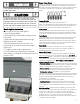
Leak Testing Valves, Hose and Regulator 1. Turn all grill control knobs to OFF. 2. Be sure regulator is tightly connected to LP tank. 3. Completely open LP tank valve by turning OPD hand wheel counterclockwise. If you hear a rushing sound, turn gas off immediately. There is a major leak at the connection. 4. Brush soapy solution onto areas where bubbles are shown in picture below: Hold coupling nut and regulator as shown for proper connection to LP tank valve.
WARNING For Safe Use of Your Grill and to Avoid Serious Injury: • Do not let children operate or play near grill. • Keep grill area clear and free from materials that burn. • Do not block holes in sides or back of grill. • Use grill only in well-ventilated space. NEVER use in enclosed space such as carport, garage, porch, covered patio, or under an overhead structure of any kind. • Do not use charcoal or ceramic briquets in a gas grill. (Unless briquets are supplied with your grill.
WARNING Turn controls and gas source or tank OFF when not in use. Burner Flame Check • Remove cooking grates and flame tamers. Light burners, rotate knobs from HIGH to LOW. You should see a smaller flame in LOW position than seen on HI. Always check flame prior to each use. If only low flame is seen refer to "Sudden drop or low flame" in the Troubleshooting Section. CAUTION If ignition does NOT occur in 5 seconds, turn the burner controls OFF, wait 5 minutes and repeat the lighting procedure.
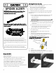
CAUTION SPIDER ALERT! SPIDER ALERT! IMPORTANT: Always ensure that the venturi burner tubes are clean. A venturi burner tube has a narrow area in which spiders tend to build nests. Cleaning the Burner Assembly Follow these instructions to clean and/or replace parts of burner assembly or if you have trouble igniting grill. 1. Turn gas off at control knobs and LP cylinder 2. Remove cooking grates and heat diffusers. 3. Remove cotter pin from rear of burners. 4.
Indirect Cooking Poultry and large cuts of meat cook slowly to perfection on the grill by indirect heat. Place food over unlit burner(s); the heat from lit burners circulates gently throughout the grill, cooking meat or poultry without the touch of a direct flame. This method greatly reduces flare-ups when cooking extra fatty cuts because there is no direct flame to ignite the fats and juices that drip during cooking.
PARTS LIST Key Description Qty Part Number Key Description Qty Part Number A01-A Lid(Black) 1 30400004A C12 Hook 6 40800123 A01-B Lid (Red) 1 30400004B C13 Side Shelf Handle 2 40800099 A01-C Lid (Teal) 1 30400004C D01 Tank holder 1 20700049 A01-D Lid (Pearl) 1 30400004D D02 Cotter pin 7 110050 A01-E Lid (Azure) 1 30400004E D03-A Grill Base (Black) 1 30400404A A02 Temperature Gauge 1 40900218 D03-B Grill Base (Red) 1 30400404B A03 Logo 1 40800106 D03-C Gr
DIAGRAM B15 A01 A02 PARTS LIST B16 A03 A04 B17 A05 A06 A07 B18 B01 B02 B03 B19 B04 C01 B05 C03 C02 B06 B07 C04 C05 B08 C06 B09 C07 C08 C09 B10 C10 B11 C11 B12 B13 B14 C12 D07 C13 D08 D12 D13 D14 D01 D02 D03 D15 D04 D09 D06 D05 D10 D11 13
BEFORE ASSEMBLY NOTICE: Once you have unpacked the grill, check all the grill parts against the pictures on this and the following two pages. If any parts are missing or damaged, please call 1-888-287-0735.
BEFORE ASSEMBLY 15
BEFORE ASSEMBLY 16
Grill Base Turn the Grill Base upside down. Remove the Tank Holder from the underside of the base. Set tank holder aside. Use (4) M6x13 screws each to attach the Swivel Caster to the corner on your left and the Standard Caster to the corner on your right.
1 2 Grill Base Twist each Swivel Caster with Brake into the other two corners of the grill base. Use the wrench provided to firmly tighten the casters in place. Turn the grill base right side up. Insert the ends of the tank holder into the two holes as shown. Turn the grill base upside down. Insert a cotter pin into each end of the tank holder to secure in place.
Pedestal Attach but do not fully tighten the panel support angle bars to left and right side panels with (2) M4x10 screws. Attach (3) M4x10 screws to left and right side panels as shown, leaving a 1/8" - 5/32" gap between panel and head of screw.
Pedestal A- Attach front panel to left side panel. Push wide ends of key holes over screw heads and slide front panel down. Fully tighten screws. B- Attach front panel to right side panel. Push wide ends of key holes over screw heads and slide front panel down. Fully tighten screws.
Pedestal Use (6) M6x13 screws as shown to attach pedestal panels to grill base. Use (2) M4x10 screws as shown to attach each panel support angle bar to grill base. Fully tighten screws left partially tightened in step 3.
9 Pedestal Use (6) M4x10 screws to attach the Back Rail to the rear of the pedestal as shown.
Grill Head to Pedestal CAUTION: To avoid possible injury, two people are required to perform this step. Remove any wire ties holding the regulator and gas hose under the grill head, making sure the hose hangs freely. With the aid of an assistant, carefully lower the grill head onto the pedestal. While your assistant steadies the grill head on the pedestal, use (4) M6x13 screws from underneath grill head to attach head to pedestal.
Attach the 4 side shelf support brackets to firebox with (8) M6x13 screws, as shown. There is a location label on each bracket.
Folding Side Shelves Perform the procedure below for both the Left and Right Side Shelf. Left side is shown below. Slide 3 accessory hooks onto the shelf handle in the orientation shown below. Hook ends must face away from grill body. Remove the screws, lock washers and flat washers preattached to the handle ends, and use them to attach the handle to the shelf. Screw (1) M6x12 shoulder screws into the lower hole of each shelf support bracket.
Raise and Lower Shelves To raise the shelves, grasp shelf by sides and lift up until slots at bottom of shelf braces clear lower shoulder screws in shelf support brackets. Lower shelf slightly for slots to secure onto screws. To lower the shelves, grasp shelf by sides and lift up to raise brace slots from bracket shoulder screws. Fold shelf down into position at side of pedestal.
Heat Diffusers, Cooking Grids, Warming Rack: Place heat diffusers over burners. Diffusers will fit in firebox in either direction. Fit tabs in firebox front through slots in diffuser tips. Fit diffuser tips beside tabs in firebox rear. Place cooking grates onto grate rests. Insert the tabs at the back of the warming rack into the holes in the rear panel.
EMERGENCIES: If a gas leak cannot be stopped, or a fire occurs due to gas leakage, call the fire department. Problem Possible Cause Gas leaking from cracked/cut/burned hose. • Damaged hose. Gas leaking from LP cylinder. • Mechanical failure due to rusting or mishandling. Gas leaking from LP cylinder valve. • Failure of cylinder valve from mishandling or mechanical failure. Gas leaking between LP • Improper installation, connection not cylinder and regulator tight, failure of rubber seal. connection.
Troubleshooting (continued) Problem Possible Cause Burner(s) will not light using igniter. (See Electronic Ignition Troubleshooting also) ELECTRONIC IGNITION: • No spark, no ignition noise. Pro • Sparks, but not at electrode or at full strength. Burner(s) will not match light. • See “GAS ISSUES:” on previous page. • Match will not reach. • Improper method of match-lighting. Sudden drop in gas flow or low flame. • Out of gas. • No spark, some ignition noise. • Excess flow valve tripped.
Troubleshooting - Electronic Ignition Problem Possible Cause Check Item Prevention/Solution SECTION I No sparks appear at any electrodes when control knob turned to HI: no noise can be heard from spark module. • Battery not installed properly. • Dead battery. • Button assembly not installed properly. • Faulty spark module. • Check battery orientation. • Has battery been used previously? • Check to insure threads are properly engaged. Button should travel up and down without binding.
PELIGRO Si siente olor a gas: 1. Cierre el paso de gas al aparato. 2. Apague toda llama al descubierto. 3. Abra la tapa. 4. Si persiste el olor, aléjese del aparato y llame inmediatamente al proveedor local de gas o a los bomberos. ADVERTENCIA 1. No guarde ni use gasolina ni otros líquidos o gases inflamables cerca de éste ni de cualquier otro aparato. 2. No guarde un tanque de gas propano, que no esté conectado, cerca de éste ni de cualquier otro aparato.
TABLA DE CONTENIDO Por tu seguridad……………………………………………………………………..33 Grill Service Center………………………………………………………………...33 Información del registro del producto……………………………………….…....….....33 Precauciones de seguridad de instalación………………………………….….….....…33 Símbolos de seguridad………………………………..……………………….......…..33 Garantía de la parrilla Kenmore……………………………….…………………..…35 Uso y cuidado……………………………………………...……………....……...36-42 Lista de partes……………………………………………………………...……........43 Diagrama de piezas………………………………………………………….
GARANTÍA GARANTÍA LIMITADA DE KENMORE CON LA PRUEBA DE VENTA: se aplica la siguiente cobertura de garantía cuando este dispositivo se instala, opera y mantiene correctamente de acuerdo con todas las instrucciones suministradas. Nota: El consumidor es responsable del envío y manejo de todas las piezas de repuesto bajo garantía.
UOS Y MANTENIMIENTO PELIGRO • NUNCA guarde los cilindros de gas de repuesto debajo del aparato, cerca del mismo, ni en áreas cerradas. Nunca cargue el tanque con más del 80% de su capacidad. • Los tanques de gas propano de repuesto sobrecargados o mal llenados son peligrosos, ya que la válvula de seguridad puede dejar salir gas. Esto puede provocar incendios intensos que pueden causar daños materiales, lesiones graves o la muerte.
Cambio del tanque de gas • Muchos comerciantes minoristas que venden parrillas, le ofrecen la opción de cambiar su tanque de gas vacío mediante un servicio de recambio. Emplee únicamente empresas de recambio de buena reputación, que inspeccionen, carguen con precisión, verifiquen y certifiquen sus cilindros. Cambie su tanque sólo por otros tanques equipados con el dispositivo de seguridad volumétrica que se describe en la sección de Tanques de gas de este manual.
Prueba para detectar fugas de las válvulas, las mangueras y el regulador Sostenga la tuerca de unión y el regulador, como se ilustra, para conectarlos bien a la válvula del tanque. 6. Gire la tuerca de unión en el sentido de las agujas del reloj, apretándola hasta que no se mueva más. El regulador formará un sello en el dispositivo de seguridad de la válvula del tanque, lo que creará cierta resistencia.
ADVERTENCIA Para usar su parrilla en forma segura y para evitar lesiones graves: • No deje que los niños usen la parrilla ni que jueguen cerca de la misma. • Mantenga el área de la parrilla limpia y sin materiales combustibles. • No obstruya los agujeros laterales ni los de la parte posterior de la parrilla. • Revise periódicamente las llamas del quemador. • Use la parrilla sólo en lugares bien ventilados.
ADVERTENCIA Gire los controles y la fuente de gas o el tanque a la posición OFF cuando no esté en uso. Comprobación de llama del quemador • Retire las parrillas de cocción y los domadores de llama. Encienda los quemadores, gire las perillas de ALTO a BAJO. Debería ver una llama más pequeña en posición BAJA que la que se ve en HI. Siempre revise la llama antes de cada uso. Si solo se ve poca llama, consulte "Caída repentina o llama baja" en la sección de solución de problemas.
CAUTION ¡ALERTA CONTRA IMPORTANT: Asegúrese siempre de que los tubos venturi estén limpios.Un tubo de venturi del quemador tiene un área estrecha en la que las arañas tienden a construir nidos. Cómo limpiar la unidad del quemador Siga estas instrucciones para limpiar o cambiar piezas de la unidad del quemador, o si tiene problemas para encender la parrilla. 1. Cierre el paso de gas en las perillas de control y desde el tanque de gas. 2. Retire las parrillas de cocción y Termodisipador. 3.
Cocina indirecta B carne se cocinan Las aves de corral y los grandes cortes de lentamente a la perfección en la parrilla por calor indirecto. Coloque los alimentos sobre los quemadores sin encender; el calor de los quemadores iluminados circula suavemente por toda la parrilla, cocinando carne o aves sin tocar una llama directa. Este método reduce en gran medida los brotes cuando se cocinan cortes grasos extra porque no hay llama directa para encender las grasas y los jugos que gotean durante la cocción.
LISTA DE PIEZAS Llave Descripción Qty Numero de Llave parte A01-A Tapa (Negro) 1 A01-B Tapa (Roja) 1 A01-C Tapa (Trullo) 1 A01-D Tapa (Perla) 1 30400004D A01-E Tapa (Azur) 1 A02 Indicador de temperatura 1 A03 A05 Logo Tapa del parachoques de goma, delantero Mango de espaciador de aislamiento A06 Bisagra de la manija de la tapa A07 Mango de la tapa B01 B02 Qty Numero de parte 40800123 C12 Gancho 6 30400004B C13 Empuñadura lateral del estante 2 40800099 30400004C D01
DIAGRAM B15 A01 A02 B16 A03 A04 B17 A05 A06 A07 B18 B01 B02 B03 B19 B04 C01 B05 C03 C02 B06 B07 C04 C05 B08 C06 B09 C07 C08 C09 B10 C10 B11 C11 B12 B13 B14 C12 D07 C13 D08 D12 D13 D14 D01 D02 D03 D15 D04 D09 D10 D11 44 D06 D05
ANTES DE LA ENSAMBLAJE AVISO: Una vez que haya desempacado la parrilla, verifique todas las partes de la parrilla contra las imágenes en esta y las dos páginas siguientes. Si falta alguna pieza o está dañada, llame al 1-888-287-0735.
ANTES DE LA ENSAMBLAJE 46
ANTES DE LA ENSAMBLAJE 47
Parrilla de la base Coloque la base de la parrilla boca abajo. Retire el soporte del tanque de la parte inferior de la base. Coloque el soporte del tanque a un lado. Use (4) tornillos M6x13 cada uno para sujetar la Ruedita Giratoria a la esquina a su izquierda y la Ruedita Estándar a la esquina a su derecha.
1 2 50 Parrilla de la base Gire cada Ruedita giratoria con freno en las otras dos esquinas de la base de la parrilla. Use la llave provista para apretar firmemente las ruedas en su lugar. Levante la base de la parrilla hacia arriba. Inserte los extremos del soporte del tanque en los dos orificios como se muestra. Coloque la base de la parrilla boca abajo. Inserte un pasador de chaveta en cada extremo del soporte del tanque para asegurarlo en su lugar.
Pedestal Fije pero no ajuste completamente las barras angulares del soporte del panel a los paneles laterales izquierdo y derecho con (2) tornillos M4x10. Conecte (3) tornillos M4x10 a los paneles laterales izquierdo y derecho como se muestra, dejando un espacio de 1/8 "a 5/32" entre el panel y la cabeza del tornillo.
Pedestal A- Coloque el panel frontal en el panel lateral izquierdo. Empuje los extremos anchos de los orificios de la llave sobre los cabezales de los tornillos y deslice el panel frontal hacia abajo. Apriete completamente los tornillos. B- Coloque el panel frontal en el panel lateral derecho. Empuje los extremos anchos de los orificios de la llave sobre los cabezales de los tornillos y deslice el panel frontal hacia abajo. Apriete completamente los tornillos.
Pedestal Utilice (6) tornillos M6x13 como se muestra para unir los paneles de pedestal a la base de la parrilla. Use (2) tornillos M4x10 como se muestra para unir cada barra de ángulo de soporte del panel a la base de la parrilla. Apriete completamente los tornillos que quedaron parcialmente apretados en el paso 3.
Pedestal Utilice (6) tornillos M4x10 para sujetar el riel trasero a la parte posterior del pedestal como se muestra.
Grill Head al Pedestal PRECAUCIÓ N: para evitar posibles lesiones, se requiere que dos personas realicen este paso. Retire las ataduras de alambre que sujetan el regulador y la manguera de gas debajo de la cabeza de la parrilla, asegurándose de que la manguera cuelgue libremente. Con la ayuda de un asistente, baje cuidadosamente la cabeza de la parrilla sobre el pedestal.
Fije los 4 soportes de soporte del estante lateral a la cámara de combustión con (8) tornillos M6x13, como se muestra. Hay una etiqueta de ubicación en cada soporte.
Estantes laterales plegables Realice el siguiente procedimiento tanto para el estante del lado izquierdo como del lado derecho. El lado izquierdo se muestra a continuación. Deslice los 3 ganchos de accesorios en el mango del estante en la orientación que se muestra a continuación. Los extremos del gancho deben quedar alejados del cuerpo de la parrilla. Retire los tornillos, las arandelas de seguridad y las arandelas planas preattached a los extremos del mango, y úselas para unir el mango al estante.
Elevar y bajar estanterías Para levantar los estantes, agarre el estante por los lados y levántelo hasta que las ranuras en la parte inferior del estante se apoyen en los tornillos inferiores para los hombros en los soportes de estantería. Estante inferior ligeramente para ranuras para asegurar en los tornillos. Para bajar los estantes, agarre el estante por los lados y levántelo para elevar las ranuras de soporte de los tornillos de los hombros del soporte.
Difusores de calor, rejillas de cocina, bastidor de calentamiento: Coloque los difusores de calor sobre los quemadores. Los difusores cabrán en la cámara de combustión en cualquier dirección. Coloque las lengüetas en el frente de la cámara de combustión a través de las ranuras en las puntas del difusor. Coloque las puntas del difusor al lado de las pestañas en la parte posterior de la cámara de combustión. Coloque las rejillas de cocción en los soportes de la rejilla.
EMERGENCIAS: si no se puede detener una fuga de gas o si se produce un incendio debido a una fuga de gas, llame al departamento de bomberos. Causa posible Problema Fuga de gas de la manguera agrietada / • Manguera dañada cortada / quemada. • Falla mecánica debido a la oxidación Fuga de gas del o maltrato cilindro de LP. • Falla de la válvula del cilindro por mal Fuga de gas de la manejo o falla mecánica. válvula de cilindro de • Instalación incorrecta, conexión no LP. apretada, falla de sello de goma.
Solución de problemas (continuación) Problem Possible Cause Los quemadores no se encenderán con el encendedor. (Consulte también Solución de problemas de encendido electrónico) IGNICIÓ N ELECTRÓ NICA: • Sin chispas, sin ruido de ignición. Pro Los quemadores no coincidirán con la luz. • Prevention / Solution Prevention/Solution Sin chispas, algún ruido de ignición. • Chispas, pero no en el electrodo o en su totalidad fuerza. • Vea "PROBLEMAS DE GAS:" en la página anterior.
Resolución de problemas – Encendido electrónico Problema (encendido) Causas probables Procedimiento de revisión Medidas de prevención / solución SECCIÓN I • La pila no está • Revise la orientación de la pila. • Instale la pila (verifique que los polos “+” y No aparecen chispas en instalada • ¿Es una pila usada? “–” estén orientados correctamente, con el ningún electrodo cuando se adecuadamente.
NOTES