
Use and Care Guide


27
8
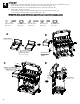
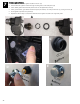
Burner Electrode and Igniter Cover
□ Place the 4 burner Electrode wires (thin black) and the Pulse Control Line through the pre-installed side panel
clamp. (A).
Note: If wires are difficult to install, loosen the clamp screw, put the wires through the clamp and retighten the
screw.
□ Place the 4 thin black wires into the 4 narrow slots in the electronic ignition module. Place the Pulse Control Line into
the wide slot. (B)
Note: The direction must be the same as shown. (C).
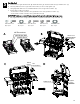
□ Remove the (2) M4x10 screws pre-assembled to the Pulse Decoration Box. (D)
□ Attach a Pulse Decoration Box to each side panel (both left and right) with the previously removed screws as
shown in (E).
□ Set the wires in the groove of each pulse decoration box as shown. (F)(G)
A
B
C
D
E
F
G