Use & Care Guide Manual de Uso y Cuidado English / Español Model/Modelo: 146.23681310 Item / Artículo: 640-050057376-5 Kenmore Liquid Propane Gas Grill ® Parrilla de LP gas P/N 61200342 Sears Brands Management Corporation Hoffman Estates, IL 60179 U.S.A. www.kenmore.com www.sears.com www.kmart.
DANGER If you smell gas: 1. 2. 3. 4. Shut off gas to the appliance. Extinguish any open flame. Open lid. If odor continues, keep away from the appliance and immediately call your gas supplier or your fire department. WARNING 1. Do not store or use gasoline or other flammable liquids or vapors in the vicinity of this or any other appliance. 2. An LP cylinder not connected for use shall not be stored in the vicinity of this or any other appliance.
TABLE OF CONTENTS For Your Safety . . . ..2 Grill Service Center. . . ..2 Product Record Information . . . .2 Installation Safety Precautions . . . ..2 Safety Symbols . . . ..2 Kenmore Grill Warranty . . . Use and Care . . . Parts List . . . Parts Diagram . . . Before Assembly . . . .3 . . . 4-10 . . . 11 . . 13 . . . 14-17 Assembly . . . . 18-46 Troubleshooting . . . .
WARRANTY WARRANTY KENMORE GRILL WARRANTY ..2 ..2 KENMORE GRILL WARRANTY Kenmore One Year Limited Warranty One Year Full Warranty on Kenmore Grill .2 When installed, operated and maintained according to all supplied instructions, if this appliance fails due to a defect in material and workmanship within one year from the date. .of2 purchase, call 1-800-4-MY-HOME® to arrange for free repair or replacement if repair is unavailable. ..2 . 3 through will be replaced free of charge.
USE AND CARE DANGER • NEVER store a spare LP cylinder under or near the appliance or in an enclosed area. • Never fill a cylinder beyond 80% full. • If the information in the two points above is not followed exactly, a fire causing death or serious injury may occur. • An overfilled or improperly stored cylinder is a hazard due to possible gas release from the safety relief valve. This could cause an intense fire with risk of property damage, serious injury or death.
LP Tank Exchange Connecting Regulator To The LP Tank • Many retailers that sell grills offer you the option of replacing your empty LP tank through an exchange service. Use only those reputable exchange companies that inspect, precision fill, test and certify their cylinders. Exchange your tank only for an OPD safety feature-equipped tank as described in the "LP Tank" section of this manual. • Always keep new and exchanged LP tanks in upright position during use, transit or storage.
Leak Testing Valves, Hose and Regulator 1. Turn all grill control knobs to OFF. 2. Be sure regulator is tightly connected to LP tank. 3. Completely open LP tank valve by turning OPD hand wheel counterclockwise. If you hear a rushing sound, turn gas off immediately. There is a major leak at the connection. Correct before proceeding by calling Sears for replacement parts at 1-800-4-MY-HOME®. 4.
WARNING For Safe Use of Your Grill and to Avoid Serious Injury: • Do not let children operate or play near grill. • Keep grill area clear and free from materials that burn. • Do not block holes in sides or back of grill. • Use grill only in well-ventilated space. NEVER use in enclosed space such as carport, garage, porch, covered patio, or under an overhead structure of any kind. • Do not use charcoal or ceramic briquets in a gas grill. (Unless briquets are supplied with your grill.
WARNING Turn controls and gas source or tank OFF when not in use. Burner Flame Check • Remove cooking grates and flame tamers. Light burners, rotate knobs from HIGH to LOW. You should see a smaller flame in LO position than seen on HI. Always check flame prior to each use. If only low flame is seen refer to "Sudden drop or low flame" in the Troubleshooting Section. CAUTION If ignition does NOT occur in 5 seconds, turn the burner controls OFF, wait 5 minutes and repeat the lighting procedure.
CAUTION SPIDER ALERT! SPIDER ALERT! IMPORTANT: Always ensure that the venturi burner tubes are clean. A venturi burner tube has a narrow area in which spiders tend to build nests. Cleaning the Burner Assembly Follow these instructions to clean and/or replace parts of burner assembly or if you have trouble igniting grill. 1. Turn gas off at control knobs and LP cylinder 2. Remove cooking grates and heat diffusers. 3. Remove cotter pin from rear of burners. 4.
Indirect Cooking Poultry and large cuts of meat cook slowly to perfection on the grill by indirect heat. Place food over unlit burner(s); the heat from lit burners circulates gently throughout the grill, cooking meat or poultry without the touch of a direct flame. This method greatly reduces flare-ups when cooking extra fatty cuts because there is no direct flame to ignite the fats and juices that drip during cooking. 1 Burner Cooking Cook with direct or indirect heat. Best for smaller meals or foods.
PARTS LIST Key Description Key Qty Description 1 1 Warming Rack 2 1 22 Cooking Grate 3 1 3 Heat Diffuser 4 1 45 Grease Tray 1 2 Burner Grid 56 Side 7 1 Side Shelf 6 Right 8 1 7 Side Burner Base 9 1 1 Burner 810 Side 11 1 912 Side Burner Lid 1 1013 Rotate Axis, Side Burner Lid 1 1 1114 Ingiter Wire, Side Burner 15 1 12 Fascia, Right Side Shelf 16 1 1317 Control Knob Bezel, Side Burner 2 2 1418 Control Knob 19 1 15 Side Shelf Bracket 20 1 1621 Folding Side Shelf 1 3 Heat Shield 1722 Tank 23 1 Heat Shield Br
PARTS LIST Key Description Key Qty Description 691 Lower Door Magnet Box 2 1 702 Caster 3 1 71 Back Bottom Support Bar 4 1 725 Front 1 Bottom Support Bar 2 Door, Main Cabinet 736 Left 7 1 74 Hook 8 1 75 Push Bar 9 1 7610 Left 1 Side Shelf 1 Bar B 7711 Slider 12 1 78 Drawer Seat 13 1 7914 Drawer Handle 1 1 8015 Drawer Fascia 16 1 81 Back Panel, Left Cabinet 17 2 8218 Match Holder Bracket 2 8319 Match Holder 1 1 Panel, Main Cabinet 8420 Left 21 1 85 Left Panel, Left Cabinet 22 3 8623 Left 1 Module Bracket 2
DIAGRAM PARTS LIST 14 • 146.
BEFORE ASSEMBLY READ AND FOLLOW THE INSTRUCTIONS BELOW TO CORRECTLY UNPACK GRILL PARTS FROM SHIPPING BOX. Step 1: Once you open the top of the shipping box, grasp box by the top flaps and raise it up and away from the packaged grill. Take out the Hardware Pack, manual, right bottom shelf and tank heat shield from top, also take out left cabinet shelf from side. Next remove the door bracket, back rail and back panel from front. Remove all parts from plastic bags. 146.
BEFORE ASSEMBLY Step 2: Continue to remove the left panel of left cabinet, right panel of right cabinet, right cabinet door, left cabinet door, push bar with hooks and door handles from top. Next, remove the left bottom shelf, left panel and right panel of main cabinet, back and front bottom support bars and warming rack. Remove all parts from plastic bags. 16 • 146.
BEFORE ASSEMBLY Step 3: Remove the right panel of main cabinet, door brackets of left and right cabinets, left panel of main cabinet and doors of main cabinet from back. With the aid of an assistant, turn grill head over on its side as shown in the second figure below, and remove the top Styrofoam piece. 146.
BEFORE ASSEMBLY Step 4: With the aid of an assistant, lift the grill head out of the bottom styrofoam piece. Place it upright on the other Styrofoam piece as the first figure show. Open grill lid, and take out the small boxes packed within the grill head. Remove all packing materials, and remove all parts from boxes. 18 • 146.
ASSEMBLY CAREFULLY READ AND PERFORM ALL ASSEMBLY INSTRUCTIONS ON THE FOLLOWING PAGES. Tools Required: Adjustable wrench (not provided) Screwdriver (not provided) 7/16” Combination wrench (not provided) The following hardware is provided in a blister pack for convenient use.
Bottom Shelf Remove tank holder from bottom shelf with tank hole. Turn both bottom shelves upside down. Align and connect them with (5) M6x13 Screws and M6 Nuts as shown. Tighten securely. M6X13 screw Qty: 5 pcs M6 Nut Qty: 5 pcs 20 • 146.
Bottom Shelf (continued) IMPORTANT: Double check the positioning of all parts in this step before inserting and tightening screws. Insert the two bottom shelf support bars through the square holes at middle of bottom shelf as shown. Note: Insert the support bar with square cutouts at the rear of the bottom shelf. Align the screw holes on bars with the holes on bottom shelf. Once in position, push down hard on the bars to snap them all the way down.
Casters Turn bottom shelf upside down. Attach casters to bottom shelf with (16) M6x13 screws. IMPORTANT: Install each caster into the correct position as shown in the figure below. Turn shelf right side up. Attach main cabinet door magnets to shelf with (2) M4x10 screws. 1 2 M6X13 screw Qty: 16 pcs Swivel Caster M4X10 screw Qty: 2 pcs Swivel Caster with Brake 22 • 146.
1 2 Cotter pin Tank Holder Insert the tank holder ends into the holes on bottom shelf as shown. Turn the shelf upside down, and use (2) cotter pins to secure the ends under the shelf. Qty: 2pcs 146.
Grill Cart Main Cabinet To attach main cabinet side panels, align panel bottom holes with holes on bottom shelf. Right Side panel has a square hole cutout as show. Attach left and right panels to bottom shelf with (4) M6x13 screws. Attach back panel to bottom shelf and side panels with (6) M4x10 screws. M6X13 screw Qty: 4 pcs M4X10 screw Qty: 6 pcs 24 • 146.
Grill Cart Main Cabinet ( continued) Attach tank baffle bar to back panel and bottom shelf with (2) M4x10 screws. Align the holes in the cart support angle bars with holes on bottom shelf and side panels. Attach angle bars with (8) M4x10 screws. M4X10 screw Qty: 10 pcs 146.
Grill Cart Left Cabinet Attach back panel of left cabinet to bottom shelf and main cabinet left panel with (5) M4x10 screws. Note: Left cabinet back panel has two holes in middle. Fit back edge of left cabinet outer panel over left cabinet back panel. Attach left cabinet outer panel to bottom shelf and left cabinet back panel with (6) M4x10 screws. Note: Left cabinet outer panel has drawer slide at top. Insert left cabinet shelf into place, and secure with (6) M4x10 screws as show.
9 Grill Cart Right Cabinet Attach back panel of right cabinet to bottom shelf and main cabinet right panel with (5) M4x10 screws. Fit back edge of right cabinet outer panel over right cabinet back panel. Attach right cabinet outer panel to bottom shelf and right cabinet back panel with (6) M4x10 screws. Insert right cabinet tank baffle into place, and secure with (4) M4x10 screws as shown. M4X10 screw Qty: 15 pcs A C 146.
Door Brackets Insert main cabinet door bracket into place between main cabinet side panels as shown. Note: Be sure to position bracket with magnets at bottom. Use (2) M4x10 screws to attach hinge end of left cabinet door bracket to left cabinet outer panel. Use (2) M4x10 screws to attach magnet end of bracket through main cabinet panel to main cabinet door bracket. Use (2) M4x10 screws to attach hinge end of right cabinet door bracket to right cabinet outer panel.
Side Cabinet Door Magnets Attach left cabinet door magnets to main cabinet side panel with (2) M4x10 screws. Attach right cabinet door magnets to main cabinet side panel with (2) M4x10 screws. M4X10 screw Qty: 4 pcs 146.
Ignition Modules Attach left ignition module box to main cabinet left panel with (4) M4x10 screws. Also attach ignition wire clip to panel with (1) M4x10 screw as shown. Attach right ignition module box to main cabinet right panel with (4) M4x10 screws. Also attach ignition wire clip to panel with (1) M4x10 screw as shown. M4X10 screw 30 • 146.
13 Heat Insulation Panel Attach heat insulation panel to door bracket and right side panel with (5) M4x10 screws. Attach heat insulation panel bracket to heat insulation panel and back panel with (2) M4x10 screws as shown. M4X10 screw Qty: 7 pcs 146.
Grill Head to Cart This step requires two people to lift and position grill head onto cart. If not already done, remove tie wraps securing regulator hose and ignition wires to underside of grill head. Pull hose out to side of main cabinet. Carefully lower grill head onto the cart. Make sure the regulator hose hangs outside the main cabinet and into the right cabinet. Left ignition wires hang directly into the main cabinet.
Left Side Shelf Place left side shelf on top of left cabinet as shown A. Attach shelf to grill head with (2) M6x13 screws and M6 compression washers from inside of firebox as shown B. Attach shelf to left cabinet with (4) M4x10 screws as shown C. 13 M6X13 screw M4X10 screw A Qty: 2 pcs Qty: 4 pcs M6 compression washer Qty: 2 pcs B C 146.
Drawer Attach slide bars to sides of drawer with (4) M4x8 screws and M4 nuts as shown A. Attach drawer to front panel with (7) M4x10 screws as shown B. Pull the two cabinet slide bars (C) all the way out. Insert drawer side bars into cabinet slide bars and push drawer all the way in. 13 M4X8 screw Qty: 4 pcs M4X10 screw Qty: 7 pcs M4 nut Qty: 4 pcs A B C 34 • 146.
Drawer (continued) If drawer front panel is not perfectly aligned with cabinet, the drawer can removed and adjusted. To remove, slide drawer out all the way. Push down on left side drawer slide lock pin and pull up on right side drawer slide lock pin. Pull drawer free from cabinet slides. See A. To adjust vertical alignment, loosen front and/or rear drawer slide fasteners. Adjust position of drawer and retighten fasteners. See B.
13 Push Bar Attach push bar to left side panel with (4) M6x17 screws as shown. Note: Hook ends must face away from grill. M6X17 screw Qty: 4 pcs 36 • 146.
13 Right Side Shelf Attach right side shelf fascia to right side shelf with (2) M5x10 screws and M5 flat washers as shown A. Place right side shelf on top of right cabinet as shown B. Attach shelf to grill head with (2) M6x13 screws and M6 compression washers from inside of firebox as shown C. A M5X10 screw Qty: 2 pcs M5 flat washer Qty: 2 pcs M6X13 screw Qty: 2 pcs M6 compression washer Qty: 2 pcs C B 146.
13 Right Side Shelf (continued) Attach shelf to right cabinet with (6) M4x10 screws as shown A. Attach right side shelf fascia to control panel with (1) M4x10 screw as shown B. A M4X10 screw Qty: 7 pcs B 38 • 146.
13 Folding Side Shelf Attach the two folding side shelf support brackets to the outer panel of right cabinet with (4) M6x17 screws. Place the bracket as figure A show, make sure the pre-assemble M6x12 screws are in the lower holes of support brackets. Align slots in shelf supports with upper holes in support brackets as shown B. Hold shelf in place while attaching shelf to brackets with (2) M6x12 shoulder screws. Raise shelf and push down to lock into position as shown C.
13 40 • 146.23686310 Side Burner Loosen side burner in side shelf by unscrewing and removing the two front screws holding the burner in place. See A. Note: Do not loosen electrode screw. Side burner black ground line has two wires running into one connector tip. Run longer wire through vent hole above ignition module in side panel into right cabinet. Securely attach tip of long wire to connector pin on regulator valve assembly. See B.
13 Wires for Right Ignition Module Connect the three black wires with the small tips into three of four small sockets as shown, connect the orange side burner ignition wire with small tip into remaining small socket. See figure B. Connect the large tipped orange wire into the orange marked large socket as shown. See figure C. Connect the large tipped dual wire into the remaining large socket as shown. See figure D.
13 Wires for Left Ignition Module Connect the three black wires with the small tips into three of the four small sockets as shown. Connect the small tip of the dual orange wire into the remaining small socket as shown. Connect the large tip of the dual orange wire into the orange marked large socket as shown. Connect the large tipped black wire into the remaining large socket as shown. Gather the five wires together and push them into the ignition wire clip to store them neatly out of the way.
13 Main Cabinet Grill Doors Remove the (4) M5x15 screws pre-assembled to the main cabinet door handle ends, and use them to attach handles to doors as shown. For each door, insert the bottom hinge pin into the hole in the cart bottom shelf (A). Push the top hinge pin down into the door, align it with the top hinge pin hole (B), and let the pin pop back up, securing the door in position(C).
Cabinet Doors Remove the (4) M5x15 screws pre-assembled to the door handles ends, and use them to attach handles to doors. Attach the tool hook at back of left cabinet door with (3) M4x10 screws. For each door, insert the bottom hinge pin into the hole in the front bottom of the cart. (A) Push the top hinge pin down into the door, align it with the top hinge pin hole, (B) and let the pin pop back up, securing the door in position.
13 Grease Tray, Heat Diffusers, Cooking Grates, and Warming Rack Slide the grease tray into bottom of firebox from back. Make sure the grease drainage hole is on the right side, as seen from back of the grill. Place heat diffusers over main burners. The heat diffusers will fit in firebox in either direction. Fit tabs in firebox front through slots in diffuser tips. Fit diffuser tips between tabs in firebox rear. Place cooking grates onto grate rests at front and rear of firebox.
13 46 • 146.23686310 Grease Cup and Match Holder Place grease cup into grease cup clip. Hang grease cup clip from bottom of grease tray as shown. Insert the nylon twist clamp into the hole in rear of main cabinet left side panel as shown. Use it to attach match holder to grill.
13 LP Tank Feed the regulator hose through the hole in the right side panel. LP tank is sold separately. Use only with an OPD (Overfill Protection Device) equipped LP tank. Fill and leak check before attaching to grill and regulator. Place LP tank into hole in bottom shelf with tank collar opening facing to the right as shown. Raise tank holder to hold LP tank securely in place.
EMERGENCIES: If a gas leak cannot be stopped, or a fire occurs due to gas leakage, call the fire department. Problem Gas leaking from cracked/cut/burned hose. Possible Cause • Damaged hose. Gas leaking from LP cylinder. • Mechanical failure due to rusting or mishandling. Gas leaking from LP cylinder valve. • Failure of cylinder valve from mishandling or mechanical failure. Gas leaking between LP • Improper installation, connection not cylinder and regulator tight, failure of rubber seal. connection.
Troubleshooting (continued) Problem Possible Cause Burner(s) will not light using igniter. (See Electronic Ignition Troubleshooting also) ELECTRONIC IGNITION: • No spark, no ignition noise. • No spark, some ignition noise. Pro • Sparks, but not at electrode or at full strength. Burner(s) will not match light. • See “GAS ISSUES:” on previous page. • Match will not reach. • Improper method of match-lighting. Sudden drop in gas flow or low flame. • Out of gas. • Excess flow valve tripped.
Troubleshooting - Electronic Ignition Problem Possible Cause • Battery not installed SECTION I No sparks appear at properly. any electrodes when • Dead battery. control knob turned to HI: no noise can be heard from spark • Button assembly not module. installed properly. • Faulty spark module. SECTION II No sparks appear at any electrodes when control knob turned to HI; noise can be heard from spark module.
PELIGRO Si siente olor a gas: 1. Cierre el paso de gas al aparato. 2. Apague toda llama al descubierto. 3. Abra la tapa. 4. Si persiste el olor, aléjese del aparato y llame inmediatamente al proveedor local de gas o a los bomberos. ADVERTENCIA 1. No guarde ni use gasolina ni otros líquidos o gases inflamables cerca de éste ni de cualquier otro aparato. 2. No guarde un tanque de gas propano, que no esté conectado, cerca de éste ni de cualquier otro aparato.
ÍNDICE DE MATERIAS Por su propia seguridad . . . . . . 51 Centro de servicio para parrillas.. . . . . 51 Información de inscripción de la garantía . . . . 51 Símbolos de seguridad . . . . . 51 Medidas de seguridad para la instalación . . . . . 51 Garantía para la parrilla Kenmore . . . .53 Uso y mantenimiento . . . . ..54-60 Lista de piezas . . . . . . 61-62 Vista esquemática de las piezas . . . .. . 63 .. . 64-67 Armado . . . Antes De La Asamblea . . . . 68-96 Resolución de problemas .
GARANTÍA WARRANTY ..2 Garantía completa de un año para la parrilla Kenmore ..2 Garantía limitada de un año de Kenmore KENMORE GRILL WARRANTY Si esta parrilla falla debido a defectos de material o de mano de obra dentro del plazo un año desde la fecha deGrill One Year Full de Warranty on Kenmore .2 compra, llame al 1-800-4-MY-HOME® ón gratuita (o el cambio si la reparación resulta imposible de realizar) . 2 through will be replaced free of charge.
UOS Y MANTENIMIENTO PELIGRO • NUNCA guarde los cilindros de gas de repuesto debajo del aparato, cerca del mismo, ni en áreas cerradas. • Nunca cargue el tanque con más del 80% de su capacidad. • Los tanques de gas propano de repuesto sobrecargados o mal llenados son peligrosos, ya que la válvula de seguridad puede dejar salir gas.Esto puede provocar incendios intensos que pueden causar daños materiales, lesiones graves o la muerte.
Cambio del tanque de gas • Muchos comerciantes minoristas que venden parrillas, le ofrecen la opción de cambiar su tanque de gas vacío mediante un servicio de recambio. Emplee únicamente empresas de recambio de buena reputación, que inspeccionen, carguen con precisión, verifiquen y certifiquen sus cilindros. Cambie su tanque sólo por otros tanques equipados con el dispositivo de seguridad volumétrica que se describe en la sección de Tanques de gas de este manual.
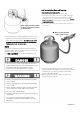
Prueba para detectar fugas de las válvulas, las mangueras y el regulador Sostenga la tuerca de unión y el regulador, como se ilustra, para conectarlos bien a la válvula del tanque. 6. Gire la tuerca de unión en el sentido de las agujas del reloj, apretándola hasta que no se mueva más. El regulador formará un sello en el dispositivo de seguridad de la válvula del tanque, lo que creará cierta resistencia.
ADVERTENCIA Para usar su parrilla en forma segura y para evitar lesiones graves: • No deje que los niños usen la parrilla ni que jueguen cerca de la misma. • Mantenga el área de la parrilla limpia y sin materiales combustibles. • No obstruya los agujeros laterales ni los de la parte posterior de la parrilla. • Revise periódicamente las llamas del quemador. • Use la parrilla sólo en lugares bien ventilados.
ADVERTENCIA Gire los controles y la fuente de gas o OFF tanque cuando no esté en uso. CAUTION Si NO se enciende en 5 segundos, gire los controles del quemador a la posición de APAGADO (OFF), espere 5 minutos y repita el proceso de encendido. Si el quemador no se enciende con la válvula abierta, el gas continuará saliendo por el mismo y puede encenderse accidentalmente, con el riesgo de ocasionar lesiones. Iluminación del partido ▲No se incline sobre la parrilla mientras la enciende. 1.
CAUTION ¡ALERTA CONTRA IMPORTANT: Asegúrese siempre de que los tubos venturi estén limpios.Un tubo de venturi del quemador tiene un área estrecha en la que las arañas tienden a construir nidos. Cómo limpiar la unidad del quemador Siga estas instrucciones para limpiar o cambiar piezas de la unidad del quemador, o si tiene problemas para encender la parrilla. 1. Cierre el paso de gas en las perillas de control y desde el tanque de gas. 2. Retire las parrillas de cocción y Termodisipador. 3.
Cocción indirecta Las aves y los cortes grandes de carne se cocinan lentamente a la perfección en la parrilla por calor indirecto. El calor de los quemadores elegidos circula suavemente por la parrilla, cociendo la carne y las aves sin contacto directo con la llama. Este método disminuye considerablemente los fogonazos al cocer cortes de carne con mucha grasa, debido a que no hay llama directa que incendie la grasa y los jugos durante la cocción. during cooking.
LISTA DE PIEZAS Clave Descripción Key Qty Description 11 2Parrilla de calentamiento 1 2 2 Cocina la parrilla 3 1 43 1Difusor de calor 54 1Bandeja de grasa 2 6 75 1Parrilla del quemador lateral 8 1 6 Estante lateral derecho 9 1 10 1 7 Base del quemador lateral 11 1 8 Quemador lateral 12 1 9 Tapa del quemador lateral 13 1 14 1 10 Gire el eje de la tapa del 15 1 quemador lateral 11 Ingiter cable, quemador lateral 16 1 17 2 12 Fascia, estante de la derecha 18 2 13 Bisel de la perilla de control, 19 1 quemador
LISTA DE PIEZAS ClaveQty Description Descripción Key 147 2Pasador de chaveta 1 2 48 3 449 550 6 51 7 852 9 53 10 54 11 12 55 13 56 14 15 57 16 58 17 1859 19 60 20 21 61 22 23 62 24 25 63 26 64 27 65 28 2966 3067 31 68 32 33 34 35 36 37 38 39 40 41 Quemador principal 1 1Alambre de Ingitor A 1Alambre de Ingitor B 2 Colector, quemador principal 1 1Válvula de gas, quemador principal 1 Regulador 1 1Manguera del quemador 1Válvula de gas, quemador 1lateral 1Panel de control 1Bisel de la perilla de control, 1q
DIAGRAMA PARTS LIST 32 146.
ANTES DE LA ASAMBLEA LEA Y SIGA LAS INSTRUCCIONES A CONTINUACIÓN PARA DESCOMPRIMIR CORRECTAMENTE LAS PIEZAS DE LA PARRILLA DE CAJA. Paso 1: Una vez que se abre la parte superior de la caja de envío, corte hacia abajo sus cuatro bordes con un cúter. Sacar el paquete de Hardware, manual, inferior derecha estante y tanque protector de calor de arriba, también saca dejó estante gabinete de lado. A continuación, quite el soporte de la puerta, riel trasero y el panel posterior del frente.
ANTES DE LA ASAMBLEA Paso 2: Seguir quitar el panel izquierdo del panel izquierdo del gabinete, derecho de la puerta derecha del armario, derecho, dejado la puerta, barra de empuje con ganchos y manijas de la puerta de arriba. A continuación, retire el estante inferior izquierda, dejó el panel y el panel derecho de gabinete principal, parte posterior y frontal inferior soportan barras y parrilla. Retire todas las piezas de bolsas de plástico. 146.
ANTES DE LA ASAMBLEA Paso 3: Quite el panel de la derecha de los principales soportes de la puerta del gabinete, de gabinetes de izquierda y derecho, dejado el panel del gabinete principal y puertas de gabinete principal de espalda. Con la ayuda de un asistente, voltee la cabeza de la parrilla en su lado como se muestra en la figura segunda y retire la pieza superior de espuma de poliestireno. 66 • 146.
ANTES DE LA ASAMBLEA Paso 4: Con la ayuda de un asistente, levante la cabeza de la parrilla de la pieza de espuma de poliestireno de la parte inferior. Coloque en posición vertical sobre la otra pieza de espuma de poliestireno como se muestra en la primera figura. Abra la tapa de la parrilla y sacar las pequeñas cajas embaladas dentro de la cabeza de la parrilla. Retire todos los materiales de embalaje y saque todos los componentes de las cajas. 146.
ASAMBLEA POR FAVOR LEA Y SIGA LAS INSTRUCCIONES CUIDADOSAMENTE PASO A PASO.
Estante inferior Retire el soporte del depósito de estante inferior con el orificio del tanque. Invierta dos estantes inferiores. Alinee y conectarlos con (5) tornillos de M6x13 y tuercas M6 como se muestra. Apriete bien. Tornillos de M6X13 Tuercas M6 Cant: 5 us Cant: 5 us 146.
Estante inferior( continuó) IMPORTANTE: Verifique la posición de todas las partes en este paso antes de insertar y apretar los tornillos. Insertar las barras de soporte de estante dos inferior a través de losν orificios cuadrados en medio del estante inferior como se muestra. Nota: Inserte la barra de apoyo con los recortes cuadrados en la parte posterior del estante inferior. Alinee los orificios de tornillo de barras con los agujeros en el estante inferior.
1 2 Ruedas Vuelta estante inferior boca abajo. Fije las ruedas al estante inferior con (16) tornillos de M6x13. IMPORTANTE: Instale cada rueda en la posición correcta como se muestra en la figura siguiente. Vuelta estante derecho hacia arriba. Coloque los imanes de la puerta principal al estante con (2) tornillos de M4x10. Tornillos de M6X13 Tornillos de M4X10 Cant : 16 us Cant : 2 us Rueda giratoria Rueda giratoria con freno 146.
1 2 Soporte del tanque Inserte los extremos del soporte de tanque en los agujeros en el estante inferior como se muestra. Voltee el estante y utilice (2) pasador de chaveta para asegurar los extremos debajo del estante. Pasador de chaveta Cant: 2 us 72 • 146.
Parrilla carro principal gabinete Para fijar los paneles laterales gabinete principal, alinee los agujeros de la parte inferior de panel con agujeros en el estante inferior. Panel lateral derecho tiene un agujero cuadrado de corte como se muestra. Fije los paneles izquierdos y derecho para estante inferior con (4) tornillos de M6x13. Fije el panel posterior al fondo estante y los paneles laterales con (6) tornillos de M4x10. Tornillos de M6X13 Cant :4 us Tornillos de M4X10 Cant: 6 us 146.
Parrilla carro principal gabinete( continuó) Ate la deflectora barra tanque hacia atrás estante panel e inferior con (2) tornillos de M4x10. Alinee los agujeros en las barras de ángulo de soporte de carro con agujeros en los paneles de estante y el lado inferior. Fije las barras de ángulo con (8) tornillos de M4x10. Tornillos de M4X10 74 • 146.
Parrilla carro gabinete izquierdo Conecte el panel trasero de la izquierda del armario estante inferior y principal panel izquierdo del gabinete con los (5) tornillos de M4x10. Nota: El panel trasero del gabinete izquierdo tiene dos orificios en medio. Ajuste nuevo borde de panel exterior del gabinete izquierdo sobre el panel trasero del gabinete izquierdo. Fije el panel exterior del gabinete izquierdo para estante inferior y la izquierda trasera gabinete con los (6) tornillos de M4x10.
9 Parrilla carro gabinete derecho Conecte el panel trasero del gabinete derecho estante inferior y principal panel derecho del gabinete con los (5) tornillos de M4x10. Ajuste nuevo borde de panel exterior derecho del gabinete sobre la parte trasera derecha del gabinete. Fije el panel exterior derecho del gabinete a estante inferior y trasera derecha del gabinete con (6) tornillos de M4x10.
Soportes de la puerta Inserte el soporte principal de la puerta en su lugar entre los paneles laterales gabinete principal como se muestra. Nota: Asegúrese de colocar el soporte con imanes en la parte inferior. Use (2) tornillos de M4x10 para sujetar el extremo de la bisagra del soporte izquierdo de la puerta izquierda panel exterior del gabinete. Utilice (2) tornillos de M4x10 para sujetar el extremo de imán de soporte a través del panel νgabinete principal en el soporte de la puerta principal.
Magnets de puerta de gabinete lateral Fije dejó imanes de la puerta gabinete al panel lateral gabinete principal con (2) tornillos de M4x10. Fije los imanes de la derecha de la puerta al panel lateral gabinete principal con (2) tornillos de M4x10. Tornillos de M4X10 78 • 146.
Módulos de ignición Fije la caja de módulo de encendido izquierdo al panel izquierdo del gabinete principal con (4) tornillos de M4x10. También una clip de alambre de ignición al panel con (1) tornillo M4x10 como se muestra. Fije la caja de módulo de encendido derecho al panel derecho del gabinete principal con (4) tornillos de M4x10. También una clip de alambre de ignición al panel con (1) tornillo de M4x10 como se muestra. Tornillos de M4X10 Cant :10 us 146.
13 Panel de aislamiento de calor Fije el panel de aislamiento de calor a puerta soporte y lado derecho del panel con los (5) tornillos de M4x10. Fije el soporte del panel de aislamiento térmico para el panel del aislamiento de calor y nuevo panel con (2) tornillos de M4x10 como se muestra. Tornillos de M4X10 Cant: 7 us 80 • 146.
13 Cabeza al carro de la parrilla Este paso requiere dos personas levantar y colocar la cabeza de la parrilla en el carro. Si no lo ha hecho, retire abrazaderas de sujeción de la manguera del regulador y los cables de encendido en la parte inferior de la cabeza de la parrilla. Tire de la manguera al lado del gabinete principal. Cuidadosamente baje la cabeza de la parrilla en el carro. Asegúrese de que la manguera del regulador se cuelga fuera de la principal gabinete y en el gabinete de derecho.
Estante del lado izquierdo Coloque la repisa lateral izquierdo en la parte superior izquierda del gabinete como se muestra en A. Fije la repisa de la parrilla con (2) tornillos de M6x13 y M6 arandelas de compresión del interior de la cámara de combustión como se muestra B. Fije la repisa a la izquierda del gabinete con (4) tornillos de M4x10 como se muestra C. 13 A Tornillos de M6x13 Cant: 2 us Tornillos de M4X10 Cant: 4 us M6 arandelas de compresión Cant: 2 us B C 82 • 146.
Cajón Fije las barras de deslizamiento a los lados del cajón con (4) tornillos de M4x8 y tuercas M4 como se muestra A. Instale cajón frontal con (7) tornillos de M4x10 como se muestra B. Tire de las dos guías gabinete (C) hacia afuera. Insertar barras de laterales de cajón en el gabinete Deslice las barras y empuje el cajón completamente en. 13 Tornillos de M4X8 Cant : 4 us Tuercas M4 Tornillos de M4X10 Cant : 7 us Cant: 4 us A B C 146.
Cajón (continuó) Si el panel frontal del cajón no está perfectamente alineada con el gabinete, el cajón desmontable y ajustado. Para retirar, deslice el cajón completamente. Empuje hacia abajo el pasador del lado izquierdo cajón deslizante y tire hacia arriba el pasador del lado derecho cajón deslizante. Abra el cajón libre de diapositivas gabinete. Véase A. Para ajustar la alineación vertical, afloje la parte delantera o trasera cajón Deslice los sujetadores.
13 Barra de empuje Una barra de empuje al panel de la izquierda con (4) tornillos de M6x17 como se muestra. Nota: Los extremos de gancho deben estar lejos de la parrilla. Tornillos de M6X17 Cant: 4 us 146.
13 Estante de la derecha Fije la placa protectora de estante del lado derecho al estante de la derecha con (2) tornillos de M5x10 y arandelas planas M5 como se muestra A. Coloque la repisa lateral derecho en la parte superior derecha del gabinete como se muestra B. Fije la repisa de la parrilla con (2) tornillos de M6x13 y arandelas de compresión M6 del interior de la cámara de combustión como se muestra C.
13 Estante de la derecha(continuó) Estante de adjuntar a la derecha del gabinete con (6) tornillos de M4x10 como se muestra A. Conectar derecha fascia de estante al panel de control con el (1) tornillo de M4x10 como se muestra B. A Tornillos de M4x10 Cant: 7 us B 146.
13 Estante lateral plegable Conecte los dos plegable lateral soportes para el panel externo de derecho con (4) tornillos de M6x17. Coloque el soporte como figura un show, asegúrese de que el tornillo de M6x12 son tornillos en los orificios inferiores de los soportes de apoyo. Alinee las ranuras de soportes con orificios superiores en los soportes como se muestra estante B. Sostenga en su lugar mientras instalar estante sobre los soportes con (2) tornillos de M6x12.
13 Quemador lateral Afloje quemador lateral en estante lateral destornillando y quitando los dos tornillos delanteros sosteniendo el quemador en su lugar. Véase A. Nota: No afloje el tornillo de electrodo. Línea de tierra negra de quemador lateral tiene dos alambres en una punta del conector.Ejecución cable más largo a través del orificio de ventilación por encima del módulo de encendido en el panel lateral del gabinete derecho.
13 90 • 146.23681310 Cables para el módulo de ignición derecho Conecte los tres cables negros con las puntas pequeñas en tres de cuatro zócalos pequeñas como se muestra, conecte el cable de encendido del quemador lateral naranja con punta pequeña restante pequeño zócalo. Ver figura B. Conecte la punta de cable naranja en la naranja toma gran marcada como se muestra. Ver figura C. Conecte la punta doble cable en la toma de grande restante como se muestra. Ver figura D.
13 Cables para la izquierda del módulo de encendido Conecte los tres cables con los pequeños consejos en tres de las cuatro tomas pequeñas como se muestra. Conecte la punta pequeña de doble cable naranja al pequeño enchufe restantes como se muestra. Conecte la punta grande de doble cable naranja en la naranja toma gran marcada como se muestra. Conecte la punta de cable negro en la toma de grande restante como se muestra.
13 Puertas principales de parrilla para el gabinete Retire los (4) tornillos de M5x15 pre-ensamblados para extremos de las manijas de la puerta principal y utilizarlos para fijar las manijas para puertas como se muestra. Para cada puerta, inserte el pasador de la bisagra inferior en el orificio en el estante inferior del carro (A).
Puertas de gabinete Retire los (4) tornillos de M5x15 pre-ensamblados en los extremos de las manijas de puerta y utilizarlos para fijar las manijas para puertas. Sujete el gancho de la herramienta en la parte posterior izquierda de la puerta con (3) tornillos de M4x10. Para cada puerta, inserte el pasador de la bisagra inferior en el orificio en la parte inferior delantera del carro.
13 94 • 146.23681310 Bandeja de grasa, difusores de calor, parrillas de cocción y calentamiento de Rack Deslice la bandeja de grasa en la parte inferior de la cámara de combustión desde atrás. Asegúrese de que el agujero de drenaje de grasa es en el lado derecho, visto desde la parte trasera de la parrilla. Coloque difusores de calor sobre los quemadores principales. Los difusores de calor entra en la cámara de combustión en cualquier dirección.
13 Taza de la grasa y titular del partido Coloque la taza de la grasa en el clip de taza de grasa. Colgar clip de taza de grasa de la parte inferior de la bandeja de grasa como se muestra. Inserte la abrazadera de la torcedura de nylon en el orificio en la parte trasera del panel del lado izquierdo del gabinete principal como se muestra. Utilizar para fijar el titular del partido a la parrilla. 146.
13 96 • 146.23681310 El tanque LP Alimente la manguera del regulador a través del orificio en el panel lateral νderecho. Tanque de gas LP se vende por separado. Use solamente con una OPD (dispositivo de protección de sobrellenado) había equipado con tanque de gas LP. Llene y verificación antes de colocar en la parrilla y regulador de fugas. Coloque el tanque en el orificio en el estante inferior con la apertura del collar del tanque hacia la derecha como se muestra.
EMERGENCIAS: Si no se puede detener una fuga de gas, o si ocurre un incendio debido a una fuga de gas, llame a los bomberos. Emergencias Fuga de gas de mangueras quebradas, cortadas o quemadas. Causas probables • Manguera dañada. Medidas de prevención / solución • Cierre el gas en el cilindro o en la fuente de los sistemas de gas natural. Si tiene todo tipo de desperfectos, pero no está quemada, cambie la válvula/la manguera/ el regulador.
Resolucion de problemas (continuacion) Problema El quemador o los quemadores no se enciende(n) al usar el encendedor. Pro Causas probables • El cable o el electrodo está cubierto con restos de comida. • Los cables están flojos o desconectados. • Los cables producen cortocircuitos (chispas) entre el encendedor y el electrodo. BOTÓN PULSADOR PIEZOELÉCTRICO Y GIRATORIO: • El botón pulsador se pega en el fondo. • La perilla giratoria gira sin hacer clic. • Hay chispas entre el encendedor y el electrodo.
Resolución de problemas – Encendido electrónico Problema (encendido) SECCIÓN I No aparecen chispas en ningún electrodo cuando se pulsa el botón de encendido; no se oye ningún sonido del módulo de chispas. SECCIÓN II No aparece ninguna chispa en lo electrodos cuando se pulsa el interruptor de encendido; no se oye ningún sonido Medidas de prevención / solución Causas probables Procedimiento de revisión Causas probables • La pila no está instalada adecuadamente. • Revise la orientación de la pila.
Get it fixed, at your home or ours! Your Home For troubleshooting, product manuals and expert advice: www.managemylife.com For repair – in your home – of all major brand appliances, lawn and garden equipment, or heating and cooling systems, no matter who made it, no matter who sold it! For the replacement parts, accessories and owner’s manuals that you need to do-it-yourself. For Sears professional installation of home appliances and items like garage door openers and water heaters.