R REFRIGERATOR SERVICE MANUAL CAUTION BEFORE SERVICING THE UNIT, READ THE SAFETY PRECAUTIONS IN THIS MANUAL. Model #s: 795.77562600 795.77569600 795.77564600 795.77563600 795.77572600 795.77579600 795.77573600 P/No. 3828JL8091A (Last Revision: March. 28.
CONTENTS Safety Precautions 1. Specification ......................................................................................................................................................................... 2. Parts Identification ............................................................................................................................................................... 3. Operation ....................................................................................................
1. SPECIFICATIONS 1-1 DISCONNECT POWER CORD BEFORE SERVICING IMPORTANT – RECONNECT ALL GROUNDING DEVICES 1-7 REPLACEMENT PARTS Relay..............................................................6748C-0004D Overload ........................................................6750C-0004R Defrost Thermostat........................................6615JB2005H Defrost Heater ...............................................5300JK1005D Evaporator Fan Motor....................................
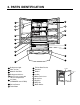
2.
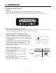
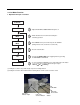
3. OPERATION 3-1. Explanation Of Each Function 1. Function (1) When the appliance is plugged in, it is set to 37 °F for the refrigerator and 0 °F for the freezer. You can adjust the refrigerator and the freezer control temperature by pressing the ADJUST button. (2) When the power is initially applied or restored after a power failure, maintains its previously set temperature. Refrigerator Ultra lce Filter Reset .
5. Ice Plus Selection Please select this function for quick freezing. (1) The ICE PLUS option starts counting its 24-hours period every time the button is pressed. (2) The ICE PLUS function automatically turns off after twenty-four hours pass. 6. Dispenser Use Selection You can select water or ice.
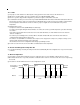
11. Ice Plus (1) The purpose of this function is to intensify the cooling speed of freezer and to increase the amount of ice. (2) Whenever selection switch is pressed, selection/release, the LED will turn ON or OFF. (3) If there is a power outage and the refrigerator is powered on again, Ice Plus will be canceled. (4) To activate this function, press the Ice Plus key and the LED will turn ON. This function will remain activated for 24 hours. The first three hours the compressor and Freezer Fan will be ON.
14. Defrosting (removing frost) (1) Defrosting starts each time the COMPRESSOR running time reaches 7 hours. (2) For initial power on or for restoring power, defrosting starts when the compressor running time reaches 4 hours. (3) Defrosting stops if the sensor temperature reaches 46.4°F (8°C) or more. If the sensor doesn’t reach 46.4°F (8°C) in 2 hours, the defrost mode is malfunctioning. (Refer to the defect diagnosis function, 15.
3-2. Ice Maker Function 1. Operation Principle of icemaker Power On Start Position • Adjusts EJECTOR to Start Position with power on. Icemaking Mode • Waits until water becomes ICE after starting the icemaking operation. Harvest Mode • Runs MOTOR to drop ice from the tray into the ICE BIN. (During harvest mode, check if the ice bin is full.) Park Position • Reaches Start Position Fill • Performs Ice Making Mode after supplying water by operating the SOLENOID in ICE VALVE.
2. Icemaking Mode (1) Icemaking refers to the freezing of supplied water in the ice tray. Complete freezing is assured by measuring the temperature of the tray with Icemaking SENSOR. (2) Icemaking starts after completion of the water fill operation. (3) The icemaking function is completed when the sensor reaches 1 9 °∆F (-7 °∆C), 55 minutes after starting. NOTE : After the icemaker power is ON, the icemaker heater will be on for test for 6 seconds. 3.
5. Function TEST (1) This is a forced operation for test, service, cleaning, etc. It is operated by pressing and holding the cube size button for 3 seconds. (2) The test works only in the Icemaking Mode. It cannot be entered from the Harvest or Fill mode. (3) Caution! Caution! Caution! Caution! If the test is performed before water in the icemaker is frozen, the ejector will pass through the water.
4.
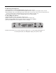
5. ADJUSTMENT 5-1. Compressor 1. Role The compressor intakes low temperature and low pressure gas from the evaporator of the refrigerator and compresses this gas to high-temperature and high-pressure gas. It then delivers the gas to the condenser. 2. Composition The compressor includes overload protection. The PTC starter and OLP (overload protector) are attached to the outside of the compressor.
4. diagnosis 1 Power Source. YES Remove PTC-Starter from Compressor and measure voltage between Terminal C of Compressor and Terminal 5 or 6 of PTC. (Rated Voltage ±10%)? No Voltage. OLP disconnected? 2 YES NO Replace OLP. 5 Check connection condition. Reconnect. Applied voltage isn't in acceptable range. (115V ±10%) Check resistance of Motor Compressor. Check resistance between M-C, S-C and M-S in Motor Compressor. 3 Check resistance of PTC-Starter.
5-2. Positive Temperature Coefficient (PTC) – Starter 1. Composition (1) PTC (Positive Temperature Coefficient) is a no-contact semiconductor starting device which uses ceramic material consisting of BaTiO3. (2) The higher the temperature is, the higher the resistance value. These features are used as a starting device for the motor. 2. Role (1) The PTC is attached to the sealed compressor and is used for starting the compressor motor. (2) The compressor is a single-phase induction motor.
5-3. Over Load Protector (OLP) 1. Define (1) The OLP (OVERLOAD PROTECTOR) is attached to the Compressor and protects the motor by opening the circuit to the motor if the temperature rises and activating the bimetal spring in the OLP. (2) When high current flows to the compressor motor, the Bimetal works by heating the heater inside the OLP, and the OLP protects the Motor by cutting off the current flowing to the Compressor Motor. (OVERLOAD PROTECTOR cross section) 2.
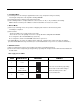
6. TROUBLESHOOTING 6-1. Error Code Summary wWARNING : When you check the Resistance values, be sure to turn off the power. And wait for the voltage-discharge sufficiently. Error Display NO 1 Error Detection Category Freezer Temperature Ref.
6-2. Troubleshooting With Error Freezer Sensor Err or Disconnect CON6 and measure No the value. Is resistance value between pins 11 & 12 of CON6 as below? (BL to BL) Is Er-FS dis played? pin11 Yes Is the connection loose? Yes pin12 Reconnect Test Point Result pin11 to pin12 1.4 ~ 120k‰ No No Reconnect CON6 and Power ON Power Off Tip : To protection of MICOM If the ER-FS appears, Replace the main PCB.
Refrigerator Sensor Error Wiring dia gram Disconnect CON6 and measure No the value. Is resistance value between pins 9 & 10 of CON6 as below? (WH to WH) Is Er-rS displayed? pin9 pin10 Yes Is the connection loose? Yes Reconnect Tpin10 pin9 Result pin9 to pin10 6 ~ 300 k‰ No No Reconnect CON6 and Power ON Power Off Tip : To protection of MICOM If the ER-rS appears, Replace the main PCB.
Defrost Sensor Error D-Sensor CON6 Main PCB 7 8 BO BO 6 1 7 2 BO BO Housing-A Wiring dia gram Is resistance value between pins 1 & 2 of Housing- A as below? (BO to BO) Is Er-dS displayed? Yes Is the connection loose? Yes pin2 pin1 Reconnect Checking Open or Short of wire Test Point Result Pin1 To pin2 1.156 ~141.5k‰ Yes No Reconnect and Power ON Power Off Tip : To protection of MICOM Disconnect CON6 and measure No the value.
Icing Room Sensor Error Icing-Sensor CON101 Display PCB 1 2 BL BL 1 1 2 2 BL BL Housing-A Wiring diagram Is Er-IS displayed? Is resistance value between pins 1 & 2 of Housing- A as below? (BL to BL) Yes Is the connection loose? Display PCB Yes Reconnect pin1 BL pin2 BL Inner of Icing door Checking Open or Short of wire Test Point (1) To (2) No 1.4 ~120k‰ Yes Disconnect CON101 and measure the value.
Defrost Heater Error D-Sensor BO BO 1 6 2 7 BO BO Housing-A 7 8 10 Main PCB CON6 4 WH 1 7 2 BL 1 CON3 BL 6 BN FUSE-M BK DEF-Heater 2 Wiring dia gram 3 BK Enter the TEST 3 MODE Is the voltage value between pins 10 (WH) and 4 (BL) of CON3 115 V AC? Is Er-dH displayed? Yes Yes Replace MAIN PCB No Replace MAIN PWB pin10 WH pin4 BL Is the connec tion loose? Yes Reconnect Relay operation Test Point Result pin4 To pin 10 115V Yes Reset TEST3 MODE(Normal) Is the voltage value
Is the resistance value between pins 10(WH) And 4(BL) of CON3 like as below? Yes Normal Is the resistance value of heater like as below? Replace Heater No pin10 WH pin4 BL Resistance Test Point Ressult (1) To (2) 34 ~ 42 Ω (1) (2) Heater Resistance Test Point Ressult (1) To (2) 34 ~ 42 Ω No Is the connection loose? Yes Yes Reconnect Is the resistance value of DEF-sensor like as below? It depends on the temperature.
Freezer Fan Error 1 Main PCB 2 3 BK WH BK PR CON4 1 1 2 2 3 3 RD F-FAN PR Housing Wiring diagram Is Er-FF displayed? Does the cold-air come out of the top of the main duct? No Check fan motor (Connector, Frozen,Locked) No Replace Main PCB Yes Is the connection loose? Yes Reconnect Yes Is the feedback voltage between pin2 and pin3 of CON4 like as below? (from motor to main board) No Reset and No Enter the TEST 1 MODE Is the output voltage between pin1 and pin2 of CON4 like as below
Condenser Fan Error CON4 7 Main PWB 8 9 SB 1 1 BO 2 2 GN 3 3 BK RD C-FAN PR Housing Wiring diagram Is Er-CF displayed? Is the condenser fan rotate? No Check fan motor (Connector, Locked,mouse) Yes Is the connection loose? Yes Reconnect Yes Is the feedback voltage between pin8and pin9 of CON4 like as below? (from motor to main board) No Reset and Enter the TEST 1 MODE Is the output voltage between pin7 and pin8 of CON4 like as below? Pin7 SB No Replace Main PCB Pin8 BO Pin8 BO Pin9
Icing Room Fan Error 4 Main PWB 5 6 BK RD 4 4 BL 5 5 BN 6 6 RD Icing FAN PR Housing Wiring diagram CON4 Is Er-IF displayed? Does the cold-air come out of the side duct? N0 Check fan motor (Connector, Frozen,Locked) Yes Is the connection loose? Yes Reconnect Yes Is the feedback voltage between pin5 and pin6 of CON4 like as below? (from motor to main board) N0 Reset and Enter the TEST 1 MODE Is the output voltage between pin4 and pin5 of CON4 like as below? Pin4 RD N0 Replace Main
Communication Error CON5 Hinge RD(Rx) 4 MAIN PCB 4 4 3 3 BN(Tx) 3 BO(GND) 2 1 2 WH/BK(12V) CON101 RD(Tx) 3 BN(Rx) BO(GND) 2 WH/BK(12V) 1 1 4 DISPLAY PCB 5 6 * Rx: Receiver Tx: Transmitter Wiring diagram Is Er-CO displayed? Display PCB Is the voltage between pin3 and pin5 of CON101 0 V or 5 V? No Replace Display PCB No Reconnect Yes Display PCB Is the connection loose? Yes Pin5 BO Reconnect Pin3 RD Transmitter Voltages No Display PCB Is the voltage between pins 4 and pin 5 o
Main PCB Is the connection loose? Yes Main PCB Is the voltage between pin2 and pin4 of CON5 0 V or 5 V? Reconnect pin2 BO pin4 RD No Main PCB Is the voltage between pins 2 and pin 3 of CON5 0V or 5V? No Replace the Main PCB Transmitter Voltages Test Point Ressult (1) to (2) 0 V or 5 V Yes pin2 BO pin3 BN After plug in, If Er-CO is disappeared, Explain to the customer! Receiver Voltages Test Point Ressult pin2 to pin3 0 V or 5 V Yes - 28 - No Replace Main PCB
6-3.
In CUBE Mode, Is the voltage between pin5 of CON2 and pin3 of CON3 like as below, while pushing the lever switch? Replace Dispenser PCB No Is the resistance value between (1) and (2) of the Auger motor like as below? Replace Auger Motor No CON2 Pin5 SB (1 )(2 ) CON3 Pin3 WH Resistance of Auger Motor Output voltage of auger motor Level switch Test Point Result Pushing pin5 to pin3 115 V Normal pin5 to pin3 0~2V No Result (1) To (2) 2.38 ~ 4.
Is the resistance between (1) and (2) of the Dispenser Replace No Dispenser Solenoid solenoid like as below? (1) (2) Resistance of Dispenser solenoid Level switch (1) to (2) Result 44 ~54 ½ Yes Is the condition of the micro switch like as Replace No Micro Switch below? (1) (2) Status Tester Normal Infinity Push the Lever 0 ½ Yes After plug in, explain to the customer! - 31 -
Crush Mode Doesn't work CON2 5 SB 7 Dispenser PCB Lever S/W 3 CON3 WH 4 1 1 2 V Auger Motor S Solenoid Dispenser Housing-B RD 9 1 BL 2 1 2 Wiring diagram Display PCB Is the connection loose? Yes In Crush Mode, Is the voltage between pin5 of CON2 and pin3 of CON3 like as below, while pushing the lever switch? Reconnect No Replace Dispenser PCB CON2 Pin5 SB CON3 Pin3 WH No Output voltage of Auger motor Level switch Test Point Result Pushing pin5 to pin3 115 V Normal pin5 t
In CUBE Mode, Is the voltage between pin7 of CON2 and pin9 of CON3 like as below, while pushing the lever switch? Replace Dispenser PCB No Is the voltage between (1) and (2) of the Dispenser solenoid like as below? Replace Dispenser Solenoid No CON2 Pin7 BL (1) (2) CON2 Pin9 RD Resistance of Dispenser solenoid Output voltage of auger motor Level switch Test Point Result Pushing pin7 to pin9 115 V Normal pin7 to pin9 0V Test Point Result (1) To (2) 44 ~ 54 Ω Yes Is the condition of the
Crush Mode Doesn't work Lever S/W BL 1 7 Dispenser PCB 1 PR 2 2 V Door Water Valve V Machine Room Water Valve Housing-A CON2 BL 6 4 Main PCB 1 11 GN 1 6 1 Housing-B CON3 Wiring diagram Display PCB Is the connection loose? Yes In Water Mode, Is the voltage between pin1 and pin7 of CON2 in dispenser PCB like as below, while pushing the level switch? Reconnect No Replace Dispenser PCB Dispenser PCB CON2 Pin7 BL Dispenser PCB CON2 Pin1 PR Output voltage of door water valve No
In Water Mode, Is the voltage between pin4 and pin11 of CON3 in main PCB like as below, while pushing the level switch? Second Water- valve Is the resistance value of Second-water valve like as below? Replace Main PCB No Replace Second Water-valve No (1) Main PCB CON3 Pin11 GN (2) Pin4 BL In door Dispenser Output voltage of machine room water valve Ice Maker Checking resistance of Second-valve Test Point Result Test Point Result pin4 to pin11 115 V (1) to (2) 360 ~ 420 Ω Yes First Water
Freezer-lamp Doesn’t work F-DOOR Switch BO 5 7 Main PCB F-Lamp BL 6 4 SB 1 SB SB 2 Housing CON6 CON3 SB Wiring diagram Is the condition of the freezer door switch like as below? No DC Part Is the voltage between pin 11 No and 12 of CON6 like as below? Replace Door switch Replace Main PCB AC Part Pin5 SB Pin6 SB Voltage of Door switch Test Point Result Door Status Tester Normal 0Ω Push the Switch Infinity pin5 to pin6 5V Open pin5 to pin6 0V Yes Yes Is the connection loose?
Refrigerator-lamp Doesn’t work MAIN PCB PR 10 R-Lamp 4 11 CON3 CON4 4 11 9 BL GY GY GY GY GY 12 Housing GY 1 12 R-DOOR Switch Hinge Wiring diagram Is the condition of the refrigerator door switch like as below? Is the voltage between pin10 No and pin11 of CON4 like as below? Replace Door switch No Replace Main PCB CON4 Pin11 GY Pin10 GY AC Part Voltage of Door switch Test Point Result Door DC Part Status Tester Normal 0Ω Push the Switch Infinity pin10 to pin11 5V Open pi
Poor cooling in the refrigerator compartment MAIN PWB Is the connection loose? Yes Is the voltage between pins 1 and pin 2 of CON4 like as below? Replace No Replace the Main PCB Pin1 WH Pin2 BK CON4 Voltage of F-fan CON3 No Test Point Result pin1 to pin2 12 ~ 16 V Yes Enter the TEST 1 MODE Is the voltage between Pins 4 and pin 12 of CON3 like as below? Yes Reconnect Main PCB Feedback check.
Does the cold-air come out of the top of the main duct? No Check the Damper itself After reset the unit, take steps to PCB as follows for temperature compensation. 1. In the case of 6871JB1431 ( by July 2007) : Compensate with replacing RCR1 Yes Enter the TEST 2 MODE Does not cold-air come out of the top of the main duct? Yes Check the Damper itself RCR1 Temp. Compension Ressult 8.2 k‰ - 0.5 deg Current 5.6 k‰ - 1 deg 3.3 k‰ - 1.5 deg 2 k‰ - 2 deg 470 k‰ - 2.
Over cooling in the refrigerator compartment MAIN PWB Is the connection loose? Yes Enter the TEST 2 MODE Does the cold-air coming out of the top of the main duct.
Enter the TEST 3 MODE Is the voltage between Pins 4 and pin 12 of CON3 like as below? Pin12 BK Pin4 BL Replace Yes Damper After reset the unit, take steps to PCB as follows for temperature compensation. 1. In the case of 6871JB1431 ( by July 2007) : Compensate with replacing RCR1 CON3 RCR1 Temp. Compension Ressult Voltage of Compressor 180 k‰ + 2.5 deg Current Test Point Ressult 56 k‰ + 2 deg pin4 to pin12 115 V 33 k‰ + 1.5 deg 18 k‰ + 1 deg 12 k‰ + 0.
(NOTE) 1. How To Remove Terminal Position Assurance (TPA) 3. How To Start Test Mode Push the TEST button on the Main PWB, You can start the TEST MODE. * AC TPA TEST BUTTON * DC TPA After measure the values, you should put in the TPA again. 2.
4. How to check the Fan-Error (1) 6871JB1431A ( ~ July 2007) After sending a signal to the fan, the MICOM checks the BLDC fan motor’s lock status. If there is no feedback signal from the BLDC fan, the fan motor stops for 10 seconds and then is powered again for 15 seconds. To determine that there is a fan motor malfunction, this process is repeated 5 times. If the fan motor is determined to be defective, the error code will be shown continuously in the display.
7. COMPONENT TESTING INFORMATION 7-1. Defrost Controller Assembly Function - Controller assembly is consist of 2 kinds of part those are fuse-m and sensor. we can decide part is defect or not when we check the resistance. - Fuse-m can cut off the source when defrost heater operate the unusual high temperature. - Sensor give temperature information to Micom How to Measure (Fuse-M) Set a ohmmeter to the 2 housing pin. Measure the 2 pin connected to Fuse-M. If the ohmmeter indicate below 0.
7-2. Sheath Heater Function Sheath heater is a part for defrost. All heating wire is connected to only one line. So we can decide part is defect or not when we check the resistance. How to Measure (1) (2) Set a ohmmeter connect to The 2 housing pin. Measure the 2 pin connected to Sheath Heater.
7-3. Door Heater Assembly Function The heater is designed to prevent the raising dew from door. How to Measure Standard Test Point Ressult (1) to (2) 2.3 ~2.
7-4. Door Switch Function How to Measure The switch sense if the door open or close. - When the door open, lamp on. - When the door open, the switch give information to Micom. When the door open, internal contact operate on and off moving plunger of door switch up and down. Button (Plunger) 1 2 3 3 4 1 4 2 2 Beep 3 1 Beep Check the resistance between connectors 1,2 and 3,4 .It means check whether or not applying an electric current.
7-5. Solenoid Function - Dispenser solenoid : When customer push the dispenser button, Pull duct door and abstract from ice bank.
7-6. AC Motor ASSEMBLY (Geared Motor & Solenoid) Function The Geared Motor of ac motor assembly advances forward the ice by rotating the ice and The solenoid of ac motor assembly selects one of the cube mode or crush mode. - Cube solenoid : Pulling the stir lip for moving the ice in ice maker system. How to Measure < Geared Motor > < Cube Solenoid > 1 Take out the male housing from female housing 1 Remove the female housing from terminal.
7-7. Damper Function The damper supplies the cold air at freezer room to chillroom by using the damper’s plate. Chillroom is colder than before when damper’s plate is open. When damper’s plate is close, chillroom’s temperature will rise. How to Measure 1 Blue < Damper Circuit > 1 Blue 2 Red 3 White 3 White Checj the 1 , 3 4 Tellow extension Check the 2 , 4 Check the 1 , 3 Check the resistance between connectors 1,3 and 2,4 .It means check whether or not applying an electric current.
7-8. Lamp Socket Function The lamp socket connect cover lamp assembly to lamp. The lamp socket fix lamp and unite lamp and cover lamp assembly. The lamp socket supply electric source to lamp also. How to Measure (1) (2) (3) (4) Check the resistance between connector of housing and connector of lamp socket. It means check whether or not applying an electric current. If there is resistance it means the lamp socket is not inferiority.
7-9.
8. DISASSEMBLY INSTRUCTIONS 8-1 REMOVING AND REPLACING REFRIGERATOR DOORS ● Removing Refrigerator Door w CAUTION: Before you begin, unplug the refrigerator. Remove food and bins from doors. u Left Door - Figure 2 2. Open the door. Loosen the top hinge cover screw (1). Use a flat tip screwdriver to pry back hooks on front underside of the cover (3). Lift up the cover. 3. Disconnect the door switch wire harness (2). Remove the cover. 4. Pull out the tube. 5. Disconnect the three wire harnesses (5).
● Door 8-2 DOOR ● Door Gasket Removal 1. Remove door frame cover Starting at the top of cover and working down, snap the cover out and away from the door. Gasket Replacement 1. Insert gasket bracket clips 1) Insert the gasket bracket edge beneath the door frame edge. 2) Turn the upper gasket bracket spring so that the spring ends are in the door channel. 3) Push in the clip until you hear it snap securely into place. Frame Cover Gasket Bracket Clip Handle Spring Door Frame Figure 1 2.
2) Press the gasket into the channels on the three remaining sides of door. 8-3 DOOR ALIGNMENT If the space between your doors is uneven, follow the instructions below to align the doors: 1. With one hand, lift up the door you want to raise at the the middle hinge. 2. With the other hand, use pliers to insert the snap ring as shown. 3. Insert additional snap rings until the doors are aligned. (Three snap rings are provided with unit.) Figure 6 3.
* Ice Fan Scroll Assembly Replacement 8-6 LAMP 1) Remove the plastic guide for the slides on left side by unscrewing the phillips head screws. 2) Pull the grille forward as shown in the second picture. 3) Disconnect the wire harness of the grille 4) Remove the scroll assembly by loosening 2 screws (1) (2) (3) (4) Figure 14 8-6-1 Refrigerator Compartment Lamp 1. Unplug the Refrigerator or disconnect power at the circuit breaker. 2. If necessary, remove the top shelf or shelves. 3.
2) Remove display frame assembly by making a gap between the display frame assembly and door with a flat blade screwdriver and pulling it forward. The cover dispenser is attached with a hook. 8-8 MULTI DUCT 1. Remove the upper and lower aps by using a flat screwdriver, and remove 2 screws. (Figure 17) 2. Disconnect the lead wire on the bottom position. Figure 17 8-9 MAIN PWB 1) Loosen the 3 screws on the PCB cover.
8-13 SUB PWB FOR WORKING DISPENSER 8-15 ICE CORNER DOOR REPLACEMENT 1) Loosen the screw on the sub PCB. 1) Loosen the front screw as shown in the picture. 2) Lift up the hinge with one hand. 3) Pull out the Ice Corner Door with the other hand. hinge 2) Pull the sub PCB down. 3) Disconnect the wire harness and replace the sub PCB in the reverse order of removal. 8-16 ICEMAKER ASSEMBLY 1) Loosen two screws as shown in the first picture.
8-17 AUGER MOTOR COVER 1) After removing the icemaker remove the (5) stainless screws holding the auger motor cover, shown in the picutres below. 2) Grip the bottom of the motor cover assembly and pull out it. 3) Disconnect the wire harness of the motor cover assembly. There is a auger motor on the back, as shown in the picture.
8-18 HOW TO REMOVE THE DOOR ICE BIN 8-19 HOW TO INSERT THE DOOR ICE BIN 1) Grip the handles, as shown in the picture. 1) Insert the Ice Bin, slightly tilting it to avoid touching the icemaker. particularly the feeler arm lever. 1 2 2) Lift the lower part slightly. Insert the ice bucket carefully avoid contacing the automatic shut off arm. 3) Take the ice bin out slowly.
8-20 HOW TO REMOVE AND REINSTALL THE PULLOUT DRAWER 8-20-1 Follow Steps to Remove Step 1) Open the freezer door. Step 2) Remove the lower basket. Step 3) Remove the two screws from the guide rails (one from each side). Step 4) Lift the freezer door up to unhook it from the rail support and remove. Pull both rails to full extension. Step 5) First: Remove the gear from the left side first by releasing the tab behind the gear, place a screwdriver between the gear and the tab and pull up on the gear.
8-20-2 Follow Steps to Reinstall Step 1) Reinstall the right side gear into the clip. Step 2) Insert the rail into the right side gear. Gears do not need to be perpendicular to each other. Step 3) Insert the rail into the left side gear, and insert the gear into the clip. Step 4) The rail system will align itself by pushing the rails all the way into the freezer section. Pull the rails back out to full extension. Step 5) Reinstall the freezer door by inserting the rail tabs into the guide rail.
8-21. WATER VALVE DISASSEMBLY METHOD 8-22. FAN AND FAN MOTOR DISASSEMBLY METHOD 1) Turn off the water. Then separate the water line from the valve. 1) Using a short screwdriver, loosen one SCREW in DRAIN PIPE ASSEMBLY and one connected to the MOTOR COVER. MOTOR COVER → 2). Separate the mechanical cover and valve screw. 2) Pull and separate the FAN ASSEMBLY and MOTOR turning counterclockwise based on the MOTOR SHAFT.
8-23 PULL OUT DRAWER To separate the drawer, push the front left and right hooks in direction to pull up and remove. Then gently lift the gear part of rear left and right side of the drawer and pull it out in direction. 1 3 2 To install, reposition the gear part of rear left and right side of the drawer after pulling out both rails as much as possible, and gently push down both left and right side while checking the hook on the front part.
9. PCB ASSEMBLY 9-1.
EBR34917102 (from Aug 2007) CON5 CON6 CON7 CON1 CON2 - 66 - CON4 CON3
9-2.
Get it fixed, at your home or ours! REPAIR PARTS LIST Your Home For repair – in your home – of all major brand appliances, lawn and garden equipment, or heating and cooling systems, no matter who made it, no matter who sold it! The model number of your refrigerator is found on the serial plate inside. MODELS No. 795.77562600 795.77569600 795.77564600 795.77563600 795.77572600 795.77579600 795.77573600 For the replacement parts, accessories and owner’s manuals that you need to do-it-yourself.
CASE PARTS CAUTION: Use the part number to order part, not the position number.
CASE PARTS LOC No.
CASE PARTS LOC No.
FREEZER PARTS CAUTION: Use the part number to order part, not the position number. 250C 250D 145C 250E 250D 145G 250C 136B 145J 131A 145K 145F 145M 145J 145H 237C 136A LOC No.
REFRIGERATOR PARTS CAUTION: Use the part number to order part, not the position number. 141B 141A 141B 141A 141C 141B 141A 141C 141B 140A 141C 141D 140C 140B 167B 154A 140D 151C 151F 151D 154C 151A 151F LOC No.
DOOR PARTS CAUTION: Use the part number to order part, not the position number.
DOOR PARTS LOCNo.
DISPENSER PARTS 278A 278C 402C 278B 275A 278D 276A 405A 500B 501A 276B 279D 279E 279B 280B 280C 281A 279A LOCNo.
ICE MAKER & ICE BANK PARTS 606A 600B 630J 600A 611A 630F 630B 630C 630A 630K 630M 630H 614A 630E 630N 630D 630G 630L LOCNo.