Use & Care Guide Manual de Uso y Cuidado English / Espa_ol Models/Modelos: Items / Arficulos: 148.16156210/148.16157210 640-03838924-3 / 640-03838925-0 I(enmore @ @ @ @ P/N S3218AN-Manual Sears Brands Management Corporation Hoffman Estates, IL 60179 U.S.A. www.kenmore.com www.sears.com www.kmart.
If you smell gas: 1. Shut off gas to the appliance. 2. Extinguish any open flame. 3. Open lid. 4. If odor continues, keep away from the appliance and immediately call your gas supplier or your fire department. 1. Do not store or use gasoline or other flammable liquids or vapors in the vicinity of this or any other appliance. 2. An LP cylinder not connected for use shall not be stored in the vicinity of this or any other appliance.
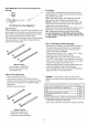
For Sears professiona/ installation of home appliances, garage door openers, water heaters, and other major home items, in the U.S.A. call 1-800-4-MY-HOME® ForYourSafety .................................. GrillService Center ............................... Product Record Information ........................ 2 2 2 Safety Symbols .................................. 2 Installation Safety Precautions ....................... 2 Kenmore GrillWarranty ........................... 3 UseandCare......................
• NEVER store a spare LP cylinder under or near the grill appliance or in an enclosed area. • Never fill a cylinder beyond 80% full. • If the information in the two points above is not followed exactly, a fire causing death or serious injury may occur. • An over filled or improperly stored cylinder is a hazard due to possible gas release from the safety relief valve. This could cause an intense fire with risk of property damage, serious injury or death.
LP Tank Exchange •Many retailers that sell grills offer you the option of replacing your empty LP tank through an exchange service. Use only those reputable exchange companies that inspect, precision fill, test and certify their cylinders. Exchange your tank only for an OPD safety feature-equipped tank as described in the "LP Tank" section of this manual. Connecting Regulator To The LP Tank 1. LP tank must be properly secured onto grill. (Refer to assembly section.) 2.
Leak Testing Valves, Hose and Regulator 1. Turnall grillcontrolknobsto OFF. 2. Be sure regulator is tightly connected to LP tank. . Holdcouplingnut and regulator as shownfor properconnection to LP tankvalve. Completely open LP tank valve by turning OPD hand wheel counterclockwise. If you hear a rushing sound, turn gas off immediately. There is a major leak at the connection. Correct before proceeding by calling Sears for replacement parts at 1-800-4-MY-HOME®. 4.
For Safe Use of Your Grill and to Avoid Serious Injury: • Do not let children operate or play neargrill. • Keep grill area clear and free from materials that burn. • Do not block holes in sides or back of grill. • Check burner flames regularly. • Use grill only in well-ventilated space. NEVER use in enclosedspace such as carport, garage, porch, covered patio, or under an overhead structure of any kind. • Do not use charcoal or ceramic briquets in a gas grill. (Unless briquets are supplied withyour grill.
5.Ifignition doesnotoccurin5seconds, turntheburner control off,wait5 minutes forgastoclearaway,andrepeat thelighting procedure. 6.Tolightotherburners, repeat step4. NOTE: If ignitordoesnotwork,followMatchLighting instructions. Turn controls and gas source or tank OFF when not in use. Burner Flame Check ,Remove cooking grates and heat diffusers. Light burners, rotate knobs from HIGH to LOW. You should see a smaller flame in LOW position than seen on HIGH. Perform burner flame check on sideburner, also.
Donotusecitrisot, abrasive cleaners, degreasers ora concentrated grillcleaner onplasticparts.Damage toand failureofpartscanresult. •Porcelain surfaces:Because ofglass-like composition, most residue canbewipedawaywithbaking soda/water solution or specially formulated cleaner. Usenonabrasive scouring powder forstubborn stains. *Painted surfaces: Wash with mild detergent or nonabrasive cleaner and warm soapy water. Wipe dry with a soft nonabrasive cloth.
VERY IMPORTANT: Burner tubes must reengage valve openings. Food Safety Food safety is a very important part of enjoying the outdoor cooking experience. To keep food safe from harmful bacteria, follow these four basic steps: Clean: Wash hands, utensils, and surfaces with hot soapy water before and after handling raw meat and poultry. Separate: Separate raw meats and poultry from ready-to-eat foods to avoid cross contamination. Use a clean platter and utensils when removing cooked foods.
Gas Requirements LP Gas If your grill is for LP Gas, the regulator supplied is set for an 11-in.water column (WC) and is for use with LP gas only.The factory-supplied regulator and hose must be used with a 20-lb. LP gas tank. Care and MaintenanceTime TableChart Excess Flow Control and Low Heat The propane regulator assembly incorporates an excess flow device designed to supply the grill with sufficient gas flow under normal conditions yet control excess gas flow.
Push the transformer power cord through the opening in the grill cart rear panel as shown, and plug it into an extension cord. To operate light, press the Main Light switch on the control panel to ON or OFF. For your convenience, this grill comes equipped with a UL approved transformerfor outdoor use that provides low voltage to power 10-watt grill light featured with this model.
. Make sure that the Main Light switch on the control 4. Pull out the light bulb and replace with a new bulb. panel is pressed to OFF, and that transformer power Bulb cord is disconnected from power source. . Use a screwdriver to loosen the screw holding the ( (9 lens in place. While loosening the screw, hold the lens in place so that it does not fall and break. Lens .......... . Reverse the instruction from "steps" 3-1for installation. ® ® ,_ ® 3. 1.
Operating Instructions: 1. To connect, push back socket sleeve. Socket Your grill can be converted to natural gas. The conversion must be performed by a qualified gas technician. The following listed Natural Gas Conversion Kit (sold separately) and 1.33 mm nozzle (provided with grill) are required for the conversion. Natural gas conversion kit Kenmore Model # 10478 (Manufacturer Part No.: S3218AN-KIT) Sleeve_ _- Plug 2. Insert plug and release sleeve. 3. Push plug until sleeve snaps forward.
Key Qty Description Manufacturer Part # Key Qty Description Manufacturer Part# 1 1 HOOD HANDLE 3218LT-00-4300 43 1 SWITCH E3520-00-8015 2 2 HANDLE BASE S3218ANR-O0-4001 44 I REAR BURNER BEZEL L3218-90-3902 3 I HOOD S3218ANR-90-4109 45 I REAR BURNER KNOB L3218-06-3901 4 I TEMPERATURE GAUGE 2818-2T-A300 46 1 IGNITION WIRE S3218ANR-O0-8061 5 I WASHER E3518-00-4099 47-1 1 CONTROL BOX (BLACK) S3218ANB-90-3101 6 5 R-PIN GB/T 91-2009 47-2 1 CONTROL BOX (RED) S
@ @ / @ ® ®@@ @ S @ 16 @ @ @ @
UNPACKING After removing all parts and hardware pack from the top of the shipping box, and when the only part showing is the grill head, use a box cutting knife to slice down the sides of the box. Be careful of staples along shipping box edges. Remove the corner supports from the box and the styrofoam side pieces from the grill head. With the aid of an assistant, rest grill head on one of the styrofoam side pieces to protect grease tray.
Attach Rear Panel to Bottom Panel with 4 screws as shown. 1/4-20x 5/8" Screw Qty.4 Rear Panel Bottom Panel Attach side panels to bottom panel as shown. For each side panel, there are three screws for the rear panel and three for the bottom panel. Insert the three bottom panel screws first.. Rear Panel Le_ Panel 1/4-20x 5/8" Screw Qty.
Attach the side panel brackets to the side panels and bottom panel with 3 screws each as shown. Left Panel Bottom Panel 1/4-20x 5/8" Screw Qty. 6 Right Panel Side Panel Bracket Slide the tank ring bracket onto the end of the tank ring as shown. Attach the bracket to the rear panel with 2 screws as shown. Tank Ring Tank Ring Bracket Rear Panel 1/4-20x 5/8" Screw Qty.
Attach front beam to side panels with 2 screws on each side as shown. Left Panel 1/4-20x 5/8" Screw Qty.4 Right Panel Front Beam Remove the cap and the nut from the igniter. Secure the igniter and the igniter protective box to side panel with the nut. Then, reassemble the cap to the igniter.
Attach the drip tray support to the front beam and rear panel with 4 screws as shown. NOTE: Drip tray support tabs connect to outside of front beam. Rear Panel Drip Tray Support 1/4-20x 5/8" Screw Qty.4 Front Beam Slide the drip tray through the rear panel and into the drip tray support as shown.
Install the transformer to the rear panel with 4 each 5/32-32x3/8" screws and nuts. 5/32-32 x 3/8" Screw 5/32 Nut Qty. 4 Qty. 4 f J ./, ./ _J ,,f J. ._ j .s J Install the LP tank exclusion rods, plain end to the bottom panel and nut end to the rear panel. 1/4-20 x 5/8" Screw Qty.
Cut tie wraps holding regulator and side burner valve in place underneath grill head control panel. Be careful not to cut igniterwires or the tie wraps holding the igniter wires in place. With the aid of an assistant, lift and place grill head onto cart. Grill head sides go over attachment tabs on cart. Make sure that side burner valve hangs outside the cart, and that regulator and igniter wires hangs inside the cart.Attach head to cart with 4 screws as shown. 1/4-20x 5/8" Screw Qty.
Side Burner Shelf Loosen the four screws attached in the right panel of the burner box 3 to 4 turns as shown. Hang the side burner shelf by the slotted holes in its side onto the four loosened screws. Open the grill lid and use the 1/4-20x 1-1/4" screw to fasten the side burner shelf from the inside of the burner box as shown. Tighten the four previously loosened screws. Loosen 1/4-20x 1-1/4"Screw Qty. 1 Side Burner Shelf Side Burner Shelf Loosen and remove the two screws holding side burner in place.
Side Burner Tube Align side burner nozzle with side burner tube. Push nozzle onto tube. Secure nozzle to tube with two screws as shown. Replace the two side burner screws removed at the beginning of step 16. Place the side burner drip tray into position as shown. 5/32-32x 3/16" Screw Qty.2 Side Burner Shelf Side Burnerdrip tray Side Burner Nozzle Side Burner Ignition Wire The side burner ignition wire has two connectors. Plug the wider connector into one of the two wider sockets in the igniter.
Side Burner Ignition Pin Wire Run the side burner ignition pin wire into the cart and plug it into one of the narrow sockets in the igniter as shown. Ignition pin wire Connect here Ignition pin wire Other Ignition Wires Plug the six remaining narrow wire connectors into the remaining narrow igniter sockets, and plug the remaining wide connector into the remaining wide igniter socket. Also, connect light wire to transformer as shown on page 12.
For each door, insert bottom hinge pin into hole on bottom panel. Push down on top hinge pin to insert into hole in bottom corner of control panel. Adjust magnets on the bottom panel and front beam to align the magnets with doors, and then tighten magnet screws. Left Door ... Right Door Install the Heat Diffusers, Cooking Grates, Side Burner Grate and Warming Rack Position the heat diffusers, cooking grates, side burner grate and warming rack as shown.
LP Tank Installation Open front doors of cart. Set base of tank into cart with tank collar opening facing to the right as shown. Connect regulator to tank (see page 5 of Use and Care section).
The 10478 NG kit contains orifices for various grill models. Please select the orifices as listed and discard the rest. Follow the conversion instruction providedwith the kit. Model Main burner 1.37mm Side burner 1.37mm Rear burner 1.33mm [ 148.16156210 148.16157210 5 pc Provided in 10478 Kit 1 pc Provided in 10478 Kit ] 1 pc Provided with grill MainBurnerConversion , Remove the R pins at the back of main burners to detach burners from bracket.
Put the new orifice into the orifice removal . tool (B), and then insert the tool into the burner opening and tighten the new orifice into the valve. Repeat this step for all five burners. Make sure you are using the correct orifice, which is marked "1.37". (Fig. 3) Rotate the air shutter opening from the . LP setting to the NG setting. Air shutter opening LP: 1/4" open to adjust I NG: 1/6" to 1/8" open (Fig. 4) Fig. 4 Side Burner Conversion 1. Remove 2 screws (5/32-32x3/16 in.
, Tighten the new orifice to the valve. Make sure you are using the correct orifice, marked "1.37". (Fig. 7) 1.37 ili................................................................................... Fig. 7 Rear Burner Conversion , Remove 5 screws (3/16-24 X 1/2 in.) at the back of burner box to detach the rear burner cover Rear burner cover from the rear panel of burner box. During this process, hold the rear burner cover, otherwise, it will drop and may break, possibly causing injury.(Fig.
, Replace it with the NG orifice, and then tighten. Make sure you are using the correct orifice, marked "1.33". This is the orifice that came with the grill. (Fig. 10} 1.33 Fig. 10 , Loosen the air shutter of the rear burner and adjust the distance between air shutter and rear burner. In LPG model, the air Distance shutter is at its rightmost position, and the distance is about 0.67 inch; and in NG model, the air shutter should be at its leftmost position, and the distance is about 0.4 inch.
Adjust valve control screw , Pull all the knobs off of valve stems. Adjust the screw in the valve hole using the flathead screwdriver. Turn screws two complete turns counterclockwise. (Fig. 13) I / ! Valve hole Fig. 13 2. Press all the knobs back onto valve stems. 3. After all the conversions are complete, return heat diffusers to firebox, followed by the grates and warming rack.
Problem Possible Cause Corrective Action Grill or side burner will not light The ignition wire came off 1. Reconnect the ignition wire to the the electrical igniter. electrical igniter. 2. The distance between the 2. Loosen the ignition pin and adjust the ignition pin and the burner distance, then fasten it again. is greater than 0.1-0.2 inch(side burner). 3. Call customer service for a The ignition wire is broken. replacement ignition wire. 4. The battery has died. 4. Install a new AA battery. 5.
Problem Burner blows out Possible Cause Corrective Action 1. LP tank is empty. 2. Burner is not aligned with the control valve. 3. Gas supply is not sufficient. 1. Low heat is found in natural gas models. Low heat with the knob in "HI" position 1. Refill the LP Tank. 2. Install the burner correctly. . Check the gas supply hose and make sure there are no leaks and no knots. 1. This model is set for 7 in. natural gas usage. Please check your natural gas supply system to have correct gas pressure.
Problem Low heat, LP gas Possible Cause Corrective Action The propane regulator assembly incorporates an excess flow device designed to supply the grill with sufficient gas flow. Rapid changes in pressure can trigger the excess flow device, providing a low flame Please follow these instructions: 1. Make sure all burners are "OFF". 2. Open the tank valve and wait 5 minutes. 3. Light the burner one at a time following the lighting instructions listed on the door liner and low temperature. 1.
Precauciones de seguridad para la instalacion • Utilice Ia parrilIa, como Ia compr6, s61ocon gas LP (propano) y el ensambtede regulador/v_lvutaque se suministra. Deber_ comprar un kit de conversi6n para uso con gas natural. • La instalaci6n de Ia parrilIadebera conformarse con ta normativa local, o en ausencia de esta, con ta Normativa Si detecta olor a gas: 1.¢ierre el gas que va a la unidad. 2. Extinga cualquier llama expuesta. 3.Abra la tapa. 4.
Some limitations and exclusions apply. For prices and additional information call 1-800-827-6655. Sears Installation Service Para su seguridad ................................ 37 Centre de Servicio para ta parrilIa .................... 37 Informaci6n de registro del producto .................. 37 Simbotos de seguridad............................. 37 Precauciones de seguridad para la instataci6n........... 37 Garantia de Ia parrilIa Kenmore ........................ 38 Uso y cuidado ..............
tanque de LP dentro de un vehicuto que pueda recatentarse con el sot. • No guarde un tanque de LP en un area donde jueguen los ni_os. Cilindro de LP • El cilindro de LP utilizado con su parrilla debera cumplir con los siguientes requisitos: • Utilice los cilindros de LP con estas medidas requeridas: 12" (30,5 cm) (diametro) x 18" (45,7 cm) (alto) con 20 lb. (9,1 kg) de capacidad maxima.
Intercambio del tanque LP • Muchosdistribuidoresque venden parrilIasofrecen la opci6nde reemplazarsu tanque vacio de LP a travesde un servicio de intercambio.Utilices61oIas empresasde intercambiocon reputaci6n que inspeccionan,Ilenancon precisi6n,prueban y certificansus cilindros.Intercambie su tanque s61opot un tanque equipado con la caracteristica de seguridad OPD segun se describe en la secci6n "Tanque LP" de este manual. Como conectar el regulador al tanque de LP 1.
Valvulas para prueba de fugas, manguera y regulador 1. Gire todas Ias periIIas de control de Ia parriIIa a la posici6n OFF (cerrado). 2. Cerci6rese de que el regulador este conectado de forma bien ajustada at tanque de LP. Sostengalatuercade empalmey el reguladorcomose ilustrapara laconexionadecuadaa la valvuladel tanquede LP. 3. Abra comptetamente Ia v_lvuta del tanque de LP girando Ia rueda manual OPD en el sentido antihorario. Si escucha un sonido sernejante a una rafaga, cierre el gas inmediatamente.
Consejos practicos sobre seguridad • D Para el uso seguro de su parrilla y para evitar lesiones graves: • No permita que los ni_os hagan funcionar la parrilla ni deje que jueguen cerca de ella. • Conserve el area de la parrilla despejada y sin materiales que pudiesen arder. • No obstruya los agujeros de los costadoso la parte posterior de la parrilla. • Revise las llamas del quemador regularmente. • Utilice la parrilla s61oen un espacio bien ventilado.
5.Sinoenciende en5segundos, apague elcontrol del quemador, espere 5 minutos paraquesedisipeelgasy repitaelprocedimiento deencendido. 6.Paraencender otrosquemadores, repita elpaso4. NOTA: Sielencendedor nofunciona, sigatasinstrucciones deencendido conf6sforos. Revision de la llama del quemador • Retire Ias rejiIIasde cocci6n y los difusores de calor. Encienda los quemadores, gire Ias perilIas de HIGH a LOW. Debe ver una llama m_s pequefia en ta posici6n LOW que Ia que vio en HIGH.
deje secar comptetamente at aire. No aplique limpiador caustico para parrilla/horno a las superficies pintadas. • Partes plasticas: Lave con agua caliente jabonosa y seque. No utiIice Citrisot, Iimpiadores abrasivos, desengrasadores ni un timpiador concentrado para parrilIa en tas partes pDsticas. Pueden ocurrir daSos y fatIa en esas partes.
MUY IMPORTANTE: Los tubos del quemador deberan volverse a enganchar en las aberturas de las valvulas. Seguridad alimentaria La seguridad atimentaria es una parte muy importante de disfrutar Ia experiencia de cocinar at aire Iibre. Para conservar los alimentos protegidos de Ias bacterias nocivas, siga estos cuatro pasos b_sicos: Limpiar: L_vese Ias manos, los utensilios y superficies con agua catiente jabonosa antes y despues de manipular came o aves crudas.
quemadores en la posici6n HI durante 15 minutos para realizar una autolimpieza quemando la grasa. Exigencias respecto de la conexion de gas Gas PL Si su parrillafunciona a gas PL, el regulador provisto esta configurado para una columna de agua de 279,4 mm (mm.c.a.)y s61ose debe usar con gas PL. La manguera y el regulador provistosde fabrica se deben usar Qnicamentecon un tanque de gas PL de 9,10 kg.
Presione el cable electrico del transformador por la abertura del panel posterior del carrito de la parrilla, como se muestra, y ench0felo a una extensi6n electrica. Para hacer funcionar la luz, coloque el interruptor de luz principal en el panel de control en ON (Apagado) u OFF (Encendido).
, , AsegQresede que el interruptor de de la lampara en el panel de control este en la posici6n "OFF" y que el enchufe este desconectado del tomacorriente. 4. Bombilla Utilice un destornillador para aflojar el tornillo que sujeta el panel posterior de la caja del quemador. Sostenga la clase de la lampara durante este proceso, de Io contrario, puede caerse, rompersey producir lesiones personales. Clase de la lamDara _ Retire la bombilla y reemplacela por una nueva.
Instrucciones de funcionamiento: 1. Para conectar, presione hacia atras el manguitodel socket. La parrilla puede convertirse a gas natural. La conversi6n debe realizarla un tecnico calificado. La Soporte Manguito Tap6n siguiente lista del kit de conversi6n de gas natural (se vende por separado) y la boquilla de 1,33 mm (incluida en la parrilla) son necesarias para la conversi6n. Kit de conversion a gas natural Modelo Kenmore # 10478 (No. de pieza del fabricante: S321SAN-KIT) 2.
Clave Cant. Descripcion Pieza del fabricante I 1 MANIJA DE LA CUBIERTA 3218LT-00-4300 2 2 BASE DE LA MANIJA S3218ANR-00-4001 3 1 CUBIERTA S3218ANR-00-4100 4 1 INDICADOR DE TEMPERATURA 2818-2T-A300 5 1 ARANDELA E3518-00-4009 Clave Cant.
@ ® ®®® @ @ @ 51 \@ @ @
DESEMBALAJE Despues de retirar todas las piezas y el paquete de aditamentos de la parte superior de la caja de transporte, y cuando la enica secci6n que se muestre sea la parte principal de la parrilla, use un cuchillo para cortar cajas y deslicelo por los costados. Tenga precauci6n con las grapas en los bordes de la caja de transporte. Retire los soportes de las esquinas de la caja y las piezas laterales de poliestireno de la parte principal de la parrilla.
Fije el panel posterior al panel inferior con 4 tornillos como se muestra. i/I/ Tornillode1/4-20x 5/8" Cant.4 Panel posterid Panel inferior Fije los paneles laterales al panel inferior como se muestra. Hay tres tornillos por cada panel lateral para el panel posterior y tres para el panel inferior. Inserte primero los tres tornillos del panel inferior. Panel posterior Panel izquierda Tornillode 1/4-20x 5/8" Cant.
Fije los soportes del panel lateral a los paneles laterales y al panel inferior con 3 tomillos cada uno como se muestra. Panel izquierda Panel inferior Tornillode 1/4-20x 5/8" Cant.6 Panel derecho _L Soporte del panel lateral Deslice el soporte del anillo del tanque hacia el extremo del anillo del tanque como se muestra. Fije el soporte al panel posterior con 2 tornillos como se muestra. Aro del tanque Soporte de aro del tanque Panel posterior 54 Tornillode 1/4-20x 5/8" Cant.
Fije la luz frontal a los paneles laterales con 2 tornillos en cada lado como se muestra. Panel izquierda i/l_ Tornillode 1/4-20x 5/8" Cant. 4 Panel derecho Barra frontal Retire la tapa y la tuerca del encendedor. Fije el encendedor y la caja protectora del encendedor al panel lateral con la tuerca. Luego, vuelva a colocar la tapa en el encendedor.
Fije el soporte de la bandeja de goteo a la viga frontal y al panel posterior con cuatro tornillos, como se muestra. NOTA: Las lengeetas del soporte de la bandeja de goteo se conectan con la parte exterior de la viga frontal. Panel posterior Soporte de la bandeja de goteo Tornillode 1/4-20x 5/8" Cant.4 Barra frontal Deslice la bandeja de goteo por el panel posterior y por el soporte de la bandeja de goteo, como se muestra.
Instale el transformador al panel posterior con 4 tornillos y tuercas de 5/32-32x3/8". Tornillode5/32-32x 3/8" Cant.4 5/32 Tuerca Cant. 6 f J ./, ./ _J ,,f J. ._ ._ .s J Instale las varillas de exclusi6n del tanque de PL, el extremo simple al panel inferior y el extremo de la tuerca al panel posterior. Tornillode1/4-20x 5/8" Cant.
Corte las amarras que sostienen el regulador y la valvula del quemador lateral en su lugar debajo del panel de control de la parte principal de la parrilla. Tenga cuidado de no cortar cables del encendedor o las amarras que sostienen los cables del encendedor en su lugar. Con la ayuda de otra persona, levante y coloque la parte principal de la parrilla en el carrito. Los costados de la parte principal de la parrilla van por sobre las leng(Jetasde accesorio en el carrito.
Estante del quemador lateral De 3 a 4 vueltas para aflojar los cuatro tornillos fljados en el panel derecho de la caja del quemador. Cuelgue el estante del quemador lateral por los orificios ranuradosen sus costados sobre los cuatro tornillos aflojados. Abra la tapa de la parrilla y use el tornillo 1/4-20 x 1-1/4" para ajustar el estante del quemador lateral desde el interior de la caja del quemador, como se muestra. Apriete los cuatro tornillos que afloj6 previamente. Afloje Tornillode 1/4-20x 1-1/4" Cant.
El tubo del quemador lateral Alinee la boquilla del quemador lateral con el tubo del quemador lateral. Presione la boquilla en el tubo. Asegure la boquilla al tubo con dos tornillos como se muestra. Reemplace los dos tornillos del quemador lateral que se retiraron el comienzo del paso 59. Coloque la bandeja de goteo del quemador lateral en la posici6n que se muestra. Tornillode5/32-32x 3/16" Cant.
Cable del pasador de encendido del quemador lateral Pase el cable del pasador de encendido del quemador lateral por el carrito y enchefelo en uno de los tomacorrientes angostos del encendedor como se muestra. Cable del encendido pasador Conecte aqui Cable del encendido pasador Otros cables de encendido Enchufe los seis conectores de cables angostos restantes en el tomacorriente del encendedor angosto restante, y enchufe el conector ancho restante en el tomacorriente del encendedor ancho restante.
En cada puerta, inserte el pasador de la bisagra inferior en el orificio del panel inferior. Presione el pasador de bisagra superior para insertarlo en el orificio de la esquina inferior del panel de control. Ajuste los imanes en el panel inferior y en la viga frontal para alinear los imanes con las puertas, y luego apriete los tornillos para imanes.
Instalaci6n del tanque de PL Abra las puertas frontales del gabinete. Coloque la base del tanque en el gabinete. Conecte el regulador al tanque (refierase a la pagina 5 de la secci6n de uso y cuidado).
El kit de GN 10478 incluye orificios para varios modelos de parrilla. Seleccione los orificios segOnla lista que aparece a continuaci6n y deseche el resto. Siga las instrucciones de conversi6n incluidas con el kit. Modelo Quemador Quemador lateral principal 1.37mm 1.37mm Quemador posterior 1.33mm 148.16156210 148.16157210 5 pcs Dispuesto en el 10478 Kit 1 pc Siempre con la 1 pcs Dispuesto en el 10478 Kit parrilla Conversion del quemador principal .
Coloque el nuevo orificio en la herramienta , para eliminar orificios (B), luego inserte la herramienta en la abertura del quemador y apriete el nuevo oriflcio en la valvula. Repita este paso para los cinco quemadores. Asegt_resede que esta utilizando el orificio correcto, el cual esta marcado como "1,37". (Fig. 3) Gire la abertura del obturador de aire del , ajuste de PL al ajuste de GN. Abertura del obturador de aire para ajustar PL: Abertura de 6,35 mm I GN: Abertura de 4,23 mm a 3,18 mm (Fig.
, Apriete el nuevo oriflcio en la valvula. Asegurese de que esta utilizando el orificio correcto, marcado como "1,37". (Fig. 7) 1.37 Fig. 7 Conversion del quemador posterior . Retire 5 tornillos (3/16-24 X 1/2") de la parte Cubierta del quemador posterior de la caja del quemador para extraer la cubierta del quemador posterior del panel o la caja del quemador posterior.
. Reemplacelo con el orificio para gas natural y luego apriete. Asegurese de que esta utilizando el orificio correcto, marcado como "1,33". (Fig. 10) 1.33 Fig. 10 . Afloje el obturador de aire del quemador posterior y ajuste la distancia entre el obturador y el quemador posterior. En el modelo a gas PL, el obturador de aire se encuentra en el extremo derecho y la distancia es de aproximadamente 1,70 cm.
Ajuste el tornillo de control de la valvula , Jale todas las perillas para retirarlas de los vastagos de las valvulas. Ajuste el tornillo del orificio de la valvula con el destornillador de cabeza plana (C). Tornillos de dos vueltas completas (720 °) hacia la izquierda.(Fig. 13) I / Orificio de la valvula Fig. 13 2. Coloque a presi6n todas las perillas en los vastagos de las valvulas. 3.
Problema Causa posible Accion correctiva La parrilla o el quemador lateral no encienden 1. El cable de encendido se 1. Vuelva a conectar el cable de encendido al desconect6 del encendedor encendedor electrico. electrico. 2. Afloje el pasador y ajuste la distancia, luego 2. La distancia entre el pasadorde vuelva a apretarlo. encendido y el quemador es superior a 2,60 mm-5,10 mm (quemador lateral). 3. P6ngase en contacto con el Departamentode 3. El cable de encendido esta roto.
Problema Accion correctiva Causa posible 1. Los modelos a gas natural generan poco calor. 2. Los puertos estan bloqueados. La parrillagenera poco calor con la perilla en la posici6n "HI" (ALTO) 3. El tanque de PL se ha agotado. 1. Este modelo esta configurado para utilizar 177,80 mm de gas natural. Verifique su sistema de suministro de gas natural para determinar si tiene una presi6n de gas correcta. Los modelos a gas natural no requieren regulador. Verifique los orificios si instal6 boquillas para GN.
Problema Causa posible Accion correctiva 1. Se agot6 el gas. 2. Se activ6 la valvula de exceso de flujo. Disminuci6n repentina del flujo de gas o llama baja , La luz de cocci6n no se enciende. Hay un bloqueo de vapores en la tuerca de acoplamiento/conexi6ndel cilindro de gas PL. 1. No hay suministro de electricidad. 2. Bombilla hal6gena defectuosa. 3. Problema de los cables internos. 1. Verifique el nivel de gas en el cilindro de PL. 2. Apague las perillas, espere 30 segundos y encienda la parrilla.
Your Home For troubleshooting, product manuals and expert advice: managemyiife www.managemylife.com For repairin your home - of all major brand appliances, lawn and garden equipment, or heating and cooling systems, no matter who made it, no matter who sold it! For the replacement parts, accessories and owner's manuals that you need to do-it-yourself. For Sears professional installation of home appliances and items like garage door openers and water heaters.