INSTALLATION MANUAL MODEL NOS. UltraSoft 170 625.388170 UltraSoft 180 625.388180 UltraSoft 275 625.388270 UltraSoft 280 625.388280 Caution: Read and Follow All Safety Guides Before You Start To Install Your Softener. UltraSoft Water Softeners With DELUXE valve designed for plumbing up to 1 inch If you have questions when installing, operating or maintaining your softener, and when setting the timer, call this toll-free number... 1-800-426-9345 www.Ken moreWater.com SAVE THIS MANUAL I PRINTED IN U.
[ INTRODUCTION I N T This manual gives you the steps needed to install your new Kenmore Water Softener. To better understand how the water softener is installed, and to know what you will need, please read this entire manual before beginning. After you have installed the water softener, the included owner's manual tells you how to start, program, operate and maintain it. The owners manual also has the product warranty, and a listing of repair parts available from Sears.
[ii:i_:iii:ii:i_:iii:ii:i_:iii:ii:i_:iii:ii:i_:iii:ii:i_:iii:ii:i_:iii:ii:i_:ii TABLE OF CONTENTS BEFORE A B A. Safety B. Unpacking C. Water CHECKS The Water System 1-3 Tests 2-1 Where B. Tools, Pipe and Fittings, C. Typical Soldered Copper C 0 D. Typical Threaded In and Out Pipes To Softener- _JJJ To Install YOUR INSTALLATION A. The Water Softener Other Materials (or CPVC) A. Assemble Inlet-Outlet Adaptors, B. C. Installing 3-Valve Bypass Locate and Connect Water D.
SECTION1 BEFORE INSTALLING CHECKS & TESTS A. SAFETY GUIDES S C T N • Read all steps, guides and rules carefully before installing and using your new water softener. Follow all steps exactly to correctly install. Failure to follow them could cause personal injury or property damage. Reading this book will also help you to get all of the benefits from your water softener. • Your water softener and "clear shown on manual.
SECTION1 BEFORE INSTALLING B. UNPACKING THE WATER Directions for unpacking the softener are on the top of the shipping carton. This manual, and the owner's manual, were on the small parts cardboard packing piece. You will need the small parts to install the softener. So you don't lose any parts, keep them on the cardboard piece until you are ready to use them. Remove all other cardboard pieces, foam packings, tapes, etc. from the softener and discard.
.................................... SECTION 1 BEFORE INSTALLING CHECKS & TESTS C. WATER SYSTEM TESTS Has your water supply had a chemical analysis? Please see page A on the inside of the front cover. CHECK YOUR WATER PRESSURE -- lower flow will keep your softener from working as well as it should. To make an easy check of your flow rate, do the following. You will need a one gallon container (can, jar, pail, etc.).
SECTION2 A. S TO INSTALL THE WATER []. Think of the following points as you choose a place to put your softener. (see FIG. 2). Place as close as possible to the pressure tank (well water) or water meter (city water). C T Place water Connect tub, sump Put the softener in a place water damage is least likely to occur if it develops a leak. Sears or the manufacturer will not repair or pay for water damage.
SECTION2 PLAN YOUR INSTALLATION B. TOOLS, PIPE AND FITTINGS, OTHER MATERIALS NEEDED You must first decide how to run in and out pipes to the softener. Look at your house main water pipe at the point you will connect the softener. Is the pipe soldered copper, glued plastic, or threaded galvanized or brass? What is the pipe size? What kind of pipe and fittings is it easiest for you to work with, and what tools do you have? ALWAYS install a bypass valve or valves.
SECTION2 PLAN YOUR INSTALLATION B. PIPE AND FITTINGS, PLAN DRAWING YOUR HOUSE MAIN WATER PIPE * LEFT RIGHT * In what direction does the water flow? Be sure to plan IN and OUT piping so water flow is to the softener valve inlet, Plan a crossover if flow is from left to right. CROSS-OVER 120V - 60Hz I1_sII Electrical I1'"U Outlet sift W_aDraw the plans for your In and OUT piping here. Be sure to follow the guides on page 2-2. Include all pipe, fittings and accessories you will use.
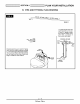
SECTION2 C. TYPICAL SOLDERED PLAN YOUR INSTALLATION COPPER (OR PVC) IN AND OUT PIPES TO SOFTENER DELUXE VALVE MODELS OUT * 1" NPT sweat adaptor OUT IN IN * 1" NPT sweat adaptor c,! .z 1 "NPT J adaptor _, | clip] _t-f _ VALVE INLET la"d aNP_ch included Bypass Valve (included with some models) *NOTE: For plumbing connection, buy 2 sweat adaptors and plumb directly to the inlet-outlet adaptors or bypass valve. Threads on the inlet-outlet adaptors 1" NPT.
SECTION2 PLAN YOUR INSTALLATION D. TYPICAL THREADED IN AND OUT PIPES TO SOFTENER If you are planning a threaded plumbing installation, with a 3-valve bypass, use the drawing in Fig. 4 as a guide. Use union fittings, as needed, to connect the plumbing. DELUXE VALVE MODELS Outside ucets So ft ":!_':_'::" :".... M (Raw W _e ater In) FITTINGS REQUIRED NOT L DENTIFIED Union (2) 90 o Elbow (2/ Pipe (as reg,) IN _ 1" NPT ,o,e _ adaptori_c°,'o_:? _o_V_o_o,_ *NOTE: For 1 in.
li!i ! ::i:i ! ::i:i ! ::iSECTION A. ASSEMBLE S ffi the shut-off valve ffi JJJJJJJJJJJ JJJJJJJJJJ -_"" BYPASS -_ VALVE " Water Meter Pump Electrical Panel dJdJdJdJd MJJJJJJJJJJJJJJJJ MJJJJJJJJJJJJJJJJ Remove 0 If not already done, remove all cardboard or plastic packing pieces from inside the softener. Set the cardboard liner (with parts for installing fastened to it) where you can easily see it, and get to parts as you need them.
[i!i! ::i:i ! ::i:i ! :i SECTION A. ASSEMBLE STEP BY STEP GUIDES TO INSTALL 3 INLET-OUTLET ADAPTORS, OR PLASTIC BYPASS VALVE DELUXE VALVE MODELS INSTALLING BYPASS VALVE, and / or INLET and OUTLET THREADED ADAPTORS Before installing the bypass valve, or threaded adaptor, be sure the turbine and support are firmly in place in the valve outlet port. turbine sensor support port S \ turbine included with softener Valve inlet included with softener INSTALLING black bypass valve or threaded ad
[i!i! ::i:i ! ::i:i ! :i SECTION STEP BY STEP GUIDES TO INSTALL 3 B. INSTALL 3-VALVE BYPASS _ INSTALLING 3 VALVE BYPASS AND IMPORTANT: PIPES When looking at the front of the softener, the inlet is on the right side. If water in your house main water pipe runs from left to right, be sure to use a "cross-over" as shown on page 2-3. (FIG. 9) O Cut the house main water pipe where you will connect the softener. Loosely put together pipe, fittings, and the 3 valves.
li!i ! ::i:i ! ::i:i ! :i SECTION LOCATE Ci I! MOVE STEP BY STEP GUIDES TO INSTALL 3 THE SOFTENER WATER INTO SOFTENER, AND CONNECT PLACE MOVE PIPES SOFTENER INTO PLACE Move the softener into place, onto a level and smooth surface. If needed, put a piece of 3/4" plywood, at least 17" x 20", under the tank. Then put spacers under the plywood to level the softener. Do not put shims or spacers directly under grip under ridge to move so_ener the tank, without the plywood.
[i!i! ::i:i ! ::i:i ! ::i SECTION STEP BY STEP GUIDES TO INSTALL 3 D. CONNECT _1_ CONNECT THE VALVE DRAIN VALVE AND SALT TANK DRAINS HOSE • Keep the hose lower than the drain fitting. (In some homes, to get to a drain you must raise the hose and run it over-head. If you need an overhead drain, do not raise the hose more than 8' above the Take a length of 3 / 8" inside diameter drain tubing and attach one end to the drain fitting (FIG. 12). Use a tube clamp to hold it in place.
[i!i! ::i:i ! ::i:i ! ::i SECTION Ol _ e @ @ e CONNECT BING Take the SALT STEP BY STEP GUIDES TO INSTALL 3 CONNECT TANK VALVE OVERFLOW AND TU- SALT TANK Important: • adaptor and tube clamp (FIG. 12) that are on the small cardboard liner. rubber grommet, tube parts The salt tank overflow is for safety only. If the salt tank should overfill with water, the overflow tubing • Push the grommet into the hole in the salt tank wall so half is inside and half is outside.
li!i ! ::i:i ! ::i:i ! :i SECTION STEP BY STEP GUIDES TO INSTALL 3 E. PRESSURE [] TEST / CHECK HOUSE MAIN WATER SHUTOFF VALVES CAUTION: To avoid water or air pressure damage to softener inner parts, and to flush pipe chips or other residue from the water pipes, be sure to do the following steps exactly as instructed. Look at the picture bypass valve(s). _1_ _Jl in FIG. 15 showing Fully open two cold, the softener.
[i!i! ::i:i ! ::i:i ! ::i SECTION STEP BY STEP GUIDES TO INSTALL 3 F. GROUNDING _ INSTALL GROUNDING THE SOFTENER IN AND / CONNECT WIRE BETWEEN OUT PIPES The house cold water pipe (iron or copper) is often used to ground all electrical outlets in the home. Outlets are grounded to protect you from shock when you touch any electric appliance plugged into the outlet. If you installed the single bypass valve (FIG. 15), the cold water pipe ground is broken.
SECTION3 STEP BY STEP GUIDES TO INSTALL F. GROUNDING _PLUG / CONNECT TO ELECTRICAL IN THE TRANSFORMER Plug the transformer POWER CONNECTING into the electrical TRANSFORMER outlet. Transformer 120V-6OHz Electrical Outlet Power Cable from Face Plat_'13mer INSTALL COVERS Salt Hole After installing your water softener, replace the covers. For the UltraSoft 100, first position the main cover on the softener. Then, set the salt hole cover into the main cover, and lower closed.
INSTALLATION MANUAL MODEL NOS. UItraSoft 425 625.388460 UltraSoft 480 625.388480 UltraSoft 800 625.388800 UItraSoft 880 625.388880 Caution: Read and Follow All Safety Guides Before You Start To Install Your Softener. If you have questions when installing, operating or maintaining your softener, and when setting the timer, call this toll-free number... 1-800-426-9345 www.Ken moreWater.com SAVE THIS MANUAL I PRINTED IN U.S.A.
[ INTRODUCTION This manual gives you the steps needed to install your new Kenmore Water Softener. To better understand how the water softener is installed, and to know what you will need, please read this entire manual before beginning. R O U C I _JNJ_J_J_J_J_ After you have installed the water softener, the included owner's manual tells you how to start, program, operate and maintain it. The owners manual also has the product warranty, and a listing of repair parts available from Sears.
[ii_i_iii_ii_i_iii_ii_i_iii_ii_i_iii_ii_i_iii_ii_i_iii_ii_i_iii_ii_i_ii TABLE OF CONTENTS BEFORE INSTALLING A B A. Safety B. Unpacking C. Water CHECKS & TESTS NO. 1-1 Guides The Water System PAGE 1-2 Softener 1-3 Tests PLAN To Install YOUR INSTALLATION 2-1 O F A. Where The Water Softener B. Tools, Pipe and Fittings, C. Typical Soldered Copper C O D. Typical Threaded In and Out Pipes To Softener- Other Materials (or CPVC) Assemble Inlet-Outlet B. C.
SECTION1 BEFORE INSTALLING A. S C T N SAFETY CHECKS & TESTS GUIDES • Read all steps, guides and rules carefully before installing and using your new water softener. Follow all steps exactly to correctly install. Failure to follow them could cause personal injury or property damage. Reading this book will also help you to get all of the benefits from your water softener. • Your water softener and "clear shown on manual.
SECTION1 BEFORE INSTALLING B. UNPACKING THE WATER CHECKS & TESTS SOFTENER Directions for unpacking the softener are on the top of the shipping carton. This manual, and the owner's manual, were on the small parts cardboard Use care when handling the softener. DO NOT turn upside-down. DO NOT drop, or set on sharp objects that could make a hole in the bottom. The water soft- packing piece. You will need the small parts to install the softener.
I_i_ii_ii .................................... SECTION1 BEFORE INSTALLING C. WATER SYSTEM Has your water supply had a chemical analysis? Please see page A on the inside of the front cover. CHECK YOUR WATER PRESSURE -- For your _ _J _1_ If water pressure during the day is 100 psi or more, pressure during the night may go over 125 psi. Adding a pressure reducing valve may reduce the flow. CHECK _A flow of at least 3 gallons per minute A water is needed.
SECTION2 PLAN YOUR INSTALLATION A. WHERE TO INSTALL THE WATER SOFTENER S Think of the following points as you choose a place to put your softener. (see FIG. 2). Place as close as possible to the pressure tank (well water) or water meter (city water). C T Place water Connect JJJJJJJJJJJ JJJJJJJJJ d_d_d_d_d tub, sump or A grounded, transformer o to the house main softener Be sure wa- (49°C). Hot water will damage inner softener parts.
SECTION2 PLAN YOUR INSTALLATION B. TOOLS, PIPE AND FITTINGS, OTHER MATERIALS NEEDED You must first decide how to run in and out pipes to the softener. Look at your house main water pipe at the point you will connect the softener. Is the pipe soldered copper, glued plastic, or threaded galvanized or brass? What is the pipe size? What kind of pipe and fittings is it easiest for you to work with, and what tools do you have? ALWAYS install a bypass valve or valves.
SECTION2 PLAN YOUR INSTALLATION B. PIPE AND FITTINGS, LEFT PLAN DRAWING YO UR HO USE MAI N WATER R PE * RIGHT * In what direction does the water flow? Be sure to plan IN and OUT piping so water flow is to the softener valve inlet, Plan a crossover if flow is from left to right. CROSS-OVER 120V - 60Hz I1_sII Electrical I1'"U Outlet sift W_aDraw the plans for your In and OUT piping here. Be sure to follow the guides on page 2-2. Include all pipe, fittings and accessories you will use.
SECTION2 C. TYPICAL SOLDERED PLAN YOUR INSTALLATION COPPER (OR PVC) IN AND OUT PIPES TO SOFTENER HIGH PERFORMANCE VALVE MODELS IN AND OUT PLUMBING USING A 3-VALVE BYPASS IN AND OUT PLUMBING USING SEARS BYPASS VALVE (included) s .%"----""----.._ Main_e OPTWAT_R__ " _R .
SECTION2 PLAN YOUR INSTALLATION D. TYPICAL THREADED IN AND OUT PIPES TO SOFTENER HIGH PERFORMANCE VALVE MODELS IN AND OUT PLUMBING USING SEARS BYPASS VALVE (included) outside faucets FITTINGS REQUIRED, NOT IDENTIFIED union (2) pipe (as required) 90 ° elbow (2) __ threaded adaptor ingipeal \ Bypass Valve (included with some models) 2-5 High Performance Valve 4ncO_u_aClh
SECTION3 A. ASSEMBLE S ffi INLET-OUTLET Close the shut-off ADAPTORS, valve Shut off the supply ffi gas or to the water If not already done, JJJJJJJJJJJJ Remove Pump electric Electrical Panel 0 remove 0 the main cov- support are firmly in place. (Fig. 6) BYPASS VALVE: If not already done, put a light coating of silicone grease on the o-ring seals and slide onto the bypass valve. Push the bypass valve into the softener valve as far as it will go.
SECTION3 A. ASSEMBLE STEP BY STEP GUIDES TO INSTALL INLET-OUTLET ADAPTORS, OR PLASTIC BYPASS VALVE INSTALLING BYPASS VALVE, and / or INLET and OUTLET THREADED ADAPTORS Before installing the bypass valve, or copper tube, be sure the turbine and support are firmly in place in the valve outlet port. OUTLET turbine sensor support port r_ \ threaded adaptors (install in softener valve or bypass valve) clip (2) _ INSTALLING black bypass valve or copper tube turbine bypass valve HOLDING CLIPS B
SECTION3 STEP BY STEP GUIDES TO INSTALL B. INSTALL 3-VALVE BYPASS _ INSTALLING 3 VALVE BYPASS AND IMPORTANT: PIPES When looking at the front of the softener, the inlet is on the right side. If water in your house main water pipe runs from left to right, be sure to use a "cross-over" as shown on page 2-3. (FIG. 9) O Cut the house main water pipe where you will connect the softener. Loosely put together pipe, fittings, and the 3 valves. Place valve(s) within easy reach.
SECTION3 STEP BY STEP GUIDES TO INSTALL C. LOCATE WATER SOFTENER, _MOVE THE SOFTENER INTO AND CONNECT PLACE MOVE PIPES SOFTENER INTO PLACE Move the softener into place, onto a level and smooth surface. If needed, put a piece of 3/4" plywood, at least 17" x 20", under the tank. Then put spacers under the plywood to level the softener. Do not put shims or spacers directly under the tank, without the plywood.
SECTION3 STEP BY STE P G UIDES TO INSTALL D. CONNECT _1_ CONNECT THE VALVE DRAIN VALVE AND HOSE Leave an air gap of about 1-1 / 2" between DRAINS • Keep the hose lower than the drain fitting. (In some homes, to get to a drain you must raise the hose and run it over-head. If you need an overhead drain, do not raise the hose more than 8' above the Cut an appropriate length of 3/8" drain tubing (20 ft. roll included) and attach one end to the drain fitting (FIG. 12).
SECTION3 D= _J e @ @ e CONNECT BING Take the SALT STEP BY STE P G UIDES TO INSTALL CONNECT TANK VALVE OVERFLOW AND TU- SALT TANK Important: • adaptor and tube clamp (FIG. 12) that are on the small cardboard liner. rubber grommet, tube parts The salt tank overflow is for safety only. If the salt tank should overfill with water, the overflow tubing • Push the grommet into the hole in the salt tank wall so half is inside and half is outside.
SECTION3 STEP BY STE P G UIDES TO INSTALL E. PRESSURE [] TEST / CHECK HOUSE MAIN WATER SHUTOFF VALVES CAUTION: To avoid water or air pressure damage to softener inner parts, and to flush pipe chips or other residue from the water pipes, be sure to do the following steps exactly as instructed. Look at the picture bypass valve(s). in FIG. 15 showing _1_ Fully open two cold, the softener.
SECTION3 STEP BY STE P G UIDES TO INSTALL F. GROUNDING _ INSTALL GROUNDING THE SOFTENER IN AND / CONNECT WIRE BETWEEN OUT PIPES The house cold water pipe (iron or copper) is often used to ground all electrical outlets in the home. Outlets are grounded to protect you from shock when you touch any electric appliance plugged into the outlet. If you installed the single bypass valve (FIG. 15), the cold water pipe ground is broken.
SECTION3 STEP BY STE P G UIDES TO INSTALL F. GROUNDING _PLUG / CONNECT TO ELECTRICAL IN THE TRANSFORMER Plug the transformer POWER CONNECTING into the electrical TRANSFORMER outlet. Transformer 120V-6OHz Electrical Outlet from Face Plate-_mer INSTALL COVERS After installing your water softener, replace the covers.