A Proposal for New Presentations MULTI PROJECTOR User’s Manual NIPPON AVIONICS CO.,LTD. Head office : 3-20-1 Nishi Shinbashi, Minato-ku, Tokyo Technical Support Information Instrument Service Center, Electronics Equipment Division 2-28-2 Hongo, Seya-ku, Yokohama Zip code : 246-0015 Tel : 81-45-304-8233 To customers : Enter the name and date of the store where you purchased this product. This information will be useful when you ask your dealer for repair.
Thank you for purchasing the MP-15E Multi Projector. Before operating your projector, please read this manual carefully. Specifications Mode Name Type ● Features Ease of operation Easily switch between projecting printed materials to data or video images with a press of a button. • Total cost of ownership With direct access to the OHP, special transparencies are not required saving you time and expense.
Warnings and Safety Precautions ● Warning Symbols To alert the user to important safety precautions, the following symbols are used in this manual and on the product. Make sure you understand what these symbols mean before reading this manual. WARNING : Death or serious injury may result if this warning is ignored. CAUTION NOTE : Injury or damage to the equipment may result if this warning is ignored. : This indicates an item that you should take care of when handling your multi projector.
• Do not look through the lens. • Do not look through the lens into the projector during operation. The powerful rays passing through the lens may damage the eyes. • Do not put the projector in unstable places. • Do not put the projector in unstable places such as on unstable desks or slopes. Doing so may cause the projector to drop or turn over, resulting in injury. • Do not use any voltages other than specified. • Do not use any voltages other than specified. Doing so may cause fire or electric shock.
• • • • • • • • Clean the lens surface with a commercial blower or lens cleaning paper. Wiping with tissue paper or a handkerchief can damage the lens. • To clean the cabinet, operation panel, and glass surface, wipe gently with asoft cloth. For particularly dirty spots, soak the cloth in a neutral detergent mixed in water, wring out well and wipe off the dirt, then use a dry cloth to wipe dry. • Do not wipe the projector with any volatile solvent such as benzine or thinner.
Remedy • The product whose lamp exploded has some small lamp pieces inside. Do not replace the lamp, but return it to the sales office or agent of purchase. Even though the lamp has exploded, never try to replace the lamp by yourself. The lamp pieces may cause injury. • Replacing the lamp • Be sure to turn the lamp off and pull out the power plug when the fan stops, and wait an hour or more before start replacing the lamp.
● Notice This equipment has been tested and found to comply with the limits for a Class A digital device, pursuant to Part 15 of the FCC Rules. These limits are designed to provide reasonable protection against harmful interference when the equipment is operated in a commercial environment. This equipment generates, uses and can radiate radio frequency energy and, if not installed and used in accordance with the instruction manual, may cause harmful interference to radio communications.
Contents Names and Functions of Each Section .............................................9 Projector .................................................................................................................. 9 Input Output Terminals ........................................................................................... 11 Buttons and Indicator Lights - Operation Panel - ................................................... 12 Explanation of Buttons - Adjustment Panel - ...........................
Names and Functions of Each Section Names and Functions of Each Section Projector Document Cover The pickup section for documents and printed matter is located under this cover. See page 29. Adjustment/Operation Panel Buttons for setting adjustment menus and operating the projector are located here. Power ON/STANDBY, input selection, FREEZE, OHP zoom ratio, BRIGHTNESS, and other indicator LEDs are also located here. See pages 12 and 13.
Document Pickup Section Speakers Place documents or printed matter here to project images when OHP is selected. See page 29. Handle Power Input Terminal Plug the power cord into this terminal. See page 18. Air Vent B Air is discharged from the inside to the outside through this vent. Remote Control Sensor I/O Terminal Section Connection terminals for a PC or video deck are located here. See page 11.
Names and Functions of Each Section ■ Input Output Terminals Audio Output Terminal Video Deck Video Input Terminal S-VIDEO TEST PC Audio Input Terminal Video Deck Audio Input Terminal S-VIDEO Video Deck Input Terminal V L VIDEO-IN R OUT IN PC-AUDIO RGB-OUT Test (maintenance) RGB Signal Terminal Output Terminal PC-IN PC Video Input Terminal PC Video Input Terminal Input terminal for the PC analog RGB signals RGB Signal Output Terminal When OHP is selected, OHP images are output.
■ Buttons and Indicator Lights - Operation Panel Power Indicator LED ON/STANDBY LAMP LED LAMP ALARM LED ON/STANDBY Button ALARM VIDEO PC OHP FREEZE Selection Buttons (OHP/PC/Video Source) FREEZE Button BRIGHTNESS BRIGHTNESS Adjustment Button ZOOM ZOOM Adjustment Button ON/STANDBY Button Selection Button (OHP/PC/Video Source) • • • • • ZOOM Adjustment Buttons (enabled only when OHP is selected) BRIGHTNESS Adjustment Buttons • (enabled only when OHP is selected) • FREEZE button • Power Indi
Names and Functions of Each Section ■ Explanation of Buttons - Adjustment Panel - MENU SET MENU Button SET Button ADJUST/VOLUME + / – Button MENU Button • Press this button to display the menu screen, or select menus. • For menu setting details, see page 34 onwards. + / – Button • Press these buttons to select and adjust items selected by the MENU button. • This button can also be used to adjust the volume when the menu screen is not displayed.
Remote Controller Laser Pointer (Beams a laser light when LASER button is pressed.) ON/ STANDBY AUTO SYNC ON/STANDBY button Select button VIDEO AUTO SYNC button Laser Pointer button (The AUTO SYNC button lights in red when the laser is emitting.) Select button (VIDEO) MENU MENU button LASER PC PUSH SET / SET button / / button Select button (OHP) PORTRAIT button (Vertically-oriented display) OHP PORTRAIT FREEZE FREEZE button ZOOM ZOOM button BRIGHT. BRIGHT.
Names and Functions of Each Section ■ Remote Control Operations • Use the remote controller within about 6 meters(6.5 yd) from the remote control sensors (on the front and rear sides) and within 30 degrees to the left and right. This distance may become shorter as the battery wears down. • The remote controller does not work if there are obstacles between the remote controller and the remote sensor on the main unit.
How to Install the Projector ■ Installation sequence Check the installation site and image size. Prepare the screen. Install the input devices. Install the projector. End PC, video deck, etc. See "Projection Distance and Screen Size" on page 17. ■Adjusting the Tilt The position and tilt angle of the projected screen can be adjusted by adjusting the adjustable feet. Press both the left and right tilt adjustment levers to lift the main unit, and release them when the desired height is reached.
How to Install the Projector ■ Projection Distance and Screen Size Use the following diagrams to determine the screen display size and the type of screen required for any given projector location. • The projection distance that provides good focusing is 1.15 m(1.2 yd) to 10 m(11 yd) from the front of the lens. Install the projector within this range. Vertical Dimension Horizontal Dimension Screen Size Screen Size Projection Distance (1.15 m to 10 m/1.
■ Typical Installation ;; ;; ;; ;; ;; ;; 1. Select the installation site Place the projector on an even and stable surface such as a table. ON/STANDBY 2. Connect the power cord (supplied), and press the ( button.) ) button (or ON/ STANDBY ;; ;; ;; ;; ;; ;; 90° 3. Turn the direction of the lens so that it is perpendicular to the screen. Turn the unit to the left or right so that the top and bottom lines of the screen are parallel. ;; ;; ;; ;; ;; ;; Adjustable feet 4.
Connecting to a Personal Computer Connecting to a Personal Computer CAUTION • To protect your projector and external input devices, make sure that all power supplies connected to these devices are turned OFF. • For details of how to use and connect external input devices to be connected to your projector, refer to the user’s manuals accompanying them. • Sometimes images are not displayed properly when displaying on notebook PC LCDs. If this happens, turn the notebook PC display OFF.
About the PC Input and Output Terminals 15-pin mini D-Sub connectors are used for the PC input and output terminals. The following shows the relationship between the pins and the input and output signals. 5 4 10 3 9 2 8 15 14 13 12 1 7 6 11 q RED VIDEO w GREEN VIDEO e BLUE VIDEO r GND t ---- y GND u GND i GND o ---!0 GND !1 !2 !3 !4 !5 GND ---H.SYNC V.SYNC ---- NOTE • This projector uses a 15-pin RGB input and an analog type output terminals.
Connecting to a Personal Computer ■ If images of a personal computer are not projected Check the following if images of a personal computer are not projected, or projected incorrectly. ● If images are not projected If the external output signals from a personal computer are not input to MP-15E, “No PC signal” appears on the MP-15E display. Check the following if “No PC signal” appears. 1 Restart the computer.
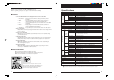
■ Input Signal Compatibility Table (PC video input) The MP-15E supports the signals marked by ● in the following table. Note that on some PC models, flickering and blurring occur in the projected image. If this happens, adjust the screen in the Sync Adjustment menu. Signal Name NTSC RGB PAL/SECAM RGB VGA-GR1 Resolution (Horizontal ✕ Vertical) - Horizontal Frequency Vertical Frequency (kHz) (Hz) 15.7 60 Compatibility ✕ - - 15.6 50 ✕ 640 480 31.5 60 ● VGA-GR2 640 400 31.
Connecting to a Personal Computer ● Basic Connections Rear of MP-15E main unit S-VIDEO TEST V L VIDEO-IN R OUT IN PC-AUDIO RGB-OUT PC-IN Fix the connector cable using the screw-in fasteners. To audio output To speaker terminal on PC input terminals The connector cable model No. differs according to the type of PC.
● Connecting to Apple Macintosh Notebook Excluding Power Book Duo, 100, 140, 145B, 150, 170 Signal cable MPC-VGA (supplied) Display adapter for Power Book To PC-IN terminal Conversion adapter MPA-MAC-P MP-15E NOTE • When connecting the Power Book Duo, the Duo Dock or Mini Dock is required. • The Power Book display adapter is sometimes not supplied with the Power Book. If it is not supplied, buy a separate display adapter from a Macintosh computer store.
Connecting to a Personal Computer ■ Connecting to a Video Deck or Laser Disc Player Images from a video deck or laser disk player can be projected on the large screen. Or Laser Disk Player Video Deck To Video Output Terminal S-VIDEO TEST To Audio Output Terminal V L VIDEO-IN RGB-OUT R OUT IN PC-AUDIO PC-IN Terminal Section on Rear of MP-15E. NOTE • When both VIDEO and S-VIDEO are connected, S-VIDEO is given higher display priority.
Basic Operation ■ Basic operation of PC or video input Preparation : Turn connected devices on. 2,5,6,7 3 4 1 1 Connect the power cord. ON/STANDBY The projector is in the standby mode, and the power indicator LED lights (red). LAMP Press the ON/STANDBY button. The LED lights, and the power indicator LED lights (green). The LAMP LED lights (green). If the LED lights (red) and starts blinking, see page 49. ALARM 2 Main Unit Operation VIDEO PC Select the external input device.
Basic Operation 4 Adjust the focus. Adjust the focus ring on the projection lens until the projected image is sharp. 5 Remote Control Operation Compensate keystone. See “Compensating Keystone” on page 33. KEYSTONE 6 Remote Control Operation Adjust the PC zoom. See “PC Zoom” on page 32. ZOOM 7 Remote Control Operation Adjust the volume.
When You Have Finished Using the Projector 8 9 8 Main Unit Operation ON/STANDBY Turn the lamp off. Press the ON/STANDBY button. (Hold down for at least one second.) “Press ON/STANDBY again to turn off.” is displayed on the projection screen. Remote Control Operation Press the ON/STANDBY button again. The LAMP LED blinks (green), and goes out after about 120 seconds. The power indicator LED lights (red).
Basic Operation ■ Basic Operations in the OHP Mode The functions described here can be operated only when OHP input is selected. 2,3 1 NOTE • The projected image in the OHP display (projection of actual object) may be slightly distorted as a very wideangle lens is used. 1 Place the object you want to project. Open the document cover, and place the document or printed matter you want to project on the document pickup section. Close the document cover.
4 Main Unit Operation BRIGHTNESS Adjust the brightness. Pressing the button on the left darkens the screen, and pressing the button on the right lightens the screen. When the projected image is frozen, brightness cannot be adjusted. Cancel freeze to adjust the brightness. Remote Control Operation BRIGHT. NOTE • When projecting dark documents or printed matter, adjust to lighten the screen, and when projecting bright documents or printed matter, adjust to darken the screen. 5 Freeze the screen.
Basic Operation Document Orientation and Pickup Size Place the document or printed matter face down at the orientation shown in the figure below. CBA cba 288 mm/11.3 in (pickup size) 288 mm/11.3 in (pickup size) 210 mm/8.3 in (paper size) Parts protruding outside the pickup area are not projected on the screen. To project these parts, move the paper. 216 mm/8.5 in (pickup size) A4 vertical orientation 297 mm/11.6 in (paper size) 297 mm/11.6 in (paper size) A4 horizontal orientation 210 mm/8.
■ PC Zoom The functions described here can be operated only when PC input is selected. The zoom function can be operated on the remote controller. 1 Main Unit Operation VIDEO PC Select the input. Select PC (personal computer) as the video source to be displayed. The PC input image is displayed. * You can select the input on either the main unit or the remote controller. OHP Remote Control Operation PC VIDEO OHP 2 Remote Control Operation ZOOM Select the zoom ratio.
Basic Operation ■ Compensating Keystone When keystone compensation is performed, the resolution at the top (or bottom) of the screen is reduced, making small characters harder to read. To prevent this, place the projector on as level a table as possible, and set “Keystone” in the “Setting” menu to “0”. (For details of how to set this, see “Performing Various Adjustments” on page 34.
■ Performing Various Adjustments Menu Structure You can perform various adjustments and make various settings by operating the buttons with the menu screen displayed on the projection screen. To display the main menu screen, connect the PC or video deck, and press the button (or MENU button) with the PC or video deck turned on. Move to the required menu from the main menu screen. The figure below shows how to move between the main menu and menu screens.
Basic Operation Description of Menu Items The following describes each of the menu screens, and the items and functions that can be set in these menu screens. For details of how to set these menu items, see “Basic Operation” on page 38.
◆ Setting Setting Input signal 1024 X 768 Keystone Menu Item 48.2KHz Setting Item Description 60Hz -100 ~ +100 Compensates the keystone of the image. ON/OFF Sets the auto power off function Auto power off ON/OFF. When auto power off is set to ON, the projector automatically enters the standby mode if no signals are input for a fixed period of time (about 15 minutes). ON/OFF Sets whether or not to display the Startup screen logo while the lamp is lit.
Basic Operation ◆ Volume (only when PC input and video deck input is selected) Volume Menu Item Volume Setting Item Description – Adjusts the volume. Quit ◆ Language Selection Language selection Menu Item English Language selection Setting Item English Japanese Description Sets the language of the menu display.
■ Basic Operation The following describes basic operations in the following menus: “Image Adjustment”, “Sync Adjustment”, “Setting”, “Lamp Setting”, “Volume”, “Language Selection”, “Video Adjustment”, “Projection Mode”, and “Video Select” with the exception of “Memory”, which is described on page 42. Main Unit Operation 1 1,2 MENU Press the button (or the MENU button). The main menu is displayed.
Basic Operation 3 SET Press the button (or the button). The menu screen for the item you want to set is displayed. To return to the initial settings when you bought the projector, select “Standard” and press the button (or button) in the “Image adjustment”, “Sync adjustment”, “Setting” or “Video adjustment” menus.
Main Unit Operation 4-2 Press the / buttons (or to select “ON” or “OFF”. buttons) Setting 4-1 Input signal 1024 X 768 Keystone MENU SET 48.2KHz 0 Auto power off O N / OFF Start up screen O N / OFF Quit Standard ADJUST/VOLUME 60Hz When adjusting in single point units Menu items that require adjustment in single point units are “Contrast”, “Red”, “Blue”, “Clock”, “Phase”, “Horizontal”, “Vertical”, “Keystone”, “Tint”, “Color”, “Sharpness”, and “Volume”.
Basic Operation 4-2 Main Unit Operation Press the / buttons (or to adjust the setting. buttons) Sync adjustment 4-1, 5 5 MENU SET Clock 0 Phase 0 Horizontal 9 15 Vertical Standard ADJUST/VOLUME Quit Others Other menu items include “Language selection”, “Projection mode” and “Video select”. For details of menu items, see page 35. 4-2 Remote Control Operation 4-1 MENU Press the button (or buttons) to select the item you want to set, and press the button (or button).
■ About the Memory Menu If you have made adjustments to the size of an image, noise or flicker, or the horizontal and vertical positions when you have selected PC input, the details of these settings can be saved to memory. You can also call up details of setups that you have saved. When you first buy your projector, nothing is set to these memory items. ● How to Save 1 Adjust the image display in the Sync Adjustment menu (page 35). 2 Select "Memory" in the main menu.
Basic Operation ● How to Load Saved Settings 1 Select “Memory” in the main menu. Memor y Save Load Quit 2 Select "Load". MENU Load 0x0 0 Hz 1280 x 720 60 Hz 1024 x 768 60 Hz 0x0 0 Hz 0x0 0 Hz Press the button (or buttons) to select the data to be loaded. Select an item to which saved data is registered. The message “Load?” is displayed as shown below. If you select “YES”, the item is loaded and the menu automatically disappears.
Maintenance ■ Protection Against Overheating Your projector is provided with internal protection circuits for preventing fire and damage to internal components due to abnormal temperature. When the power indicator LED is blinking: ● Action 1. Unplug the power plug from the power outlet. 2. Check the air filter for dirt. * If the LAMP LED also is blinking at the same time, replace the lamp. For details of how to replace the lamp, see page 46. When the ALARM LED is lit: ● Action 1.
Maintenance ● When the power fails (all LEDs are off with the power ON) ❍ Action 1. Unplug the power plug from the power outlet. 2. Check the following and take corrective actions. Is the ambient temperature more than 35°C (95°F)? Are any vent holes blocked? Is the lamp unit cover securely in place? A probable cause is an internal circuit problem. Use your projector within an ambient temperature of 0°C to 35°C (32°F to 95°F). Place your projector away from walls and other objects.
■Lamp Unit Replacement The target replacement time of the lamp used on this projector is 950 hours. (This may be shortened depending on the conditions of use.) Since there is a high possibility of lamp explosion if the cumulative usage time exceeds more than 1000 hours, the power to the lamp is cut off at 1000 hours. In the following instances where the cumulative usage time of the lamp is more than 950 hours, replace the lamp unit (sold separately).
Maintenance 2 Loosen the lamp unit retaining screw. Loosen the lamp unit screw. (1 piece) 3 Draw out the lamp unit. Hold the handle and lift the lamp unit upward. 4 Install a new lamp unit. q Hold the lamp unit and push it in. w Tighten the lamp unit retaining screw. e Turn down the handle of the lamp unit. r Install the lamp unit cover, and tighten the two retaining screws. 5 MENU Reset the lamp usage time. Perform the following in the standby state.
■ Cleaning the Air Filter The air filter is an important part as it keeps the optical components inside your projector free from dirt and dust. A clogged air filter can cause the temperature to rise inside your projector and the fan speed to increase. This, in turn, may reduce lamp life or cause the projector to malfunction. The air filter should be cleaned regularly (about once a month if the projector is used four hours a day).
Troubleshooting Troubleshooting If you think a problem has occurred, check the following items before asking for a repair. Symptom Power is not on. To be Checked Page(s) • Verify that the power cord is plugged in. 18 • Verify that the lamp unit cover is installed. 46 The projection lamp does not light. • Verify that the lamp has not blown. 46 • Verify that the air filter is installed. 48 • Verify the internal temperature.
Limited Warranty & Warranty Service LIMITED WARRANTY PERIOD • The Limited Warranty is valid for one year from the date of purchase. This Limited Warranty does not cover consumable parts such as lamp and air filter. • Some repairs are chargeable to the user even within the effective Limited Warranty period. • For details of repairs after the Limited Warranty period has elapsed, consult your dealer. Repairs can be performed at cost to the user if the functions of the product can be maintained.
Thank you for purchasing the MP-15E Multi Projector. Before operating your projector, please read this manual carefully. Specifications Mode Name Type ● Features Ease of operation Easily switch between projecting printed materials to data or video images with a press of a button. • Total cost of ownership With direct access to the OHP, special transparencies are not required saving you time and expense.
A Proposal for New Presentations MULTI PROJECTOR User’s Manual NIPPON AVIONICS CO.,LTD. Head office : 3-20-1 Nishi Shinbashi, Minato-ku, Tokyo Technical Support Information Instrument Service Center, Electronics Equipment Division 2-28-2 Hongo, Seya-ku, Yokohama Zip code : 246-0015 Tel : 81-45-304-8233 To customers : Enter the name and date of the store where you purchased this product. This information will be useful when you ask your dealer for repair.