User-Manual • AlarmManager-BASIC/PRO • MultiSensors and KeyPad • Accessories kentix.
Content 1. Introduction and summary! 4 1.1. Features! 4 1.2. Applications! 4 1.3. Safety note! 4 2. Connection examples and installation notes! 5 2.1. CompleteSet 1! 5 2.2. CompleteSet 2! 5 2.3. CompleteSet with optional equipment ! 6 2.4. Alarm-inputs! 7 2.5. Relay contacts ! 7 2.6. Power supply ! 7 3. Overview KENTIX System Topology! 4. AlarmManager-BASIC/PRO! 8 9 4.1. Login to the AlarmManager! 9 4.2. Changing IP-Settings ! 9 4.3.
5.7.3. Opening of the casing / replacement of battery! 34 5.7.4. Adding a MultiSensor-Door / -RACK-MINI! 34 5.7.5. Identifying a MultiSensor-Door / -RACK-MINI! 34 5.7.6. Profile description! 35 5.7.7. Testing the settings ! 5.8. 35 MultiSensor-Rack! 36 5.8.1. Safety note and installation! 36 5.8.2. Default settings ! 36 5.8.3. Overview connections ! 37 5.8.4. Recommended installation! 37 5.8.5. ConfigurationConfiguration! 38 5.8.6. EnergySensor - Energy! 39 5.8.7. Control! 42 5.8.
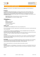
Introduction and summary Thank you for your decision to buy a KENTIX monitoring solution based on the KENTIX MultiSensor technology. Features The KENTIX AlarmManager-BASIC/PRO is the central system unit, where all the information of the MultiSensors are collected. The AlarmManager is installed in the server room or rack. It controls and forwards all alarm and fault messages to the responsible persons. The configuration is done with a comfortable PC client - the Kentix ControlCenter.
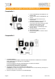
Connection examples and installation notes CompleteSet 1 1. Connect AlarmManager and MultiSensor via Modular cable. 2. Connect power supply to AlarmManager and current. 3. Download, install and execute Kentix ControlCenter. (Software-Download on www.kentix.de) 4. Enter Kentix-Default-IP-Address (192.168.100.222) and the default user data (admin/password) and press „Login“. (check your own network-settings). 5. Setup IP-Address of AlarmManager in the Network settings. 6. Add Radio Sensor in „Sensor-Devices“.
CompleteSet with optional equipment KMS-Door 1. MultiSensor-LAN: Establish network connection and external power supply, if needed. Connect to the sensor via browser by entering the Default-IP (192.168.100.223). Press „Login“ to reach configurations menu (Username: „admin“, Password: „password“). Activate AlarmManager communication in the network-section. After saving the settings and a restart, the sensor can be configured with the Kentix ControlCenter. 2.
Alarm-inputs When installing the device follow the instructions in this manual. Please note polarity and technical data of the inputs. Relay contacts When installing the device follow the instructions listed in this manual. Connected devices must installed properly following the specifications in this manual. Pay particular attention to the allowed supply voltages and services for the various consumers in the technical data-sheet. Power supply The devices are supplied with a DC voltage between 10-32VDC.
Overview KENTIX System Topology ✓ The AlarmManager is the central unit. With the BASIC-Version up to 10 MultiSensors and 3 KeyPad wall-mount keyboards can be connected. The PRO-Version supports up to 100 devices (MultiSensors-RF/-LAN/-RACK/LAN-RF/-Door and KeyPads). ✓ The KENTIX components are communicating via radio (ZigBee ®) in the 2.4GHz ISM band. The MultiSensors and KeyPads are working in a mesh network and communicate with each other. ✓ Start each new project always with a CompleteSet.
AlarmManager-BASIC/PRO Login to the AlarmManager The PC-Client Kentix ControlCenter displays a Login-screen after starting the Application. To log in, enter IP-Address and user data for your AlarmManager. With the first commissioning, use the default IP-Address 192.168.100.222 and the user data admin/password to log in. NOTE Only users with the permission „Administrator“ are allowed to make changes to the AlarmManager.
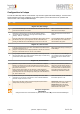
Configuration in 8 steps To make an initial setup with the ControlCenter only the three register-tabs "Base-Settings - User Accounts Sensor-Devices“ have to be configured. On the other registers you find the functions for operation and remote control of the configured AlarmManager. No Step Comment Register tab „Base settings“ 1 Connect the AlarmManager via LAN cable to the PC. The yellow LED on the LAN connector indicates a connection.
Visual and acoustic signaling AlarmManager ! ! LED-POWER: ! LED-GSM:! ! ! LED-ARMED:! LED-ALARM: ! ! ! ! ! ! ! Lights after connection to the power supply Flashes: Booked into GSM network, ready for communication.
Alarm zones MultiSensors connected to the AlarmManager and also the inputs of Kentix IO-modules can be assigned to different alarm zones. With this option a separation into different areas can be realized. Every zone can be switched to armed or disarmed state and send alarms independent from the other alarm zones. For the configuration, add the desired number of zones in the alarm zones section of the base settings and enter a name for every zone. After this assign the sensors to the desired zone.
User accounts In the user accounts the setup of the permissions and the alarming is done. Only if the required user data is entered, a user can control the AlarmManager or request information.
SMS commands for remote control of AlarmManager The AlarmManager reports not only all the alarms via SMS, it can be also remotely controlled via simple SMS commands from a mobile phone. This brings the big advantage of having the central alarm system in your pocket and remotely setting the system to the desired states. The AlarmManager can be armed or disarmed and alarms can be acknowledged remotely.
Advanced settings - AlarmManager-BASIC and -PRO In the advanced settings, additional functions of the AlarmManager can be activated. General Settings Backup folder The path to the backup of the AlarmManager configurations-file is set here. Alarm functions Setup the behavior of the AlarmManager for existing alarms here. The acoustic feedback (buzzers of AlarmManager and MultiSensors) can be activated or deactivated as needed, except the CO-alarming.
Advanced settings - AlarmManager-PRO only Network Cameras The AlarmManager-PRO can control cameras in its network to start the recording of a video or picture (depends on the camera features). Enter the IP-address and the port of the camera here. Take the command to start a recording out of the cameras documentation. Enter the command as an URL without entering the IP-address in the command-field (e.g. „/command=...“). For Mobotix and AXIS cameras predefined commands can be chosen via the pulldown menu.
MIB for SNMP-Systems For the AlarmManager-PRO a MIB (Management Information Base) is available, which describes the information that can be requested or modified by a SNMP-System (z.B. PRTG, OpManager or WhatsUp Gold). The single values in it are identified and requested via the OID (Object Identifier). Every value has his own specific OID. The following list shows the structure of the AlarmManager-MIB and gives an overview of the values that can be requested: ๏ state - alarm1 - alarm2 - ...
Execution of Firmware Updates We are always looking to include innovations of development in our products and to ensure their faultless operation. Therefor we release updates in regular intervals. To execute an update pay attention to the following steps. No Step Comment 1 Download the actual version of the Kentix ControlCenter from the Kentix Website and install it. Find the software in the „Info & Support“ section under „Software & Manuals“.
Connections - AlarmManager-BASIC/PRO GSM ZigBee® According to the two types of installation "Plug‘n Play" or "wired connection" you will find all connections of the AlarmManager in the following overview. With the "Plug'n Play" installation you only need to open the case to insert the SIM card. Pull the sides of the case a bit apart. The cover slips right out of the groove and can easily be lifted off. You can insert the fixed connection cable from the rear of the chassis.
External I/Os AlarmManager-BASIC/PRO Examples of the external circuit of the AlarmManager. Shows the internal 12-pin terminal of the AlarmManager. The internal circuit of inputs and outputs is shown schematically for better understanding. The logic of the alarm inputs can be rotated in the ControlCenter. Example 1: Wired with power supply via the internal 12-pin terminal. Example 2: Power supply via the external plug supply, just the alarm-inputs are connected.
License Management In contrast to the AlarmManager-BASIC, the PRO-version contains additional useful features like e.g. connecting network-enabled MultiSensors or adding IO-modules. Having the same technical design, there is the possibility to upgrade an AlarmManager-BASIC via a license key to the PRO-Version with the Kentix ControlCenter, if required. A valid license key can be purchased via our sales department (s.a. www.kentix.de). Page 21 ! ! ! ! (08-2014, subject to change) kentix.
MultiSensors According to the two types of installation "Plug‘n Play" or "wired connection" you can find all connections of the MultiSensor in the following overview. To remove the cover pull the sides of the case a bit apart. The cover slips right out of the groove and can easily be lifted off (see section 5.6 - „How to open the MultiSensor“). You can push the RF „learn button“ or insert the fixed connection cable from the rear of the chassis.
External I/Os of MultiSensors Examples of external circuits of the MultiSensors. This shows the internal 8-pin terminal of the MultiSensor. The internal circuit of inputs and outputs is shown schematically for better understanding. The logic of the alarm inputs can be rotated in the ControlCenter. Running in standalone mode, this is also possible via the MultiSensor-LANs web interface. Example: Wired connection with power supply via internal terminal.
MultiSensor-RF It is not necessary to configure the MultiSensor-RF. Updating it is also not necessary/possible. For the setup of a MultiSensor-RF follow the steps in the configuration on page 9. Learn Button between PCB and chassis. IMPORTANT! Operating the learn-button just with an non conducting, flat object. Otherwise it may short circuits.
MultiSensor-LAN In contrast to the MultiSensor-RF with radio interface the MultiSensor-LAN can also be used stand-alone without an AlarmManager. For configuration in stand-alone operation a web server is integrated, which allows you to configure the device via LAN and a web browser. With the SNMP interface, an integration in network management systems is possible. Connection via PC:! ! ! ! ! ! ! Connect the LAN jack of the MultiSensor-LAN with your network and your PC using a LAN cable.
Software function MultiSensor-LAN In the following, the stand-alone functionality of the integrated web server is described. For the described functionality no AlarmManager is required. When operating the MultiSensor-LAN with the AlarmManagerPRO, the AlarmManager controls the configuration and monitoring functions. Dashboard MultiSensor values and status: Display of the sensor measurements and alarm conditions. This display will be actualized all 5 seconds.
Navigation Dashboard! Login! ! Configuration! System!! ! ! ! ! Help ! ! Logout! ! ! ! ! ! ! ! ! ! - Starting page with measurement table, control of the 2nd digital output, logbook - User login - Basic configuration, MultiSensor (Sensor- and alarm settings), Users (Login,E-Mail) - System information (software version), test functions, configuration management, firmware update, device reset - logbook - Help and support information - User logout Configuration - Basic configuration Device name Configuration
E-Mail If the MultiSensor should be able to send e-mails in the case of alarm to a configured user, it is necessary to set an e-mail server (SMTP or ESMTP). When you have set a DNS server, which is configured in the DNS settings, you can use the DNS name of the e-mail server here. With using ESMTP you can here enter the email access data, which you can obtain from your e-mail provider. Depending on the E-mail server, a encryption method might be necessary.
Sensor-Vibration Alarm settings for the sensitivity of the internal vibration sensor. The sensitivity can be adjusted in 3 levels. If necessary the vibration sensor can also be completely turned of. NOTE! The vibration sensor in the MultiSensor is first available in devices delivered in 01/2014 or later. Arm-Disarm time Switching time for the time-controlled arming and disarming from the integrated motion detection. To use it, a time server (NTP) must be set in the network settings. Ext.
System System information Shows the Firmware version number of the MultiSensor-LAN. The actual firmware can be found on the Kentix Website in the section „Software & manuals“. Test features Test your E-Mail and SNMP settings via the two Buttons. The sending of E-Mails or traps is recorded in the logbook. Backup configuration For backup-purposes the actual configuration of the MultiSensor can be downloaded here. Restore configuration Loads a previously created backup into the device and restarts it.
MultiSensor-Door / MultiSensor-RACK-MINI The MultiSensor-Door / -RACK-MINI is designed for an efficient intrusion detection on doors or windows or for a specific environmental monitoring in a server rack. Depending on its purpose there are two different models: 1. The battery-powered MultiSensor-Door for a flexible application on doors, windows or other moveable objects. 2. The USB-powered MultiSensor-RACK-Mini for a cabled maintenance-free application (no battery changes required) e.g. on server-racks.
Mounting instructions The MultiSensor-Door / -RACK-MINI is equipped with several different sensors.
Usage of the reed contact The reed contact extends the MultiSensor-Door / -RACK-MINI by an additional alarm contact for the definite open/closed detection of a door or window. The contact reacts to magnetic fields (magnet contained in package). For the installation a wiring is not necessary. To ensure the functionality of the contact, take care to not exceed the maximum distance of one centimeter between magnet and casing and orientated to one side of the casing of the MultiSensor.
Opening of the casing / replacement of battery The board of the MultiSensor-Door / -RACK-MINI is fixed in the lid of the casing which is connected to the bottom part with two screws. To open the casing remove the two screws on the top and bottom side and pull the lid away from the bottom part. Take the battery out of the mounting and replace it with an equivalent type (see data sheet). NOTE! The battery level of the MultiSensor-Door can be read out with the ControlCenter.
Profile description The MultiSensor-Door / -RACK-MINI is configured for its intended use with the help of so called door-profiles and an associated sensitivity. With these two options the threshold values of the sensor are defined. Choose the door-profile, which most likely corresponds to the intended use. Find an overview of the sensitivity levels in the table below: Sensitivity level Alarm triggering Low The threshold values of the sensor are high.
MultiSensor-Rack The MultiSensor-RACK can be operated as stand alone device, but also in combination with an AlarmManager-PRO. The AlarmManager then controls the environmental sensors. For configuration in stand alone operation a web server is integrated, which allows you to control and setup the device via LAN and a web browser. Over the SNMP interface, an integration in network management systems is possible. Safety note and installation In case of a power failure, the settings are not lost.
sc ro l cro l ba ck ll f o r Sy wa ste rd m sta te Di sp la Di sp lay D OL E nti xS Ke ys Di sp lay r ys k-Po tem rt xS ys -jack tem 1 -j a ck 2 tw o Ke nti Ne Re se t-B utt on Overview connections PDU-1 (Main PDU) • Independent of PDU-2 • Max. power consumption 3.600VA • Internal protection 2x10A, time lag fuse • Total load over all 4 outputs max. 16A • Power Strip switchable • Energy measurement outlet 1-4 • Main equipment supply - Electronics PDU-2 • Independent of PDU-1 • Max.
1. If possible, install the MultiSensor-RACK at the top position in the rack and leave 1 height unit free below the device. This ensures that the environment sensors can detect the actual state in the rack. 2. For the installation of the mounting brackets only use the included screws. The mounting brackets can be attached to two different positions for installation either to the front or to the back support rail. 3.
EnergySensor - Energy Shows all actual energy measurement values for PDU 1+2 (PDU=Power Distribution Unit), the energy consumption with costs and the alarm state in one table. Voltage Display of the actual mains voltage in volt (V). Flicker Display of voltage drops of the supply voltage over a configured period of time (number of half-waves, minimum 1 half-wave) for each PDU as time value / time. Always the last appearance of a voltage drop will be displayed.
Active power The active power (P) shows the actual power of the PDU. Its calculated by multiplying voltage, current and the power factor. Apparent power Total power of the PDU in volt ampere (VA). It results from the idle power and the active power. Power factor The power factor is the ratio between active power and apparent power. It indicates which part of the apparent power is converted to the desired active power.
EnergySensor - Monitoring Graphical display of the recorded active power and energy consumption and costs. The recording is stored for up to 1 year. If the memory of the recording is full, the oldest values will be deleted automatically. The real time graph shows the actual voltage profile, current and peak voltage for the last minute. Peak alarms will also be displayed. An occurring peak alarm will also be stored for later viewing. Page 41 ! ! ! ! (08-2014, subject to change) kentix.
Control Switch alarm output 2 Changes the state of the 2nd alarm output (output 1 is controlled by the alarming) for the entered switching time. If „0“ is entered for the time, the output stays permanently switched on. For switching, the user password has to be entered. Default state of the output is 0. PDU 1/2 - Switch outputs Switches output 1/2 of the PDU on or off. If the value for the switching time is „0“ or empty, the PDU is switched permanently. For switching, the user password has to be entered.
Configuration - EnergySensor With the following settings set the limits for the alarm triggering of the energy sensors. If an alarm is triggered, e-mails will be sent to the configured users and the buzzer is activated. The configuration has to be made for each PDU. Name Assign the displayed name for each PDU. On an alarm the name will also be shown in the notification (e-mail / SMS). Line voltage / frequency Sets the regional dependent default values for the external power supplement.
Alarm handling The Retrigger time defines, after which time the alarms Flicker, Swell or Peak are reset for the next triggering. This setting avoids that an event which persists for a longer period will lead to a repeated alarming in short distances of time. Costs Value for the costs per kilowatt hour and the monetary unit. Reset energy consumption Sets the internal consumption counter of the MultiSensor-RACK back to 0 and deletes all recorded data.
Configuration of the vibration sensor Define the triggering threshold for the integrated vibration sensor. The alarm is triggered, when the threshold is exceeded. The trigger sensitivity can be adjusted to detect slight vibrations (e.g. moving of the rack) as well as heavy vibrations (bumps or movement of the MultiSensor-RACK) can be detected. Kentix-System-jacks at the MultiSensor-RACK With the two Kentix-System-jacks on the front of the MultiSensor-RACK external components like e.g.
Control a network camera with MultiSensor-LAN/RACK The MultiSensor-RACK offers the possibility to send a control sequence as a HTTP request to any IP ready network camera in case of an alarm. So in addition to the e-mail alerting also a video picture or a video sequence can be sent. The transmission from the video picture is done by the camera. The information to control the camera has to be inserted into the „cam.ini“ file.
Perform software updates on MultiSensor-LAN/RACK The MultiSensor-LAN/RACK offers the possibility to actualize its software via the integrated FTP-server. Actual software updates are available in the software section on www.kentix.de. To check the actual installed software version, open the sensor‘s web server and open the system information in the „System“ section. To perform an update follow these steps: Nr Step 1 Ensure that the internal FTP-Server of the MultiSensor is activated.
How to open the case of MultiSensor and AlarmManager The device lids of the MultiSensor-RF/LAN or AlarmManager are jammed in one surrounding groove on the device bottom part with the electronics. The lid can be lifted without tools by slightly pulling it apart on its sides. Proceed as follow: Open the device lid: 1. Lay down the device with the port side forward. 2. Pull the lid at the sides apart sightly (see picture). 3. The lid will snap out from the surrounding groove with a clicking noise. 4.
KeyPad The KeyPad is used for arm-disarm switching of the AlarmManager on the ground. The KeyPad is just like the MultiSensors integrated into the ZigBee© wireless network of the AlarmManager. However, note that the KeyPad does not work as a router and can not extend the network range. Note that the KeyPad turns on only after pressing one of the three function keys. The duty cycle is then about 10 seconds. During this time you can select appropriate functions or communicate with the ControlCenter.
Operation KeyPad First press the desired function key (arm, disarm, zone) and then enter your personal 4-digit code. The function is triggered immediately after entering the fourth and last code digit. Each key-press is acknowledged with an acoustic "beep". The selected function is indicated by an LED in the button. By pressing one of the keys "arming" or "disarming" followed by entering your personal code the zone assigned to the KeyPad is switched.
Enhancements With the Alarm inputs at the terminal blocks or the system jacks of AlarmManager and MultiSensor it is possible to connect external components like door-contacts or leakage-sensors. In the following you see connection examples for the leakage-sensor available at Kentix. Leakage-sensor The leakage-sensor is already prepared with a RJ45-connector for Kentix devices. Powering is also realized via this connector.
Connection example 2: Leakage-sensor connected to MultiSensor MultiSensor-RF/LAN KENTIX Power-Adapter Leakage-Sensor KENTIX System-jack Plug the connection cable of the leakage-sensor into one of the jacks of the Kentix Power-Adapter (KIO1). Connect the MultiSensor to the Power-Adapter with the modular cable (sent with the Power-Adapter). Connect the delivered power supply to the Power-Adapter for currency.
Kentix Power-Adapter (KIO1) The Kentix I/O Power-Adapter is used to expand your Kentix-solution to include additional components. With the Adapter it‘s possible to supply power to 2 additional devices. Depending on your requirements the alarm via the external inputs can be activated or deactivated. Figure 1 shows the back of a Power-Adapter with the jumpers set (extraditable state) e.g. to use it with a leakage-sensor.
Kentix IO-Modules The AlarmManager-PRO can be extended by additional digital Inputs and Outputs via special Expansion modules. For this 2 external modules (KIO7052 with 8 digital Inputs / Outputs and KIO7053 with 16 digital Inputs) are available. Both modules are configured via a Web browser and are queried by the AlarmManager over the network. Commissioning and Configuration Depending on the module type it can be powered via PoE or with an external power supply.
MultiSensor-LAN-RF (LAN-ZigBee Repeater) The MultiSensor-LAN-RF offers the same functionality as the MultiSensor-LAN. Moreover it allows the creation of a dedicated radio network. With this option it is possible to realize a connection to distant RF-Components (MultiSensor-RF / -Door / KeyPads) via LAN/WAN. The configuration of the repeater and the connected components is done via the Kentix ControlCenter.
Kentix AlarmManager Smartphone-App With the Kentix-App a monitoring and control of a Kentix System via iPhone / iPad or Android devices is possible. In the following, functions and control of the app are described. The Profile menu When starting the app the profile selection menu is displayed. With the „+“ Button in the upper right edge a new profile is created. To differentiate between multiple devices, enter a unique name and choose the device type. Enter IP-address, username and password of the device.
SMS Control When the AlarmManager cannot be accessed via the local network, it can be switched via SMS commands. Trying to access without network connection, the app automatically starts into the corresponding menu, when a telephone number for the AlarmManager is entered in the profile. Before sending the SMS-text the message has to be confirmed.
Data sheets Data sheet AlarmManager-BASIC/PRO (KAM-BASIC/PRO) Number of MultiSensor (KAM-BASIC) Number of MultiSensor (KAM-PRO) Max 10 pc MultiSensor-RF Max 100 pc MultiSensor-RF / -LAN / -RACK / -DOOR / -RACK-MINI Number of KeyPad (KAM-BASIC) Number of KeyPad (KAM-PRO) Max 3 pc KeyPad connectable Max 100 pc KeyPad connectable Internal Buzzer 85dB, 2.3kHz Ext. alarm inputs 1 x alarm input (Armed-Active, Always-Active) 1 x external arm/disarm Both for external potential-free contacts Ext.
Data sheet MultiSensor-RF (KMS-RF) Connectable devices AlarmManager-BASIC (KAM-BASIC) AlarmManager-PRO (KAM-PRO) Sensor - temperature range -20 to 99°C / -3 to 210°F (exactness ± 0,5°) Sensor - relative humidity range 0 to 100% (exactness ± 3%) Dew point calculated in °C/°F Sensor - motion PIR sensor, adjustable responsivity detection cone: 100° range: approx. 8m Sensor - vibration 3 axes vibration sensor (adjustable) Sensor - carbon monoxide (CO) 0-10.
Data sheet MultiSensor-LAN (KMS-LAN) Connectable devices Stand-Alone operation (integrated web server) AlarmManager-PRO Sensor - temperature range -20 to 99°C / -3 to 210°F (exactness ± 0,5°) Sensor - Relative humidity range 0 to 100% (exactness ± 3%) Dew point calculated in °C/°F Sensor - motion PIR sensor, trigger sensitivity configurable detection cone: approx. 100° range: approx. 8m Sensor - vibration 3 axes vibration sensor (adjustable) Sensor - carbon monoxide (CO) 0-10.
Data sheet MultiSensor-LAN-RF (KMS-LAN-RF) Connectable devices Stand-Alone operation (integrated web server) AlarmManager-PRO Sensor - temperature range -20 to 99°C / -3 to 210°F (exactness ± 0,5°) Sensor - Relative humidity range 0 to 100% (exactness ± 3%) Dew point calculated in °C/°F Sensor - motion PIR sensor, trigger sensitivity configurable detection cone: approx. 100° range: approx. 8m Sensor - vibration 3 axes vibration sensor (adjustable) Sensor - carbon monoxide (CO) 0-10.
Data sheet MultiSensor-RACK (KMS-RACK) Connectable devices Stand-Alone operation (Integrated Web-Server) AlarmManager-PRO Sensor - temperature range -20 to 99°C / -3 to 210°F (exactness ± 0,5°) Sensor - Relative humidity range 0 to 100% (exactness ± 3%) Dew point calculated in °C/°F Sensor - motion 3 axes vibration sensor (adjustable) Sensor - carbon monoxide (CO) Fire detection via CO-Sensor Internal resolution: 20-200ppm (0-100%) adjustable Sensor-lifetime: 5 years (replaceable) Buzzer 85dB,
Data sheet MultiSensor-Door (KMS-Door) Connectable devices AlarmManager-BASIC (KAM-BASIC) AlarmManager-PRO (KAM-PRO) Sensor - temperature range -20 to 99°C / -3 to 210°F (exactness ± 0,5°) Sensor - Relative humidity range 0 to 100% (exactness ± 3%) Dew point calculated in °C/°F Sensor - Acceleration sensor 0-3G, 3 axes, adjustable sensitivity Sensor - Gyrometre angular sensitivity adjustable (5-360°, 3 axes) Buzzer 65dB, 2.
Data sheet MultiSensor-RACK-MINI (KMS-RACK-MINI) Connectable devices AlarmManager-BASIC (KAM-BASIC) AlarmManager-PRO (KAM-PRO) Sensor - temperature range -20 to 99°C / -3 to 210°F (exactness ± 0,5°) Sensor - Relative humidity range 0 to 100% (exactness ± 3%) Dew point calculated in °C/°F Sensor - Acceleration sensor 0-3G, 3 axes, adjustable sensitivity Sensor - Gyrometre angular sensitivity adjustable (5-360°, 3 axes) Buzzer 65dB, 2.
Data sheet KeyPad (KKP) Connectable devices AlarmManager-BASIC/PRO MultiSensor-LAN-RF Buzzer 70dB, 2.3kHz LED Zone (RED/GREEN) Arm (RED/GREEN) Disarm (RED/GREEN) Radio ZigBee® 2,4GHz ISM band +3dBm output power, IEEE802.15.4, encryption AES 128 Bit Power supply (battery) Battery 2 pc. 1.5V/AAA Battery life approx. 3 years (without RFID) Battery life approx. 2 years (with RFID) depending on the number of switching cycles Chassis Material: PS 135 x 90 x 19 mm Weight ca.
Data sheet digital I/O expansion-module (KIO7052) Front Back Pin assignment KIO7052 Description Expansion module for connection to the AlarmManager-PRO. This module extends the external inputs and outputs of AlarmManager on additional 8 digital inputs and 8 digital outputs. Communication is via Ethernet, so the module can be mounted anywhere. The configuration is done in the software interface of the AlarmManager-PRO.
Data sheet digital I/O expansion-module (KIO7053) Front Back Pin assignment KIO7053 Description Expansion module for connection to the AlarmManager-PRO. This module extends the external inputs of the AlarmManager on additional 16 digital alarm inputs. Communication is via Ethernet, so the module can be mounted anywhere. The configuration is done in the software interface of the AlarmManager-PRO.
Checklist - Acceptance report After the successful installation, we implicitly recommend to do a function-check of all components, to ensure the clean operation. Use the following check-list for this. It can also be used as an acceptance report for the system handover to the customer. IMPORTANT! To ensure full functionality, we recommend to repeat this check periodically (about all 6 months). Page 68 ! ! ! ! (08-2014, subject to change) kentix.
Acceptance report - AlarmManager-BASIC/PRO Device Function AlarmManager BASIC+PRO actual software-/firmware version - check www.kentix.
Acceptance report - MultiSensors / KeyPads / Leakage-sensor Device Place of installation Function Keypad #3 Test arm/disarm Leakage-sensor #1 Fluidity contact -> alarm trigger Leakage-sensor #2 Fluidity contact -> alarm trigger Motion Ext. sabotage input. Test arm/disarm Ext. alarm input Keypad #2 Carbon monoxide Test arm/disarm Temp.
Support For technical questions about the products please contact our support team by e-mail. Send an e-mail with your questions and all the important details of your application and used versions to our support address. KENTIX GmbH Autenbornstrasse 2 55743 Idar-Oberstein support@kentix.de The manual has been prepared with great care. The correctness and completeness of data, pictures and drawings is not guaranteed.