FEATURES The Model AT-130 is designed to satisfy your antenna-tuning requirements. It has been manufactured with the quality and performance that makes Kenwood "The Pacesetter in Amateur Radio". This unit has been carefully engineered and manufactured under rigid quality standards, and should give you satisfactory and dependable operation for many years. Should any trouble arise with this unit, please contact the authorized KENWOOD dealer from whom you purchased the item.
(,,PIL-~) w w 691 -a (1,9) wwz91 'M (,,8/&-Z) ww09 'H pnls pue lnu 6 u ! ~ ( ~ 0 )adAl 4 dHfl (U09)adAljHfl .y3$ew wnw!ldo l e g p 5.0 ueyl ssa1 ( M OZ 1 'Pueq ZH W 4'&) 'Xew M 0s 1 'pa3uelequn ' uoo& 01 02 004 ZH W L'6Z 01 S'E w o spueq ~ ~ ~na~ewe.
Accessories: Carefully unpack your AT-130 Antenna Tuner and verify the following accessories are included. * Operating manual . . 1 copy * Mounting bracket (J29-0402-02) 1 piece * Mounting hardware Screw, 4 mm diameter . 4 pieces Flat washer, 4 mm diameter . 4 pieces Lock washer, 4 mm diameter . 4 pieces Nut, 4 mm diameter . . . 4 pieces Wing Bolt, 4 mm diameter (~09-0007-05) . . 4 pieces 4 pieces . . Polyethylene washer * 2P power plug (~09-0203-25). . . 1 piece * Ground lug (~23-0015-04).. . . 1 piece ..
!- SECTION 2. CONTROLS AND THEIR FUNCTIONS -I JIIIII~~IIIII~~~~~~I~~IIIII~~IIIII~~IIII~~~IIIII~~IIIII~~IIIII~~IIIII~~IIIII~~IIIII~~IIII~~~IIIII*~IIIII~IIIIII~~IIIII-~ ~~~~~~~~~~~~~~~~~~~I~-~IIII~.~IIII~~~IIII~.~~III~.~IIII~~~IIII~.~IIII~.~IIII~.~IIII~.~II~I~.~IIII~. PULL LAMP rI 71 ANTENNA TUNER AT- 130 r 71 Figure 2-1 Front view 1. Meter The meter reads SWR (standing-wave ratio) and may be illuminated by an external power source. 2.
Measuring antenna system SWR (i) Using an all solid-state transceiver (such as a TS-130s or TS-130V) Before setting up the antenna coupler, first determine the antenna system SWR. a. Set the controls as shown in Figure3-2. Set the BAND switch to the "THROUGH" position. b. In the transmit mode, calibrate the meter with the calibration control. c. Depress the CALISWR switch to the SWR (1) position and read SWR. If the SWR is lower than 1.
Table 3-1 shows approximate control positions for coupler adjustment. Adjusting the Antenna Coupler The antenna coupler is used to match a transmitter to an antenna system when i t s SWR is too high (i.e., greater than 1.5:1 SWR). a. Place the BAND switch to the same band setting as your transceiver (as shown in Figure 3-41, b. Set the CALISWR switch to the CAL ( I ) position. c. Transmit and adjust the CAL control so the meter indicates CAL. d. Place the CALISWR switch in the SWR) , ( position. e.
AT-130 Mobile Installation . Securely install the Mobile Mount using four lock washers, four flat washers, and four screws and nuts. Install the AT-130 in the Mobile Mount by four wing bolts and polyethylene washers. Adjust the tilt before tightening the bolts. Mounting bracket Figure 3-5. Mounting bracket Detail Figure 3-6.
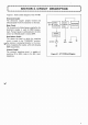
Figure 11 shows a block diagram of the AT-130. Direcltional Coupler The directional coupler samples forward and reflected power from the transceiver to the load. Meter Circuit The forward and reflected power sampled by the directional coupler is used for SWR measurement. Forward power i s calibrated with the CAL control so reflected power is read as SWR. Band Selector Switch This selects the band to which the matching circuit is tuned.
1. General lnformation Your AT-130 has been factory aligned and tested to specification before shipment. Under normal circumstances, it wili operate in accordance with these operating instructions. If your unit fails to work, contact the authorized dealer from which you purchased it for quick, reliable repair. Attempting service without factory authorization can void the unit's warranty. 2.
Circuits and specifications are subject to change for improvement.
Model : Serial AT-130 ......................................................................................................... Date Purchased..................................................... Dealer ........................... ........................................................................................................ A product of TRIO-KENWOOD CORPORATION 1715. 2-chorne. s h l b u y a . sh~buya-KU Tokyo 150.