
user manual


CIRCUIT DESCRIPTION
I
1.
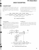
Overview
2.
Circuit Configuration by Frequency
This transceiver is an 800MHz-band (TK-9401,
The receiver
IS
a double-conversion superhet with a
9OOMHz-band (TK-941) EFJ LTRrM trunked-system- first intermediate frequency (IF) of 45.0375MHz (TK-
compatible FM
transceiver
that can be programmed to 940), 39.0375MHz (TK-941) and a second IF of 455kHz.
operate on both LTR and conventional systems.
Incoming signals from the antenna are mixed with the
local signal from the PLL to produce the first IF of
45.0375MHz (TK-940), 39.0375MHz (TK-941).
This is then mixed with the
44.5825MHz (TK-940),
38.5825MHz (TK-941) second local osclllator output to
produce the
455Hz second IF. This is detected to give
the demodulated signal.
The transmit signal frequency is generated by the
PLL VCO, and modulated by the signal from the micro-
phone. It is then amplified by TX amplifier and PA
amplifier, and sent to the antenna.
I
CF
ANT TK-940 TK-941
455kHz
TX 806-825MHz TX 896-902MHz
851 -870MHz 935-941MHz
RX 851-870MHz RX 935-941MHz
1st MIX MCF
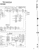
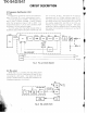
Fig. 1 Frequency configuration
ANT RF
'
IF SYSTEM
-
SW
AMP
805.9625-824.9625MHz.: TK-940
3.
Receiving System
3-1.
RF
unit
An incoming RF signal from the antenna terminal
passes through the antenna switch
(D19, D20, and
D21 are off) and then the
bandpass filter (L9). The
signal is
ampliked by RF amplifier 024, and passes
through the
bandpass filter (L6) again. The resulting
signal goes to the
flrst mixer (021), where it is mixed
with the first local oscillator signal output from the
frequency synthesizer to produce the first IF
45.0375MHz (TK-9401, 39.0375MHz (TK-941).
3-2.
IF
unit
The flrst IF s~gnal then passes through a four-pole
mono~thlc crystal flter (XFI
The s~gnal 1s ampllfled by
flrst IF amplrf~er 016 and goes to the second IF unlt
The second IF unit cons~sts of an IF system IC
(IC~)
and the second mlxer, second local osclllator, second
IF
fllter, and FlV detector, tC7 mlxes the slgnal Input to
~t w~th the 44 5825MHriiTK-940), 38 5825MHz (TK-
941) second local osclllator output #f the clystal
osclilator (X2) to produce the second IF
c'
'55kk
The 455kHz slgnal then goes throug
55khL ce-
ramic filter
CFI, is amplifl 5y the Ilm ampllfler,
demodulated by the quac re FM de or (In the
same
IC),
and output to tht elve audlo
,
lpl~f~er
AF
AMP
MIC
AMP
--
S P
A
45.0375MHz
:
TK-940
-
TK-940 TK-941
806-825MHz 896-902MHz
851-870MHz 935-941MHz
I
PLL
VCO
44.5825MHz
:
TK-940
39.0375MHz
:
TK-941
38.5825MHz
:
TK-941
-
MIC
AMP