
Duel-fuel Double Oven Cooker Instructions for use


42
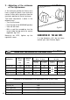
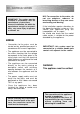
TABLE FOR THE CHOICE OF THE INJECTORS
Cat: II 2H3+
GB
INCREASE OF AIR NECESSARY FOR GAS COMBUSTION (2 m
3
/h x kW)
BURNERS Air necessary for combustion [m
3
/h]
Auxiliary (A) 2,00
Semi-rapid (SR) 3,50
Rapid (R) 6,00
Triple-ring 7,00
G 30 - 28-30 mbar G 20
BURNERS G31- 37 mbar 20 mbar
Auxiliary (A) 1,00 0,30 27 50 72 (X)
Semi-rapid (SR) 1,75 0,45 32 65 97 (Z)
Rapid (R) 3,00 0,75 42 85 115 (Y)
Triple-ring (TR) 3,50 1,50 65 95 135 (T)
Nominal
Power
[kW]
Reduced
Power
[kW]
Ø injector
[1/100 mm]
By-pass
[1/100 mm]
Ø injector
[1/100 mm]
By-pass
[1/100 mm]
adjustable
LUBRICATION OF THE GAS TAPS
If a tap becomes stiff, do not force;
contact your local Service Agent.
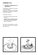
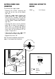
2 - Adjusting of the minimum
of the top burners
In the minimum position the flame must
have a length of about 4 mm and must
remain lit even with a quick turn from the
maximum position to that of minimum.
The flame adjustment is done in the
following way:
– Turn on the burner
– Tum the tap to the MINIMUM position
– Take off the knob
– With a small flat screwdriver turn the
screw inside the tap rod to the correct
regulation (fig. 9.5).
Normally for LPG, tighten up the
regulation screw.
Fig. 9.5