GPS NAVIGATION SYSTEM DNX SERIES DNX5260BT MONITOR WITH DVD RECEIVER DDX SERIES DDX5026 DDX5056 INSTALLATION MANUAL © B54-4763-00/00 (EW/QW) B54-4763-00_00_DNX5_E_En_r1.indd 1 09.11.
Accessories 1 ..........1 2* Installation Procedure *Accessory of DNX5260BT. † This accessory is used when connecting an external device to AV-IN jack on the front panel of this unit. For how to use this accessory, refer to the instruction manual of this unit. ..........1 3* 1. To prevent short circuits, remove the key from the ignition and disconnect the - terminal of the battery. 2. Make the proper input and output wire connections for each unit. 3. Connect the wire on the wiring harness. 4.
¤ • Mounting and wiring this product requires skills and experience. For safety’s sake, leave the mounting and wiring work to professionals. • Make sure to ground the unit to a negative 12V DC power supply. • Do not install the unit in a spot exposed to direct sunlight or excessive heat or humidity. Also avoid places with too much dust or the possibility of water splashing. • Do not use your own screws. Use only the screws provided. If you use the wrong screws, you could damage the unit.
Connection Connector Function Guide Pin Numbers for ISO Connectors External Power Connector A-4 A-5 A-6 A-7 A-8 Speaker Connector B-1 B-2 B-3 B-4 B-5 B-6 B-7 B-8 Cable Colour Functions Yellow Blue/White Orange/White Red Black Battery Power Control Dimmer Ignition (ACC) Earth (Ground) Connection Purple Purple/Black Gray Gray/Black White White/Black Green Green/Black Rear Right (+) Rear Right (–) Front Right (+) Front Right (–) Front Left (+) Front Left (–) Rear Left (+) Rear Left (–) Connector A Ante
Bluetooth Microphone (Accessory 2) (see page 8) GPS Antenna (Accessory 3) (see page 8) FUSE ( 15A ) Accessory 1 2WARNING Connecting the ISO Connector The pin arrangement for the ISO connectors depends on the type of vehicle you drive. Make sure to make the proper connections to prevent damage to the unit. The default connection for the wiring harness is described in 1 below. If the ISO connector pins are set as described in 2, make the connection as illustrated.
System Connection USB terminal USB device (commercially available) Rear View Camera input • Visual input (Yellow) Audio/Visual output • Visual output (Yellow) • Audio left output (White) • Audio right output (Red) Visual input (iPod/AV input 2 switchable) Resistance-free mini plug (3.5φ) Audio input (iPod/AV input 2 switchable) Resistance-free stereo type mini plug (3.
Optional Accessory Connection iPod (commercially available) KCA-iP301V (Optional Accessory) Audio Output (Black) Visual Output (Yellow) (DDX5026/ DDX5056 only) USB terminal Navigation System (Optional Accessory) Connection cable (Included in the Navigation System) KCA-BT200 (Optional Accessory) input (DDX5026/ DDX5056 only) TV Tuner (Optional Accessory) units that can be connected ⁄ Navigation to this unit.
Installing the GPS Antenna (DNX5260BT only) Installing the Microphone Unit (DNX5260BT only) GPS antenna is installed inside of the car. It should be installed as horizontally as possible to allow easy reception of the GPS satellite signals. To mount the GPS antenna inside your vehicle: 1. Clean your dashboard or other surface. 2. Peel the backing off of the adhesive on the bottom of the metal plate (accessory 4). 3.
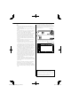
Installation for Monitor/Player Unit Installing the Escutcheon Installing the Monitor/Player Unit 1. Attach accessory 5 to the unit. Bend the tabs of the mounting sleeve with a screwdriver or similar utensil and attach it in place. Accessory 5 ⁄ Make sure that the unit is installed securely in place. If the unit is unstable, it may malfunction (eg, the sound may skip). English | B54-4763-00_00_DNX5_E_En_r1.indd 9 9 09.11.
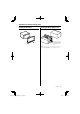
Removing Monitor/Player Unit Removing the Hard Rubber Frame (escutcheon) 1. Engage the catch pins on the removal tool 6 and remove the two locks on the lower level. Lower the frame and pull it forward as shown in the figure. Removing the Unit 1. Remove the hard rubber frame by referring to the removal procedure in the section . 2. Insert the two removal tools 6 deeply into the slots on each side, as shown.
English | B54-4763-00_00_DNX5_E_En_r1.indd 11 11 09.11.
B54-4763-00_00_DNX5_E_En_r1.indd 12 09.11.