GPS NAVIGATION SYSTEM DNX SERIES DNX7360BT DNX7360BTM MONITOR WITH DVD RECEIVER DDX SERIES DDX7036BT DDX7036BTM INSTALLATION MANUAL © B54-4778-00/00 (MW/M2W/XW)
Accessories 1 Installation Procedure 9 ..........1 2 ..........6 0 ..........1 ..........1 3 ! ..........1 4 ..........1 @ ..........1 5 6 ..........1 DNX7360BT, DNX7360BTM only ..........1 $ ..........1 7 DNX7360BT, DNX7360BTM only ..........1 • If you connect the ignition wire (red) and the battery wire (yellow) to the car chassis (ground), you may cause a short circuit, that in turn may start a fire.
product is first powered on works properly, the front panel will automatically move into the position (initial setting angle) shown in (Fig. 2). (Fig. 1) (Fig. 2) After the Installation After the installation, perform the Initial Setup by referring to the instruction manual. ¤ • Mounting and wiring this product requires skills and experience. For safety’s sake, leave the mounting and wiring work to professionals. • Make sure to ground the unit to a negative 12V DC power supply.
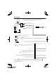
Connection connect the ignition wire (red) and the battery wire (yellow) ¤ Iftoyou the car chassis (ground), you may cause a short circuit, that in Ignition key switch turn may start a fire. Always connect those wires to the power source running through the fuse box. ACC Ignition wire (Red) Battery wire (Yellow) Car fuse box (Main fuse) Antenna Cord Car fuse box A Ground wire (Black) (To car chassis) FM/AM antenna input A Battery to the vehicle's parking brake ⁄ Connect detection switch harness.
Bluetooth Microphone (Accessory !) (see page 8) Cooling fan GPS Antenna (Accessory #) (DNX7360BT, DNX7360BTM only) (see page 8) FUSE (15A ) Reverse sensor wire (Purple/White) REVERSE Accessory 1 To front left speaker White/Black White + Steering remote control input (Light Blue/Yellow) REMOTE CONT STEERING WHEEL REMOTE INPUT Dimmer control wire (Orange/White) To front right speaker Gray/Black Gray + ILLUMI Mute control wire (Brown) MUTE To rear left speaker Green/Black + Green Motor antenna
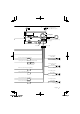
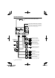
System Connection USB device or iPod (commercially available) USB terminal Audio input (iPod/AV Input 2 switchable) Resistance-free stereo type mini plug (3.5φ) Visual input (iPod/AV Input 2 switchable) Resistance-free mini plug (3.
Optional Accessory Connection iPod (commercially available) KCA-iP301V (Optional Accessory) Visual Output (Yellow) Audio Output (Black) DDX7036BT, DDX7036BTM only USB terminal TV Tuner (Optional Accessory) USB terminal Navigation System (Optional Accessory) Connection cable (Included in the Navigation System) TO MONITOR UNIT Connection cable (Included in the TV tuner) units that can be connected to this unit.
Installing the Microphone Unit Installing the GPS Antenna (DNX7360BT, DNX7360BTM only) 1. Check the installation position of the microphone (accessory !). 2. Remove oil and other dirt from the installation surface. 3. Install the microphone. 4. Wire the microphone cable up to the unit with it secured at several positions using tape or the like. GPS antenna is installed inside of the car. It should be installed as horizontally as possible to allow easy reception of the GPS satellite signals.
Installing the Escutcheon For General Motors For Toyota/Scion 1. Cut out accessory 6 to meet the shape of the opening of the center console. 2. Attach accessory 6 to the unit. 1. Cut out accessory 6 as illustrated. Cutting line Cut out to meet the shape of the opening in the vehicle. Accessory 6 Accessory 6 For Volkswagen 1. Attach accessory 0 to the unit. 2. Fold double-sided adhesive (accessory 7) along the slit and attach it to accessory 6 cut-out against the center rib as illustrated.
Installation for Monitor/Player Unit Installation the Monitor/Player unit Attaching the monitor panel Accessory @ Bend the tabs of the mounting sleeve with a screwdriver or similar utensil and attach it in place. ⁄ • Make sure that the unit is installed securely in place. If the unit is unstable, it may malfunction (eg, the sound may skip). Installation on Toyota, Nissan or Mitsubishi Car using Brackets Hold the monitor panel securely so as not to drop it accidentally.
Removing Monitor/Player Unit Removing the Hard Rubber Frame (escutcheon) 1. Engage the catch pins on the removal tool 5 and remove the two locks on the lower level. Lower the frame and pull it forward as shown in the figure. Removing the Unit 1. Remove the hard rubber frame by referring to the removal procedure in the section . 2. Insert the two removal tools 5 deeply into the slots on each side, as shown. Accessory 5 Accessory 5 Catch Lock ⁄ 3.