KAC-X812D SUBWOOFER POWER AMPLIFIER 7 page 2-9 INSTRUCTION MANUAL AMPLIFICATEUR DE PUISSANCE DU SUBWOOFER 7 page 10-17 MODE D’EMPLOI AMPLIFICADOR DE POTENCIA DEL ALTAVOZ DE SONIDO ENVOLVENTE 7 página 18-25 MANUAL DE INSTRUCCIONES Take the time to read through this instruction manual. Familiarity with installation and operation procedures will help you obtain the best performance from your new power amplifier.
Safety precautions 2 WARNING To prevent injury or fire, take the following precautions: • When extending the ignition, battery, or ground wires, make sure to use automotive-grade wires or other wires with a 8 mm² (AWG 8) or more to prevent wire deterioration and damage to the wire coating. • To prevent a short circuit, never put or leave any metallic objects (such as coins or metal tools) inside the unit.
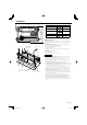
Installation Accessories 386 mm 372 mm 1 265 mm VOLT CURR 252 mm FAN TEMP 157 mm Part name External View Self-tapping screws (ø5 × 18 mm) Hexagon socket head cap screw (M4 × 8 mm) Number of Items 4 4 Cover 1 Terminal cover (Power terminal) 1 Hexagon Wrench 1 150 100 2 0.5 70 3 4 (MIN)5 0.2(MAX) 50 INPUT SENSITIVITY(V) 200 40 200 LPF FREQUENCY(Hz) B.R.
Connection * Commercially available parts 2 WARNING CENTER UNIT (CD receiver, etc.) To prevent fire caused by a short in the wiring, connect a fusible link or breaker nearby the battery’s positive terminal. RCA cable ground terminal 2 CAUTION RCA cable* • If sound is not output normally, immediately turn power off and check connections. • Be sure to turn the power off before changing the setting of any switch.
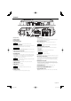
Controls 30 30 4 5 6 2 3 7 8 90 1 1 2 3 4 5 6 # 1 Fuse (30 A × 2) 2 Battery terminal 3 Ground terminal 4 Power control terminal Controls the unit ON/OFF. NOTE Controls the unit power. Be sure to connect it with all the systems. 5 Speaker output terminals As this unit accepts speakers with a minimum impedance of 1 ohm, connect speakers with 1-ohm or higher impedance to these terminals. 2 CAUTION The rated input of the speakers should be no less than the maximum output of the amplifier.
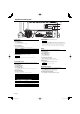
Amplifier Control System Indicator FAN VOLT TEMP CURR MENU 2/3 Display mode 4 Exit Menu mode You can set up the display items as follows: Press the [MENU] button for at least 1 second. NOTE 1 Enter Menu mode Press the [MENU] button. "VOLT"/"CURR"/"TEMP"/"FAN" is displayed. 2 Select a display item Press the [2] or [3] button. The display items are switched in the following sequence. Display "VOLT" "CURR" "TEMP" "FAN" Information Indicates the source voltage (V).
Control an Amp from Center Unit Messages that may be displayed on the Center Unit You can control the sound by controlling amplifiers from the Center Unit. When you are selecting an item with the Amp Control, an error status of the amplifier is displayed on the Center Unit. 1 Enter AMP Control mode Select the AMP Control mode by following the procedure given on the Operation Manual of the Center Unit.
Band Reject Filter The acoustic properties of vehicle compartment tend to cause oscillation due to resonance or unclearness of sound due to standing waves at certain frequencies. The band reject filter can solve the problems of resonance or unclear sound with minimum influence on the sound quality because it eliminates only the frequencies causing resonance or standing waves. ■ Adjustment method: 0 dB The band reject filter cuts only the limited frequencies to minimize influence on the sound quality.
Specifications Specifications subject to change without notice. Audio Section Max Power Output ........................................................................................................................................................................................................................................ 1600 W Rated Power Output (+B = 12.0 V) (4 Ω) (20 Hz – 200 Hz, 0.5 % THD) ..............................................................................................................
Précautions de sécurité 2AVERTISSEMENT Pour éviter toute blessure et/ou incendie, veuillez prendre les précautions suivantes: • Si vous prolongez un câble de batterie ou de masse, assurez vous d'utiliser un câble pour automobile ou un câble avec une section de 8 mm² (AWG8) afin d'éviter tous risques de détérioration ou d'endommagement du revêtement des câbles.
Installation Accessoires 386 mm 372 mm Nom de la pièce 1 150 265 mm VOLT CURR 252 mm FAN TEMP 157 mm Vis taraudeuses (ø5 × 18 mm) Vis d’assemblage à six pans creux (M4 × 8 mm) Vue extérieure Quantité 4 4 Couvercle 1 Cache de bornier (Borne d’alimentation) 1 Clé polygonale 1 100 2 0.5 70 3 4 (MIN)5 0.2(MAX) 50 INPUT SENSITIVITY(V) 200 40 200 LPF FREQUENCY(Hz) B.R.
Raccordements * disponible dans le commerce 2AVERTISSEMENT Unité centrale (récepteur/ lecteur de CD, etc.) Pour éviter tout incendie dû à un court-circuit, insérer un fusible ou un coupecircuit à proximité de la borne de la batterie. Borne de masse pour câble RCA 2ATTENTION • En cas d'anomalie, mettre immédiatement l'appareil hors tension et vérifier tous les raccordements. • Veiller à mettre l'appareil hors tension avant de changer la position des commutateurs.
Contrôles 30 30 4 5 6 2 3 7 8 90 1 1 2 3 4 # 1 FUSIBLE (30 A × 2) 2 Borne BATT (alimentation) 3 Borne GND (masse) 4 Borne P.CON (fil de commande d’alimentation) Commande l’unité ON/OFF. REMARQUE Commande l’unité d’alimentation. Assurez-vous de le connecter à l’ensemble des différents systèmes.
Système de commande d’amplificateur Indicateur FAN VOLT TEMP CURR MENU 2/3 Mode d’affichage Vous pouvez régler les éléments de l’affichage comme suit : 4 Sortez du mode menu Appuyez sur la touche [MENU] pendant au moins 1 seconde. REMARQUE 1 Entrer dans le mode menu Appuyez sur la touche [MENU]. "VOLT"/"CURR"/"TEMP"/"FAN" est affiché. 2 Sélectionner un élément de l’affichage Appuyez sur la touche [2] ou [3]. Les éléments de l’affichage sont commutés dans l’ordre suivant.
Contrôle d’un ampli à partir de l’unité centrale Messages pouvant s’afficher sur l’unité centrale Vous pouvez contrôler le son en contrôlant les amplificateurs à partir de l’unité centrale. Lorsque vous sélectionnez un élément avec la commande d’ampli, un état d’erreur de l’amplificateur s’affiche sur l’unité centrale. 1 Entrez en mode de commande AMP Sélectionnez le mode de commande AMP en suivant la procédure donnée dans le mode d’emploi de l’unité centrale.
Filtre coupe bande (B.R.F.) Pour certaines fréquences, les caractéristiques de l'habitacle du véhicule sont telles que des résonances parasites et des ondes stationnaires peuvent prendre naissance. En n'éliminant que les fréquences responsables des résonances et des ondes stationnaires, le filtre coupe-bande peut supprimer ces phénomènes gênants sans altérer de façon significative la qualité des sons.
Spécifications Les spécifications sont sujettes à modifications sans préavis. Section audio Puissance de sortie max. ............................................................................................................................................................................................................................ 1600 W Puissance de sortie norminale (+B = 12,0 V) (4 Ω) (20 Hz – 200 Hz, 0,5 % THD) .........................................................................................
Precauciones de seguridad 2ADVERTENCIA Para evitar el riesgo de lesiones y/o fuego, observe las siguientes precauciones: • Cuando extienda los cables de la batería o de masa, asegúrese de utilizar cables para automóviles u otros cables que tengan un área de 8 mm² (AWG8) o más, para evitar el deterioro del cable y daños en su revestimiento. • Para evitar cortocircuitos, nunca coloque ni deje objetos metálicos (por ejemplo, monedas o herramientas metálicas) dentro de la unidad.
Instalación Accesorios 386 mm 372 mm Nombre de pieza 1 265 mm VOLT CURR 252 mm FAN TEMP 157 mm Tornillo autorroscantes (ø5 × 18 mm) Tornillo de cabeza hexagonal (M4 × 8 mm) 150 Vista exterior Unidades 4 4 Tapa 1 Cubierta de terminales (Terminal del cable de alimentación) 1 Llave hexagonal 1 100 2 0.5 70 3 4 (MIN)5 0.2(MAX) 50 INPUT SENSITIVITY(V) 200 40 200 LPF FREQUENCY(Hz) B.R.
Conexiones * pieza de venta en el comercio especializado 2ADVERTENCIA APARATO CENTRAL (reproductor de discos compactos, etc.) Para evitar incendios producidos por cortocircuitos en el cableado, conecte un fusible o cortacircuito entre la batería y los terminales de la batería. Terminal del cable de masa del cable RCA Cable RCA* 2PRECAUCIÓN • Si el sonido no sale normalmente, desconecte inmediatamente la alimentación y compruebe las conexiones.
Controles 30 30 4 5 6 2 3 7 8 90 1 1 2 3 4 5 6 # 1 FUSIBLE (30 A × 2) 2 Terminal BATT (alimentación) 3 Terminal GND (tierra) 4 Terminal del control de corriente (P.CON) Controla la CONEXIÓN / DESCONEXIÓN de la unidad. NOTA Controla la potencia de la unidad. Asegúrese de conectarlo con todos los sistemas. 5 Terminales SPEAKER OUTPUT Como este aparto acepta altavoces con una impedancia mínima de 1 ohmio, conecte altavoces con una impedancia de 1 ohmio o más a estos terminales.
Sistema de control del amplificador Indicador FAN VOLT TEMP CURR MENU 2/3 Modo de visualización Es posible configurar los elementos de ajuste de la siguiente manera: 4 Salir del modo de menú Pulse el botón [MENU] durante al menos 1 segundo. NOTA 1 Acceda al modo de menú Pulse el botón [MENU]. Se visualiza "VOLT"/"CURR"/"TEMP"/"FAN". 2 Seleccione un elemento de visualización. Pulse el botón [2] o [3]. Los elementos de visualización cambian en la frecuencia siguiente.
Control de un amplificador desde la unidad central Mensajes que se pueden visualizar en la unidad central Es posible controlar el sonido al controlar los amplificadores desde la unidad central. Cuando seleccione un elemento con el control del amplificador, se visualizará un estado de error del amplificador en la unidad central. 1 Acceda al modo de control AMP Seleccione el modo de control AMP siguiendo el procedimiento explicado en el manual de funcionamiento de la unidad central.
Filtro de rechazo de banda (B.R.F.) Las propiedades acústicas del compartimiento del vehículo tienden a causar oscilaciones debido a la resonancia o falta de claridad del sonido causada por las ondas estacionarias en ciertas frecuencias. El filtro de rechazo de banda puede resolver los problemas de resonancia o sonido poco claro causando una influencia mínima en la calidad del sonido, porque sólo elimina las frecuencias que causan la resonancia o las ondas estacionarias.
Especificaciones Especificaciones sujetas a cambios sin previo aviso. Sección de audio Máxima potencia de salida ....................................................................................................................................................................................................................... 1600 W Salida de potencia nominal (+B = 12,0 V) (4 Ω) (20 Hz – 200 Hz, 0,5 % de distorsión armónica total) ............................................................................
B64-3393-00_00.indb 26 05.11.
B64-3393-00_00.indb 27 05.11.
B64-3393-00_00.indb 28 05.11.