STEREO/BRIDGEABLE POWER AMPLIFIER KAC-6202 INSTRUCTION MANUAL © B64-3043-00/00 (MV) B64-3043-00-00̲M̲English.indd 1 04.12.
Safety precautions 2WARNING To prevent injury or fire, take the following precautions: • When extending the ignition, battery, or ground wires, make sure to use automotive-grade wires or other wires with a 5 mm² (AWG 10) or more to prevent wire deterioration and damage to the wire coating. • To prevent a short circuit, never put or leave any metallic objects (such as coins or metal tools) inside the unit.
Installation Self-tapping screw (ø4 × 16 mm) 330 mm 231 mm 227 mm 232 mm 242 mm Ø4.6 Installation board, etc. (thickness : 15 mm or more) 2CAUTION • Do not install in the below locations; (Unstable location, In a location that interferes with driving, In a location that gets wet, In a dusty location, In a place that gets hot, In a place that gets direct sunlight, In a location that gets hit by hot air) • Do not install the unit under the carpet.
Controls / Indicator 3 1 2 3 1 FILTER switch 40 30 20 10 (W) 4 4 OPERATION switch This switch allows to apply high-pass or low-pass filtering to the speaker outputs. This switch is used to select the operation mode of the amplifier. • HPF (High-Pass Filter) position: • STEREO position: The filter outputs the band of higher frequencies than the frequency set with the FILTER FREQUENCY control. • OFF position: The entire bandwidth is output without filtering.
5 Power indicator When the power is turned on, the Power indicator lights. If the Power indicator does not light when the power is turned on, the protection function may be activated. Check whether there is any indication of trouble. ■ The protection function is activated in the following situations: This unit is equipped with a protection function for protecting this unit and your speakers from various accidents or problems that can occur.
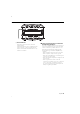
Connection ■ Terminal names 25 6 78 9 0 ! 6 Fuse (25 A) 7 Battery terminal 8 Ground terminal 9 Power control terminal Controls the unit ON/OFF. NOTE Controls the unit power. Be sure to connect it with all the systems. 0 Speaker output terminals • Stereo Connections: When you wish to use the unit as a stereo amplifier, stereo connections are used. The speakers to be connected should have an impedance of 2Ω or greater.
■ Installation procedure ■ Wiring Since there are large variety of settings and connections possible according to applications, read the instruction manual well to select the proper setting and connection. 1. Remove the ignition key and disconnect the negative - terminal of the battery to prevent short circuits. 2. Set the unit according to the intended usage. 3. Connect the input and output wires of the units. 4. Connect the speaker wires. 5.
Connection ■ RCA cable or Speaker level input connection (RCA cable Connections) ! RCA cable* CENTER UNIT (CD receiver, etc.) @ Power control wire (Blue/ White) @ D GN Left input Right input RCA cable ground terminal Speaker level input cable (Speaker level input Connections) Cable Color of the connector White Left White/Black Gray Right Gray/Black Genuine-accessory car stereo (No line output center unit etc.) # Car fuse box Battery ACC 8 English B64-3043-00-00̲M̲English.indd 8 04.12.
* Commercially available parts ■ Speaker wire connection (Stereo Connections) 0 0 Left speaker Right speaker Lead terminal* 25 (Bridged Connections) 0 Speaker (Bridged) 25 ■ Power wire connection 25 789 Lead terminal* Terminal cover Power control wire Battery wire* Ground wire* Protective Fuse* Battery English B64-3043-00-00̲M̲English.indd 9 9 04.12.
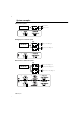
System examples ■ 2-channel system CENTER UNIT L L Left speaker R R Right speaker L L Left speaker (Bridged) R R 4 1 ■ High-power 2-channel system ¡ L CENTER UNIT R L L R R Right speaker (Bridged) ™ ¡ ™ 1 4 ■ 2-channel + Subwoofer system ¡ CENTER UNIT L L Left speaker (High pass) R R Right speaker (High pass) L L Subwoofer (L + R) (Bridged) R R ™ 1 2 4 1 2 4 ¡ ™ 10 English B64-3043-00-00̲M̲English.indd 10 04.12.
■ Tri-mode L C CENTER UNIT L L R R (High pass) Subwoofer (L + R) (Bridged) C 4 1 ●Principle of Tri-mode Method of frequency band division using a coil and capacitor…in case of 6dB/oct. slope Coil (L): Passes low frequencies and blocks high frequencies. (Low pass) Capacitor (C): Passes high frequencies and blocks low frequencies.
Troubleshooting Guide What might appear to be a malfunction in your unit may just be the result of slight misoperation or miswiring. Before calling service, first check the following table for possible problems. PROBLEM POSSIBLE CAUSE SOLUTION No sound. • Input (or output) cables are • Connect the input (or output) (No sound from one side.) disconnected. cables. (Blown fuse.) • Protection circuit may be activated. • Check connections by referring to . • Volume is too high.
Specifications Specifications subject to change without notice. Audio Section Max Power Output ...............................................................................................................................................................................................400 W Rated Power Output Normal (4 Ω) (20 Hz – 20 kHz, 0.08 % THD) ...................................................................................................................................
B64-3043-00-00̲M̲English.indd 14 04.12.