KAC-648 4-CHANNEL POWER AMPLIFIER INSTRUCTION MANUAL B64-1364-00 (EM)
Safety precautions 2WARNING To prevent injury and/or fire, take the following precautions: • When extending the battery or ground cables, make sure to use automotive-grade cables or other cables with an area of 3 mm 2 (AWG12) or more to prevent cable deterioration and damage to the cable coating. • To prevent short circuits, never put or leave any metallic objects (e.g., coins or metal tools) inside the unit.
Installation procedure 1. Remove the ignition key and disconnect the negative - terminal of the battery to prevent short circuits. 2. Set the unit according to the intended usage. 3. Connect the input and output cables of the units. 4. Connect the speaker cables. 5. Connect the power cable, power control cable and grounding cable following this order. 6. Install the unit in the car. 7. Connect the negative - terminal of the battery.
Controls This is a 4 channel amplifier including 2 stereo amplifiers in a body. One amplifier is referred to as amplifier A and the other is amplifier B. This unit is compatible with a large variety of systems by combining the switches and functions described in the following. 5 POWER IN FUSE(25A) SPEAKER OUTPUT GND SPEAKER LEVEL INPUT LEFT RIGHT BRIDGED LEFT RIGHT A A P.
independently according to the setting of this switch. ! LINE OUT terminal These jacks output respectively the signals input to amplifiers A and B. They always output the stereo signals regardless of the position of the OPERATION switch. • STEREO position: The amplifier can be used as a stereo amplifier.
System examples ■ High-pass + Subwoofer system 1.0 MONO(Lch) 0.3 MIN INPUT SELECTOR A B A MAX INPUT SENSITIVITY(V) CONTROL A CONTROL B R CENTER UNIT OPERATION L STEREO R 0.5 (Lch) MONO 0.3 MIN MAX A L (High pass) R 1.0 FILTER OFF HPF LPF L 0.5 OPERATION Switch setting B L LINE R OUT INPUT SENSITIVITY(V) BRIDGED FILTER OFF STEREO HPF LPF Subwoofer (L + R) (Bridged) 0.5 OPERATION MONO(Lch) 0.3 MIN INPUT SELECTOR A B A INPUT SENSITIVITY(V) CONTROL A CONTROL B R 1.
Connection ■ Power cable connection 2WARNING To prevent fire caused by a short in the wiring, connect a fusible link or breaker nearby the battery’s positive terminal. POWER IN FUSE(25A) SPEAKER OUTPUT GND BATT BRIDGED LEFT RIGHT SPEAKER LEVEL INPUT LEFT RIGHT A A P.
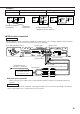
Connection ■ Speakers cable connection (Stereo Connections) Front Left speaker Lead terminal (Commercially available parts) Front Right speaker ED IDG BR A Right output A Left output POWER IN FUSE(25A) SPEAKER OUTPUT GND BATT BRIDGED LEFT RIGHT LE RIG HT FT SPEAKER LEVEL INPUT LEFT RIGHT A A P.
Examples: Stereo Connections (4Ω) 50 W or greater Model KAC-648 50W (4Ω) 50W (4Ω) 50W (2Ω) 50W (4Ω) 25W (8Ω) 50W (4Ω) 50W (2Ω) 4Ω Maximum output of the amplifier Bridged Connections (4Ω) 140 W or greater 4Ω 4Ω Combined impedance 25W (8Ω) Rated input power and impedance of the speakers ■ RCA cable connection 2CAUTION Do not connect cables and leads to both RCA cable input jacks and the speaker input terminals simultaneously, for this may cause malfunction or damage.
Connection ■ Speaker level input connection Connect the unit by inserting it in the connection between the genuine-accessory car stereo and speakers. 2CAUTION Do not connect cables and leads to both RCA cable input jacks and the speaker input terminals simultaneously, for this may cause malfunction or damage. To Power control (REMOTE) terminal A Left input POWER IN FUSE(25A) SPEAKER OUTPUT GND BATT A Right input BRIDGED LEFT RIGHT SPEAKER LEVEL INPUT LEFT RIGHT A A P.
Troubleshooting Guide What might appear to be a malfunction in your unit may just be the result of slight misoperation or miswiring. Before calling service, first check the following table for possible problems. PROBLEM POSSIBLE CAUSE SOLUTION No sound. (No sound from one side.) • Input (or output) cables are • Connect the input (or output) disconnected. cables. • Protection circuit may be • Check connections by referring activated. to "Protection function".
Specifications Specifications subject to change without notice. Audio Section Max Power Output (4 Ω) 4 Channel Mode.................................................................................................................50 W × 4 3 Channel Mode ............................................................................................50 W × 2 + 140 W × 1 2 Channel Mode...............................................................................................................