4-CHANNEL POWER AMPLIFIER LAC-943 INSTRUCTION MANUAL KEN WOOD CORPORATION Take the time to read through this instruction manual. Familiarity with installation and operation procedures will help you obtain the best performance from your new 4-channel power amplifier. For your records Record the serial number, found on the back of the uniting the spaces designated on the warranty card, and in the space provided below.
SAFETY PRECAUTIONS D A WARNING To Prevent fires and avoid personal injury in case of accidents. & When extending the Power supply, or Ground lead, avoid short circuits by using & mm? (WAGS) or Larger automotive grade cable. o Check to be sure that no metal objects (tools, needles, coins) are left inside the unit. & If you smell or see smoke, disconnect the unit immediately and consult your KEN WOOD dealer. Continued use can cruse a fire or permanent damage to the unit.
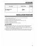
ACCESSORY " Number Part name External View of stems Self-tapping screw 18mm)} INSTALLATION PROCEDURE 1. Before starting installation, disconnect the © terminal of the battery. This will prevent short circuits, . Connect the Power cord. {ez P.9) . Install the uniting the car. ez P16} CAUTION . Connect the Input and Output leads. G . Connect the Ground cord to the metal body of the car. (= P.9) . Connect the negative © terminal of the battery. & A short circuit may cause a blown fuse.
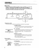
CONTROLS B LAC-943 This is a 4-channel amplifier including 2 stereo amplifiers in a body. One amplifier is referred to as amplifier A and the other is amplifier B, This unit is compatible with a large variety of systems by combining the switches and functions described in the following. Amplifier A Amplifier B {D Operation switch This switch allows to select the amplification method of input signals. « STEREO position: The input left and right signals are amplified separately.
@Filter switch This switch allows 1o switch the filter function to High pass filler ON. Low pass filter ON or to OFF. OFF : HPFE'LP_F HPF {High pass filter) . LPF {(Low pass filter) position
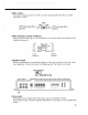
CONTROLS < Amplifier A Amplifier B (D Input sensitivity control Adjust the control according to the per-out level of the center unit connected to this unit. When the per-out level of the center units between 800 and 1000 mV, set the input sensitivity control to the 0.3 V position. Center unit per-out Amplifier level i ti vi Volume Volume input sensitivity decreases %35 increases 200 mV MAX 10 800-1000 mv 03V NN MAX Refer to “SPECIFICATIONS” on the center unit's instruction manual about the Pr-out level.
PROTECTION FUNCTION R — Protection function & This unit is equipped with a protection function for protecting this unit and your speakers from various accidents or problem that can scour. & When the protection function activates, the unit stops operating ard the power indicator lights gran to indicate that the protection function is activated. . The protection function activates in the following situations: & When a speaker output contacts ground.
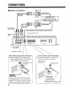
CONNECTIONS M System connection {Optional} {8 Left (Mona} input (White) (Bl Right input {Red} Power control cord {Commercially available parts) Power control terminal Right cutout {Red) Lat output (White) CENTER UNIT {Cassette/CD receiver, Lat output | Graphic equalizer etc.) (White) Right output {Red) & Lent (Mossy ? input {White) | | Right input (Red} i ACA cable ground cord connection & When using an RCA cable with a ground cord attached, connect the ground cord to this terminal.
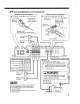
M Power and Speakers cord connection Speaker cord connection # Connect the speaker cords to these terminals. Speaker terminal Lead terminal (Commercially available parts) Speaker cord {Commercially available parts} {a] Front Right speaker @& Front Left speaker 280 Ground terminal Power source connection e Connect the power cord and ground cord to the corresponding terminals.
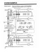
SYSTEM EXAMPLES When two LAC-943 are used as 2-channel amplifiers, a System example 1. high power 4-channel amplifier can be configuration. Power control terminal Front Right speaker RCA cable {Optional} ens) T ,I-l U {A Left Wont] & @ Frost input {White] Left speaker Power control cord B Le{' {Mono} it {Whit Input W Rte) H Switch setting Right output Left put Put INPUT {Red) {White} PERFORATION [ SELECTOR OPERATION Bl e e Front output b e CENTER UNIT {Cassette/CD receiver, —=e Graphic equalizer etc.) ..
System example 2. A multi-amplifier system can be formed with a single unit. With amplifier A, use the high pass filter and connect full range speakers to output 90 Hz or more from them. With amplifier B, use the low pass filter and connect sub woofers to output 90 Hz or less from them. Right cutout {Red} CENTER UNIT {Cassette/CD receiver, Graphic equalizer etc.
SYSTEM EXAMPLES System example 3. Using the Line output jacks, & sub woofer is added to the system to output 90 Hz or less from them. RCA cable {Optional} & Left {Mono} input {White} Front full-range speaker Right {Low cut} Left output {White} ®00® Right cutout {Red} A Right input ted} BN aar (4] Left {(Mono) ° input (White {Low cut) Right input (Red) Lot RCA cabin (Optional) ( W Switch setting SPLINT OPERATION (Bl SELECTOR OPERATION VoG B 1B Lent BH.
Right output {Red) CENTER UNIT {Cassette/CD receiver, Graphic equalizer, etc) Rear output Left cutout {White} Left output (White} Front output Right cutout {Red} Power control cord {Commercially available parts} Left (Mona) Input (White} Power control terminal etc. {Optional} Right input (Rey Sub woofer {Monaural) B Set the Low pass filter switch to ON and set the frequency control! to the 90 Hz position.
TREE-MODE Only using coils and capacitors in the stereo 4-channel speaker system [refer below), a sub woofer can be added to the system, < Operation switch setting > « Speaker switch setting > OPERATION SPEAKER STEED ] MONO(L) 40 BRIDGED.22 LR ® Characteristics of coil and capacitor ® Coil {L): Passes low frequencies and blocks high frequencies. {Low pass} # Capacitor [C): Passes high frequencies and blacks low frequencies.
M SYSTEM EXAMPLES # When a sub woofer is added to the rear speaker system @ Amplifier A QL-_; fused for from speakers) Amplifier B {used for rear speakers) L LAC-943 | sleeveless NOTE " Front fl . speakers Rear = Sub woofer 2 . speakers = {Monaural) R N L Using the TREE-MODE PASSIVE CROSSOVER NETWORK * KPX-T120" (Optional} rakes the system’s wiring easier.
INSTALLATION M Installation Self-tapping screw {Accessory} Installation board, ete. {thickness more) NOTE Do rot install the unit under the carpet. Otherwise heat build-up scours and the unit may be damaged.
M Installation location & Since the power amplifier has no pairs which require operation, it can be installed at & position away from the driver's seat without any hindrances. As generally accepted positions for its installation, places such as inside the trunk, etc. can be considered. A CAUTION & Install this unit in a location which allows heat to easily dissipate.
TROUBLESHOOTING GUIDE 0 Often, what appears to be a malfunction is due to user error. Before calling for service, please consult the following table. Symptom Cause Remedy Mo sound, A speaker cord has bloomer Check the speaker cord {Mo sound from one unconnected. connections, side.) The level is too fow The input sensitivity adjust Ag just carriageway referring te tor high). control 18 not sel 10 the correct CONTROL'S, position. The sound quality is 1. The speaker cord is 1, Connect gate speaker bad.