KAC-X650D KAC-PS650D 5-CHANNEL POWER AMPLIFIER 7 page 2-15 INSTRUCTION MANUAL AMPLIFICATEUR DE PUISSANCE 5 CANAUX 7 page 16-29 MODE D’EMPLOI AMPLIFICADOR DE POTENCIA DE 5 CANALES 7 página 30-43 MANUAL DE INSTRUCCIONES Take the time to read through this instruction manual. Familiarity with installation and operation procedures will help you obtain the best performance from your new power amplifier.
Safety precautions 2WARNING To prevent injury or fire, take the following precautions: • When extending the ignition, battery, or ground wires, make sure to use automotivegrade wires or other wires with a 8mm2 (AWG8) or more to prevent wire deterioration and damage to the wire coating. • To prevent a short circuit, never put or leave any metallic objects (such as coins or metal tools) inside the unit.
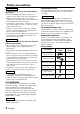
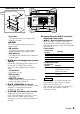
Installation Self-tapping screw (ø5 × 18 mm) Cooling fan : Air inlet Exhaust outlet Hexagon socket head cap screw (M3 × 8 mm) Terminal cover Hexagon Wrench Installation board, etc. (thickness : 15 mm or more) Self-tapping screws (ø3 × 8 mm) Mounting Hardware 1. Install the installation fittings in the unit. 2. Attach the unit. 3. Install the terminal cover.
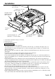
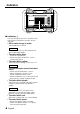
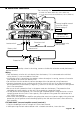
Controls A.CH FILTER OFF HPF B.CH INPUT SELECTOR OPERATION B.M.S. OFF HPF LPF OFF REMOTE +12dB STEREO MONO(Lch) A B A A B A SUB LINE IN B EXT.AMP.CONT. SUB L L R R GND 200 50 A.CH HPF 200 50 B.CH HPF 200 50 B.CH LPF 200 50 SUB.CH LPF FILTER FREQUENCY(Hz) 8 A.CH FILTER OFF HPF B.CH 200 50 A.CH HPF OFF REMOTE +12dB 200 50 B.CH HPF INPUT SELECTOR OPERATION B.M.S. OFF HPF LPF STEREO MONO(Lch) 200 50 B.CH LPF A B A A B SUB 9 0 200 50 SUB.
Removing the cover Hexagon Wrench Tighten Loosen ! • A position: The input for terminal A is output from amplifiers A and B. (AB/SUB) This switch toggles the input signal of amplifier SUB. • AB position: The input for terminals A and B input is mixed and output from amplifier SUB. • SUB position: The input for the SUB terminal is output by amplifier SUB. 3 B.M.S.(Bass management system) switch Bass boost centered on the frequency set by the B.M.S. FREQUENCY control. The B.M.S.
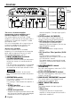
Indicator ! ■ Indicator ! You are notified of the unit’s condition and malfunction (Protection function) by the indicator. • ON or color change in order. When operation is normal NOTE The color you want can be selected with the variable color button. • The color blinks blue – When during operation – When the center unit/B.M.S. switch controls the B.M.S. • The color blinks yellow When the power voltage is less than 11V. NOTE The cause may be one of the below times.
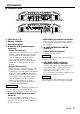
Connection ■ Terminal names POWER IN FUSE(30Ax2) GND BATT. BRIDGED LEFT SPEAKER P.CON OUTPUT RIGHT SUB A 30 30 B SUB @ A.CH FILTER OFF HPF # $ % OPERATION B.M.S. B.CH OFF HPF LPF OFF REMOTE +12dB STEREO MONO(Lch) ^ INPUT SELECTOR A B A A B A SUB & LINE IN B EXT.AMP.CONT. SUB L L R R GND 200 50 A.CH HPF 200 50 B.CH HPF 200 50 B.CH LPF 200 50 SUB.
Connection ■ Installation procedure Since there are large variety of settings and connections possible according to applications, read the instruction manual well to select the proper setting and connection. 1. Remove the ignition key and disconnect the negative - terminal of the battery to prevent short circuits. 2. Set the unit according to the intended usage. 3. Connect the input and output wires of the units. 4. Connect the speaker wires. 5.
■ Power wire connection The connecting wire diameter* • If solid wire: Ø0.4 (AWG 26) – Ø1.2 (AWG 16) • If multi strand wire: Ø0.4 (AWG 26) – Ø1.2 (AWG 16) 11 mm ) A.CH FILTER B.CH INPUT SELECTOR OPERATION B.M.S. OFF HPF LPF OFF HPF OFF REMOTE +12dB STEREO MONO(Lch) A B A A B A SUB LINE IN B EXT.AMP.CONT. SUB L L R R GND 200 50 A.CH HPF 200 50 B.CH HPF 200 50 B.CH LPF 200 50 SUB.CH LPF FILTER FREQUENCY(Hz) External amplifier control wire (Pink / Black) (Refer to page 7) EXT.CONT.
Connection ■ RCA cable connection * : Commercially available parts RCA cable ground terminal ( Left input A.CH FILTER OFF HPF OPERATION B.M.S. B.CH OFF HPF LPF OFF REMOTE +12dB STEREO MONO(Lch) INPUT SELECTOR A B A A B A SUB LINE IN B EXT.AMP.CONT. CENTER UNIT (CD receiver, etc.) SUB L L R R GND 200 50 A.CH HPF 200 50 B.CH HPF 200 50 B.CH LPF 200 50 SUB.
■ Speaker wire connection Front Left speaker Front Right speaker & ^ POWER IN FUSE(30Ax2) BATT. GND SPEAKER P.CON OUTPUT BRIDGED LEFT RIGHT Subwoofer (L + R) SUB A 30 30 B SUB ^ Rear Right speaker Lead terminal* Rear Left speaker (Stereo Connections) (Bridged Connections) Left speaker (Bridged) & ^ POWER IN FUSE(30Ax2) BATT. GND SPEAKER P.
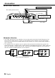
System examples ■ 5-channel system (1) CENTER UNIT L B R 5 7 OPERATION INPUT SELECTOR STEREO MONO(Lch) (2) A B A B SUB CENTER UNIT 5 INPUT SELECTOR OPERATION A B A A B SUB CENTER UNIT 5 INPUT SELECTOR OPERATION A B A A B A B L Front Left speaker R Front Right speaker L Rear Left speaker R Rear Right speaker Subwoofer (L + R) SUB L A R 1 A.CH FILTER B.
■ Tri-mode C A Refer to 5-channel system L L (High pass) R C C B 1 A.CH OFF HPF FILTER Subwoofer (L + R) (Bridged) L R B.CH OFF HPF LPF L (High pass) Subwoofer (L + R) (Bridged) C SUB Subwoofer ●Principle of Tri-mode Method of frequency band division using a coil and capacitor…in case of 6dB/oct. slope Crossover Frequency 0 dB -3 dB L C Frequency Coil (L): Passes low frequencies and blocks high frequencies. (Low pass) Capacitor (C): Passes high frequencies and blocks low frequencies.
Troubleshooting Guide What might appear to be a malfunction in your unit may just be the result of slight misoperation or miswiring. Before calling service, first check the following table for possible problems. PROBLEM No sound. (No sound from one side.) (Blown fuse.) POSSIBLE CAUSE • Input (or output) cables are disconnected. • Protection circuit may be activated. • Volume is too high. • The speaker cord is shorted. SOLUTION • Connect the input (or output) cables.
Specifications Specifications subject to change without notice. Audio Section Max Power Output 5 channel ..................................................................................160 W × 4 (4 Ω) + 300 W × 1 (4 Ω) 3 channel ..................................................................................300 W × 2 (4 Ω) + 600 W × 1 (2 Ω) Rated Power Output (+B = 12.0 V) 5 channel (4 Ω) ............................................................................................40 W × 4 + 130 W × 1 ...
Précautions de sécurité 2AVERTISSEMENT Pour éviter toute blessure et/ou incendie, veuillez prendre les précautions suivantes: • Si vous prolongez un câble de batterie ou de masse, assurez vous d'utiliser un câble pour automobile ou un câble avec une section de 8 mm2 (AWG8) afin d'éviter tous risques de détérioration ou d'endommagement du revêtement des câbles.
Installation Vis taraudeuse (ø 5 × 18 mm) Ventilateur de refroidissement : Entrée d’air Sortie d’échappement Vis d’assemblage à six pans creux (M3 × 8 mm) Cache de bornier Clé polygonale Tableau d'installation, etc. (épaisseur: 15 mm ou plus) Vis taraudeuse (ø 3 × 8 mm) Montage du Matériel Informatique 1. Mettre en place les accessoires d’installation sur l’unité. 2. Brancher l’unité. 3. Installer la façade du terminal.
Contrôles A.CH FILTER OFF HPF B.CH INPUT SELECTOR OPERATION B.M.S. OFF HPF LPF OFF REMOTE +12dB STEREO MONO(Lch) A B A A B A SUB LINE IN B EXT.AMP.CONT. SUB L L R R GND 200 50 A.CH HPF 200 50 B.CH HPF 200 50 B.CH LPF 200 50 SUB.CH LPF FILTER FREQUENCY(Hz) 8 A.CH FILTER OFF HPF 200 50 A.CH HPF B.CH OFF REMOTE +12dB 200 50 B.CH HPF INPUT SELECTOR OPERATION B.M.S. OFF HPF LPF STEREO MONO(Lch) 200 50 B.CH LPF A B A A B SUB 9 0 200 50 SUB.
Pour enlever la façade Clé polygonale Resserrer Desserrer ! 7 Commutateur INPUT SELECTOR (sélection de l’entrée) (AB/A) Ce commutateur fait alterner le signal d’entrée vers l’amplificateur B. • Position AB : L’entrée pour la borne A est émise depuis l’amplificateur A, tandis que l’entrée pour la borne B est émise depuis l’amplificateur B. • Position A : L’entrée pour la borne A est émise depuis les amplificateurs A et B. (AB/SUB) Ce commutateur fait alterner le signal d’entrée vers l’amplificateur SUB.
Indicateur ! ■ Indicateur! L’indicateur vous informe de l’état et des dysfonctionnements de l’unité (Fonction de protection). • Lorsque l’appareil est sur ON ou que la couleur change, le fonctionnement est correct. Lorsque l’appareil fonctionne normalement La couleur souhaitée peut être sélectionnée grâce au bouton à couleur variable. • La couleur bleue clignote – Au cours du fonctionnement – Lorsque l’interrupteur de l’unité principale/B.M.S. commande le B.M.S.
Raccordements ■ Noms des terminaux POWER IN FUSE(30Ax2) GND BATT. BRIDGED LEFT SPEAKER P.CON OUTPUT RIGHT SUB A 30 30 B SUB @ A.CH FILTER OFF HPF # $ % OPERATION B.M.S. B.CH OFF HPF LPF OFF REMOTE +12dB STEREO MONO(Lch) ^ INPUT SELECTOR A B A A B A SUB & LINE IN B EXT.AMP.CONT. SUB L L R R GND 200 50 A.CH HPF 200 50 B.CH HPF 200 50 B.CH LPF 200 50 SUB.
Raccordements ■ Procédure d'installation Etant donné que le nombre de réglages et de raccordements est assez important, il importe de prendre pleinement connaissance du mode d'emploi. 1. Retirer la clé de contact et débrancher la borne négative - de la batterie pour éviter les courtcircuits. 2. Régler l'appareil en fonction de l'utilisation désirée. 3. Raccorder les câbles d’entrée et de sortie de l’appareil. 4. Raccorder les câbles de haut-parleur. 5.
■ Connexion du câble d’alimentation Diamètre du fil électrique* • Fil massif : Ø0.4 (AWG 26) – Ø1.2 (AWG 16) • Fil multi brins : Ø0.4 (AWG 26) – Ø1.2 (AWG 16) 11 mm ) A.CH FILTER INPUT SELECTOR OPERATION B.M.S. B.CH OFF HPF LPF OFF HPF OFF REMOTE +12dB STEREO MONO(Lch) A B A A B A SUB LINE IN B EXT.AMP.CONT. SUB L L R R GND 200 50 A.CH HPF 200 50 B.CH HPF 200 50 B.CH LPF 200 50 SUB.CH LPF FILTER FREQUENCY(Hz) Câble de commande de l’amplificateur externe (rose/noir) (Cf. page 21.
Raccordements ■ Raccordement d'un câble à fiche Cinch (RCA) * : disponible dans le commerce Borne de masse pour câble RCA A.CH FILTER OFF HPF B.CH OFF HPF LPF ( OPERATION B.M.S. OFF REMOTE +12dB STEREO MONO(Lch) Entrée de la voie gauche INPUT SELECTOR A B A A B A SUB LINE IN B EXT.AMP.CONT. SUB L L R R GND 200 50 A.CH HPF 200 50 B.CH HPF 200 50 B.CH LPF 200 50 SUB.CH LPF FILTER FREQUENCY(Hz) Entrée de la voie droite ( * Unité centrale (récepteur/lecteur de CD, etc.
■ Connexion des câbles d’haut-parleur Haut-parleur avant gauche Haut-parleur avant droit & ^ POWER IN FUSE(30Ax2) GND BATT. SPEAKER P.CON OUTPUT BRIDGED LEFT RIGHT Haut-parleurs d'extrêmes graves (G+D) SUB A 30 30 B SUB ^ Haut-parleur arrière droit Cosse pour câble* Haut-parleur arrière gauche (Connexions stéréo) (Connexions en pont) Haut-parleur gauche (Pont) & ^ POWER IN FUSE(30Ax2) BATT. GND SPEAKER P.
Exemple de configuration ■ Système 5 canaux (1) Unité centrale 5 7 OPERATION INPUT SELECTOR STEREO MONO(Lch) (2) A B A B SUB Unité centrale 5 INPUT SELECTOR OPERATION A B A A B SUB Unité centrale 5 INPUT SELECTOR OPERATION A B A A B L B R B L SUB R R Haut-parleur avant gauche Haut-parleur avant droit L Haut-parleur arrière gauche R Haut-parleur arrière droit L Haut-parleurs d'extrêmes graves (G+D) SUB L A R 1 A.CH FILTER B.
■ Le Tri-mode C A Cf. Système 5 canaux L filtre passehaut L R C C B 1 A.CH OFF HPF FILTER Haut-parleurs d'extrêmes graves (G+D) (Pont) L L filtre passehaut R B.CH Haut-parleurs d'extrêmes graves (G+D) (Pont) C OFF HPF LPF SUB Haut-parleurs d'extrêmes graves ●Principe du Tri-mode Méthode de division de la bande des basses fréquences au moyen d’une bobine et d’un condensateur … dans le cas d’une pente de 6dB/oct.
Guide de depannage Ce qui peut apparaître comme un mauvais fonctionnement de votre appareil n’est peut être que le résultat d’une mauvaise opération ou d’une mauvaise connexion. Avant d’appeler un centre de service, vérifiez d’abord dans le tableau suivant les problèmes possibles. PROBLEME CAUSE POSSIBLE Absence de sons. (Pas de son d’un côté) • Les câbles d’entrée (ou de sortie) sont débranchés. • Le circuit de protection peut être actionné. (Fusible grillé) • Le volume est trop fort.
Spécifications Les spécifications sont sujettes à modifications sans préavis. Section audio Puissance de sortie max Mode 5 canaux ..........................................................................160 W × 4 (4 Ω) + 300 W × 1 (4 Ω) Mode 3 canaux ..........................................................................240 W × 2 (4 Ω) + 320 W × 1 (2 Ω) Puissance de sortie norminale (+B = 12,0 V) Mode 5 canaux (4 Ω) .....................................................................................
Precauciones de seguridad 2ADVERTENCIA Para evitar el riesgo de lesiones y/o fuego, observe las siguientes precauciones: • Cuando extienda los cables de la batería o de masa, asegúrese de utilizar cables para automóviles u otros cables que tengan un área de 8 mm2 (AWG8) o más, para evitar el deterioro del cable y daños en su revestimiento. • Para evitar cortocircuitos, nunca coloque ni deje objetos metálicos (por ejemplo, monedas o herramientas metálicas) dentro de la unidad.
Instalación Tornillo autorroscantes (ø5 × 18 mm) Ventilador de refrigeración : Toma de aire Salida de escape Tornillo de cabeza hexagonal (M3 × 8 mm) Cubierta de terminales Llave hexagonal Tablero de instalación, etc. (grosor: 15 mm o más) Tornillo autorroscantes (ø3 × 8 mm) Tornillería de montaje 1. Coloque los elementos de instalación en la unidad. 2. Coloque la unidad. 3. Instale la cubierta del terminal.
Controles A.CH FILTER OFF HPF B.CH OFF HPF LPF INPUT SELECTOR OPERATION B.M.S. OFF REMOTE +12dB STEREO MONO(Lch) A B A A B A SUB LINE IN B EXT.AMP.CONT. SUB L L R R GND 200 50 A.CH HPF 200 50 B.CH HPF 200 50 B.CH LPF 200 50 SUB.CH LPF FILTER FREQUENCY(Hz) 8 A.CH FILTER OFF HPF B.CH OFF HPF LPF 200 50 A.CH HPF OFF REMOTE +12dB 200 50 B.CH HPF INPUT SELECTOR OPERATION B.M.S. STEREO MONO(Lch) 200 50 B.CH LPF A B A A B SUB 9 0 200 50 SUB.
Desmontar la cubierta Llave hexagonal Apretar Aflojar ! frecuencia de este amplificador SUB. 7 Interruptor INPUT SELECTOR (selector de entrada) (AB/A) Este interruptor conmuta la señal de entrada del amplificador B. • Posición AB: La entrada para el terminal A es salida para el amplificador A, mientras que la entrada para el terminal B es salida desde el amplificador B. • Posición A : La entrada para el terminal A es salida desde los amplificadores A y B.
Indicador ! ■ Indicador! Se le indica la condición y malfuncionamiento de la unidad (función Protección) mediante este indicador. • ON o cambio de color es en orden. Cuando el funcionamiento es normal NOTA Puede seleccionar el color que desee con el botón de color variable. • Parpadea en azul – Durante el funcionamiento – Cuando la unidad central/interruptor B.M.S. controla el B.M.S. • Parpadea en amarillo Cuando la tensión de corriente es menor de 11V. NOTA La causa puede ser una de las siguientes.
Conexiones ■ Nombres de los terminales POWER IN FUSE(30Ax2) GND BATT. BRIDGED LEFT SPEAKER P.CON OUTPUT RIGHT SUB A 30 30 B SUB @ A.CH FILTER OFF HPF # $ % OPERATION B.M.S. B.CH OFF HPF LPF OFF REMOTE +12dB STEREO MONO(Lch) ^ INPUT SELECTOR A B A A B A SUB & LINE IN B EXT.AMP.CONT. SUB L L R R GND 200 50 A.CH HPF 200 50 B.CH HPF 200 50 B.CH LPF 200 50 SUB.
Conexiones ■ Procedimiento de instalación Como se puede hacer una gran variedad de ajustes y conexiones según las aplicaciones, lea atentamente el manual de instrucciones para seleccionar el ajuste y la conexión apropiados. 1. Retire la llave de encendido y desconecte el terminal negativo - de la batería para evitar cortocircuitos. 2. Prepare el aparato según el uso que vaya a hacer de él. 3. Conecte los cables de entrada y salida de las unidades. 4. Conecte los cables del altavoz. 5.
■ Conexión del cable de alimentación Diámetro del cable de conexión (piezas comerciales) • Si se trata de cable sólido: Ø0,4 (AWG 26) – Ø1,2 (AWG 16) 11 mm • Si se trata de cable trenzado: Ø0,4 (AWG 26) – Ø1,2 (AWG 16) ) A.CH FILTER B.CH INPUT SELECTOR OPERATION B.M.S. OFF HPF LPF OFF HPF OFF REMOTE +12dB STEREO MONO(Lch) A B A A B A SUB LINE IN B EXT.AMP.CONT. SUB L L R R GND 200 50 A.CH HPF 200 50 B.CH HPF 200 50 B.CH LPF 200 50 SUB.
Conexiones ■ Conexión de cable de RCA * : pieza de venta en el comercio especializado Terminal del cable de masa del cable RCA A.CH FILTER OFF HPF OPERATION B.M.S. B.CH OFF HPF LPF ( OFF REMOTE +12dB STEREO MONO(Lch) Entrada izquierda INPUT SELECTOR A B A A B A SUB LINE IN B EXT.AMP.CONT. SUB L L R R 200 50 A.CH HPF 200 50 B.CH HPF 200 50 B.CH LPF 200 50 SUB.CH LPF APARATO CENTRAL (reproductor de discos compactos, etc.
■ Conexión del cable de los altavoces Altavoz delantero izquierdo Altavoz delantero derecho & ^ POWER IN FUSE(30Ax2) BATT. GND SPEAKER P.CON OUTPUT BRIDGED LEFT RIGHT Altavoz de subgraves (izquierdo + derecho) SUB A 30 30 B SUB ^ Altavoz trasero derecho Terminal de cable* Altavoz trasero izquierdo (Conexiones estereofónicas) (Conexiones en puente) Altavoz izquierdo (Puenteada) & ^ POWER IN FUSE(30Ax2) BATT. GND SPEAKER P.
Ejemplos del sistema ■ Sistema de 5 canales (1) Aparato Central 5 7 OPERATION INPUT SELECTOR STEREO MONO(Lch) (2) A B A B SUB Aparato Central 5 INPUT SELECTOR OPERATION A B A A B SUB Aparato Central 5 INPUT SELECTOR OPERATION A B A A B L B R B L SUB R R Altavoz delantero izquierdo Altavoz delantero derecho L Altavoz trasero izquierdo R Altavoz trasero derecho L Altavoz de subgraves (izquierdo + derecho) SUB L A R 1 A.CH FILTER B.
■ Tri-modo C A Consulte el sistema de 5 canales L OFF HPF L Altavoz de subgraves (izquierdo + derecho) (Puenteada) C B 1 FILTER Altavoz de subgraves (izquierdo + derecho) (Puenteada) R C A.CH L (Paso alto) L (Paso alto) R B.
Guia Sobre Localización De Averias Lo que podría parecer una falla de funcionamiento de su unidad podría ser simplemente el resultado de un pequeño error de operación o de un defecto de conexión. Antes de acudir al servicio, verifique primero el siguiente cuadro sobre los problemas que se podrían presentar. PROBLEMA CAUSA POSIBLE SOLUCION No hay sonido. • Los cables de entrada (salida) • Conecte los cables de entrada (o (No hay sonido de un lado.) están desconectados. salida).
Especificaciones Las especificaciones se encuentran sujetas a cambios sin previo aviso. Sección de audio Máxima potencia de salida Modo de 5 canales ....................................................................160 W × 4 (4 Ω) + 300 W × 1 (4 Ω) Modo de 3 canales ....................................................................300 W × 2 (4 Ω) + 600 W × 1 (2 Ω) Salida de potencia nominal (+B = 12,0 V) Modo de 5 canales (4 Ω) ............................................................................