BUILT UNDER DOUBLE OVEN model KDBU 170 Instructions for use - Installation advice Before operating this oven, please read these instructions carefully
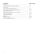
CONTENTS Page Number Introduction .......................................................................................... 3 Important Safeguards & Recommendations ......................................... 4 - 6 Control Panel ........................................................................................ 7 How to use the conventional top oven .................................................. 8 - 9 How to use the multifunction bottom main oven ....................................
Dear Customer, Thank you for purchasing a Kenwood KDBU 170 oven. The safety precautions and recommendations reported below are for your own safety and that of others. They will also provide a means by which to make full use of the features offered by your appliance. Please preserve this booklet carefully. It may be useful in future, either to yourself or to others in the event that doubts should arise relating to its operation.
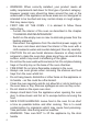
IMPORTANT SAFETY PRECAUTIONS AND RECOMMENDATIONS IMPORTANT: This appliance is designed and manufactured solely for the cooking of domestic (household) food and is not suitable for any non domestic application and therefore should not be used in a commercial environment. The appliance guarantee will be void if the appliance is used within a non domestic environment i.e. a semi commercial, commercial or communal environment. Read the instructions carefully before installing and using the appliance.
• • • • • • • • • • Do not touch the appliance with wet or damp hands (or feet). Do not use the appliance whilst in barefoot.
• • • • • • • • • • • • 6 WARNING: When correctly installed, your product meets all safety requirements laid down for this type of product category. However special care should be taken around the rear or the underneath of the appliance as these areas are not designed or intended to be touched and may contain sharp or rough edges, that may cause injury.
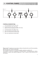
1 - CONTROL PANEL 6 7 Fig. 1.1 1 2 3 4 5 CONTROLS DESCRIPTION 1. Oven temperature knob (Top oven) 2. Function selector knob (Top oven) 3. Digital electronic programmer (Main oven only) 4. Function selector knob (Main oven) 5. Oven temperature knob (Main oven) 6. Main oven temperature indicator light 7. Top oven temperature indicator light Please note: This appliance incorporates a safety cooling fan which you will hear operating whenever the oven or grill is being used.
2 - HOW TO USE THE CONVENTIONAL TOP OVEN Attention: The oven door becomes very hot during operation. Keep children away. WARNING: The door is hot, use the handle. During use the appliance becomes hot. Care should be taken to avoid touching heating elements inside the oven.
TEMPERATURE KNOB (fig. 2.1) To turn on the heating elements of the oven, set first the function selector to the required setting and then the thermostat knob to the desired temperature. To set the temperature, line up the temperature knob indicator with the required temperature. The elements will turn ON or OFF automatically according to the energy need which is determined by the thermostat. The operation of the heating elements is signalled by a light placed on the control panel.
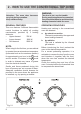
3 - HOW TO USE THE MULTIFUNCTION BOTTOM MAIN OVEN WARNING: The door is hot, use the handle. During use the appliance becomes hot. Care should be taken to avoid touching heating elements inside the oven. GENERAL FEATURES As its name indicates, this is an oven that presents particular features from an operational point of view. In fact, it is possible to insert 7 different programs to satisfy every cooking need.
Fig. 3.1 Fig. 3.2 TEMPERATURE KNOB (fig. 3.2) To turn on the heating elements of the oven, set first the function selector to the required setting and then the thermostat knob to the desired temperature. To set the temperature, line up the temperature knob indicator with the required temperature. The elements will turn ON or OFF automatically according to the energy need which is determined by the thermostat. The operation of the heating elements is signalled by a light placed on the control panel.
GRILLING The infra-red heating element is switched on. The heat is diffused by radiation. Use with the oven door closed and the thermostat knob to to position 225 °C for max 15 minutes, then to position 175 °C. Preheat the oven for about 5 minutes. Introduce the food to be cooked, positioning the rack as close to the grill as possible. The dripping pan should be placed under the rack to catch the cooking juices and fats. Use with the oven door closed.
SLOW HEATING AND KEEPING FOOD WARM The upper element and the circular element connected in series, are switched on; also the fan is on. The heat is diffused by forced convection with the most heat being produced by the upper element. The temperature must be regulated between 50°C and 140°C with the thermostat knob. Recommended for: To keep foods hot after cooking. To slowly heat already cooked foods. CONVECTION COOKING WITH VENTILATION The upper and lower heating elements and the fan turn on.
4 - OVEN TEMPERATURE GUIDE Cooking process Oven heat Gas mark Keeping food hot, milk puddings very cool Electric oven temperature °C °F ½ 120 250 cool 1 140 275 cool 2 150 300 Low temperature roasting, shortbread moderate 3 160 325 Victoria sandwich, plain fruit cake, baked fish moderate 4 180 350 Small cakes, choux pastry fairly hot 5 190 375 Short pastry, Swiss rolls, soufflés fairly hot 6 200 400 High temperature roasting, flaky pastry, scones hot 7 220 425 Puf
5 - DIGITAL ELECTRONIC PROGRAMMER (MAIN OVEN ONLY) CLOCK and TIMER with “ TOUCH CONTROL” KEYS Keys: and MODE Touched simultaneously (for more than 2 seconds): • setting the clock; • setting the timer volume (by touching once, along with the “MODE” key); • to cancel automatic cooking at any time.
“TOUCH-CONTROL” KEYS The “touch-control” keys shall be operated by the fingers (just by touching the key). When using touch controls it is best to use the ball of your finger rather than the tip. The keys are automatically deactivated: • 8 seconds after the last selection; the deactivation is indicated by an acoustic signal (“beep”). To reactivate just touch the “ MODE ” key or the “ for more than 2 seconds.
SETTING THE TIMER VOLUME You can select from three volume levels. • Touch the “ • Touch the “ MODE ” key; you can read on the display the current timer volume (“ton1”, “ton2” or “ton3”). • Touch the “ • Timer volume activated: the last displayed. • After about 8 seconds an acoustic signal (“beep”) will sound confirming the volume setting; then the time of day will be displayed. ” and “ ” keys simultaneously for more than 2 seconds. ” key to listen or change the timer volume.
6 - CLEANING AND MAINTENANCE GENERAL ADVICE Enamelled parts: • All the enamelled parts must be cleaned with a sponge and soapy water or other non-abrasive products. Dry preferably with a microfibre or soft cloth. Acidic substances like lemon juice, tomato sauce, vinegar etc. can damage the enamel if left too long. • • • • • Before you begin cleaning, you must ensure that the appliance is switched off at the oven switch.
WIRE RACKS • Assemble the wire racks to the oven walls using the 2 screws (Fig.6.1a - 6.1b). • Slide into the guides, the shelf and the tray (fig. 6.2a - 6.2b). The shelf must be fitted so that the safety notch, which stops it sliding out, faces the inside of the oven; the guard rail shall be at the back. • To dismantle, operate in reverse order. BOTTOM MAIN OVEN TOP OVEN Fig. 6.1a Guard rail Stop notch Fig. 6.2a Fig. 6.1b Guard rail Stop notch Fig. 6.
Inside of oven: The oven should always be cleaned after use when it has cooled down. The cavity should be cleaned using a mild detergent solution and warm water. Suitable proprietary chemical cleaners may be used only on enamel after first consulting the instructions supplied with the oven cleaner and testing a small sample on the oven cavity. Abrasive cleaning agents or scouring pads/cloths should not be used on the cavity surface.
REMOVING THE OVEN DOORS The oven doors can easily be removed as follows: • Open the door to the full extent (fig. 6.4a). • Open the lever “A” completely on the left and right hinges (fig. 6.4b). • Hold the door as shown in fig. 6.4. • Gently close the door (fig. 6.4c) until left and right hinge levers “A” are hooked to part “B” of the door (fig. 6.4b). • Withdraw the hinge hooks from their location following arrow “C” (fig. 6.4d). • Rest the door on a soft surface.
TOP AND LOWER OVEN DOOR REMOVABLE INNER PANE OF GLASS Cleaning the panes of glass The oven door is fitted with no. 2 panes: • no. 1 outside; • no. 1 inner; To clean the panes on both sides it is necessary to remove the inner pane as follows. Fig. 6.5a Do not use harsh abrasive cleaners or sharp metal scrapers to clean the oven door glass since they scratch the surface, which may result in shattering of the glass. A Removing the inner pane of glass 1. • • • 2.
Replacing the inner pane of glass 1. Make sure the door is locked open (see fig. 6.5c). 2. • Replace the inner pane: Check that the four rubber pads are in place (“D” in Fig. 6.6a). Check that you are holding the pane the correct way. You should be able to read the wording on it as it faces you. Insert the pane in the left “E” and right “F” slide guides (fig. 6.6b), and gently slide it to the retainers H (fig. 6.6c). Top oven door only: Reassemble the seal “G” in the correct way (fig. 6.
Advice for the installer IMPORTANT • • The appliance is designed and approved for domestic use only and should not be installed in a commercial, semi commercial or communal environment. Your product will not be guaranteed if installed in any of the above environments and could affect any third party or public liability insurances you may have. Appliance installation and maintenance must only be carried out by QUALIFIED TECHNICIANS and in compliance with the local safety standards.
7 - INSTALLATION IMPORTANT • The appliance should be installed by a QUALIFIED INSTALLATION TECHNICIAN. The appliance must be installed in compliance with regulations in force. The built under double oven shall be fitted under the working surface into a kitchen base unit (width and depth 60 cm) but you must ensure that it is properly ventilated. Installation requires a compartment as illustrated and described in next chapters: • Installation “A” between Existing Side Cabinets (560 or 600 mm GAP) (figs. 7.
INSTALLATION “A” BETWEEN EXISTING SIDE CABINETS (560 or 600 mm GAP) INSTALLATION “A” 560 mm Gap (figs. 7.1a, 7.1b, 7.2a, 7.2c) • Mount the 2 (two) metal supports “B” (supplied with the appliance in a separate kit) as indicated in Figs. 7.1b or 7.2c. • Fig. 7.2c only - prepare 2 wood uprights “A” (width 20-50 mm, thickness 18 mm, length 650 mm); mount the 2 wood uprights “A” to the cabinet walls as indicated in figure. • Build in the double oven making it slide on the metal supports “B”. Fig. 7.
INSTALLATION “A” INSTALLATION “B” 600 mm Gap Fig. 7.2a Pre existing 600 mm cabinetry Fig. 7.2b 570 (*) Measure calculated from the underneath of the worktop to the top support base of the “B” supports. min WARNING ! VERY IMPORTANT The underside of the cabinet shall be opened to allow correct air circulation. 720 min (*) 650 A 538 718 B 600 18 20 0 -5 A 4 5 20 15 54 59 22 20 B Support base Fig. 7.
INSTALLATION “C” BY USING HOUSING UNIT (figs. 7.3a, 7.3b, 7.3c) • Remove the single oven shelf, if fitted, as indicated in figure 7.3a. • Remove the upper cross member support as indicated in figure 7.3b. • Cut the bottom of the housing as indicated in figure 7.3b. • Screw oven base housing to adjoining cabinetry by suitable screws (not supplied) as indicated in figure 7.3c. • Check the position of the cabinet legs to ensure the cut-out does not interfere with the legs support.
INSTALLATION “C” 720 min (*) (*) Measure calculated from the underneath of the worktop to the top support base of the “B” supports. 600 30 Cabinet for installing the oven B 40 Remove single oven shelf, if fitted. 40 Support base Fig. 7.3a 42 B 30 15 36 15 18 18 Fig. 7.3b 25 30 538 718 B 4 54 59 5 Fig. 7.
FIXING THE DOUBLE OVEN The double oven should then be secured by 6 screws (not supplied) fitted into the holes provided at the sides of the oven (Fig. 7.4). If you open the oven doors, you will see some screw holes. Remember the housing should not be free standing but be secured to the wall and/or adjacent fittings. Adjust the hinges of furniture door adjacent to the double oven to allow a 5 - 7 mm gap between the furniture door and the oven frame.
IMPORTANT: To avoid damage to the lower trim please note the following instructions. The lower trim is designed to allow for good air circulation and the correct opening of the oven door. To ensure the trim is not damaged due to the appliance being placed on the floor, the appliance should be suitably supported as in below illustrations. After installation the appliance door should be slowly opened to ensure no damage has occurred.
8 - ELECTRICAL INSTALLATION IMPORTANT: The appliance must be installed in accordance with the manufacturer’s instructions. Incorrect installation, for which the manufacturer accepts no responsibility, may cause damage to persons, animals and property. The connection of the appliance to earth is mandatory. The manufacturer declines all responsibility for any inconvenience resulting from the inobservance of this condition.
ELECTRICAL FEEDER CABLE CONNECTION WARNING: If the power supply cable is damaged, it must be replaced only by an authorised service agent in order to avoid a hazard. To connect the supply cable: • Unscrew the screws “A” securing the cover plate “B” behind the oven (fig. 8.1). • Remove the cover plate “B”. • Remove the screws “C” from the cable clamp (fig. 8.2). • Insert the mains cable (type H05RR-F or H05VV-F - 3 x 2,5 mm2 section) into the cable protector “P”.
9 - GUARANTEE Your new “KENWOOD” product comes with 12-month guarantee covering all parts and labour. If your appliance proves to be defective as a result of faulty materials or workmanship during the guarantee period, these parts will be repaired or replaced free of charge. AFTER SALES SERVICE Should you require service, spares or product information and advice: • Please Telephone 0843 362 1934.
Descriptions and illustrations in this booklet are given as simply indicative. The manufacturer reserves the right, considering the characteristics of the models described here, at any time and without notice, to make eventual necessary modifications for their construction or for commercial needs.
Code: 1104497 - ß1