
User's Manual


9401941
E
INSTALLATION
5.
INSTALLATION PLANNING
-
CONTROL STATIONS
5-1. Antenna system
e vehicle and determine how and where
Control station. The antenna system seect~on de-
pends on many factors and
IS
beyond the scope of this
cable runs for protection against
pinching or
manual. Your KENWOOD dealer can help you select
g wiring,
and radio installation to prevent,over-
an antenna system that will best serve your particular
needs.
4-2. Antenna 5-2. Radio location
The favored
location
for an antenna Is In the center
Select a convenlent location for your control stat~on
of a large, flat conduct~ve area, usually at the roof
ten-
rad~o which is as close as practical to the antenna cable
ter The trunk Ild
IS
preferred, bond the trunk
and
entry pornt Secondly, use your system's power supply
vehicle
chassis
using ground straps to ensure the Ild 1s
(whlch supplles the voltage and current requ~red for
at chassis ground
your system) Make sure
suff~c~ent air can flow around
the
rad~o and power supply to allow adequate cool~ng
4-3. Radio
The universal mount bracket allows the radio to be
mounted in a variety of ways. Be sure the mounting
surface is adequate to support the radio's weight. Al-
low sufficient space around the radio for air cooling.
Position the radio close enough to the vehicle operator
to permit easy access to the controls when driving.
4-4.
DC
Power and wiring
1
Th~s rad~o may be ~nstalled In negatlve ground eec-
tr~cal systems only Reverse polar~ty
will
cause the
f
cable fuse to blow Check the veh~cle ground polar-
I
~ty before ~nstallat~on to prevent wasted time and
1
effort
k
2
Connect the posltive power lead d~rectly to the ve-
t
i
h~cle battery pos~tive term~nal Connect~ng the Posi-
t
tive lead to any other posltlve voltage source In the
I.
veh~cle
IS
not recommended
F
If
DC
power is to be controlled by the vehicle ign~tion
1
"""""
switch,
a
switching relay should be used to switch the
/
posltwe power lead The vehcle
ignition
switch then
1
controls
DC
to the relay co~l
I
1
3
Connect the ground lead d~rectly to the battery
negatlve termlnal
4
The cable prov~ded wlth the radlo
IS
suff~c~ent to
handle the maximum radio current demand If the
cable must be extended, be sure the
addit~onal wire
IS
suff~c~ent for the current to be carr~ed and length
of the added lead
SERVICE
This radio is designed for easy servicing. Refer to
the schematic diagrams, printed circuit board views,
and alignment procedures contained in this manual.
Note
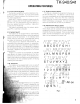
When you modify your radio as described in systern
set-up, take the following precaution.
The rating of pin
7
(SB) of the accessory connector
cable
(KCT-19) on the rear of the radio is 13.6V
(IA).
Insert a 1A fuse if you use the SB pin for external
equipment.
Accessory connector cable
(KCT-19)
Fuse
(IA)
If you do not intend to use the 3.5-mm jack for the
external speaker, fit the supplied speaker-jack cap
(B09-0235-XX) to stop dust and sand getting in.
Speaker-jack cap
(B09-0235-XX)