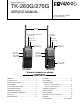
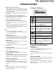
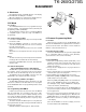
VHF FM TRANSCEIVER TK-260G/270G SERVICE MANUAL © 1999-9 PRINTED IN JAPAN B51-8493-00(S) 1425 Antenna (T90-0679-05):M Knob (CHANNEL SELECTOR) (K29-5341-03) Knob (ENC) (K29-5331-03) Knob (VOL) (K29-5332-03) Knob (VOL) (K29-5332-03) Cabinet assy (A02-2391-23) Knob (PTT) (K29-5334-13) Knob (PTT) (K29-5334-13) Knob (MONI) (K29-5333-13) Knob (MONI) (K29-5333-13) Cabinet assy (A02-2385-23) Key top (DTMF) (K29-5330-02) TK-260G TK-270G M market models are shown. CONTENTS GENERAL ......................
TK-260G/270G GENERAL / SYSTEM SET-UP INTRODUCTION ● SCOPE OF THIS MANUAL This manual is intended for use by experienced technicians familiar with similar types of commercial grade communications equipment. It contains all required service information for the equipment and is current as of the publication date. Changes which may occur after publication are covered by either Service Bulletins or Manual Revisions. These are issued as required.
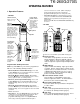
TK-260G/270G OPERATING FEATURES causes an error tone to sound. (When changing a channel from high to low power, all channels programmed with high power are changed to low.) 1. Operation Features • TK-260G Channel selector Rotate to select a channel (1 ~ 8). Antenna LED indicator Lights red while transmitting. Lights green while receiving. Flashes orange while receiving a 2-Tone or DTMF signal that matches the one set up in your transceiver. Flashes red when the battery power is low while transmitting.
TK-260G/270G OPERATING FEATURES u 3 keys , •, 2,3 °These are PF (Programmable Function) keys. Press each key to activate its auxiliary function. i DTMF keypad Used for storing and transmitting DTMF numbers. o SP/MIC jacks Connect an optional speaker/ microphone here. !0 Display (See page 5.) 2. Programmable keys The functions the FPU programs to the function keys are described in the following sections.
TK-260G/270G OPERATING FEATURES 9) Reverse (REV) (Note: C type only) When the REV switch is pressed, transmission can be performed with the receive frequency and receive signaling, and reception can be performed with the transmit frequency and transmit signaling. When REV is on, HORN ALERT and PUBLIC ADDRESS do not work. 3. Display (TK-270G only) 10) Selectable QT (SEL QT) (TK-270G M types only) When the SEL QT switch is pressed, QT frequency can be temporarily changed with the CH switch.
TK-260G/270G OPERATING FEATURES 3) Scan Stop Condition The scan stops temporarily if the following conditions are satisfied. 1 The receiving signal matches the signalling code in your radio that is set by the programming software (KPG-56D). 2 When the Monitor key is depressed. 4) Scan Channel Types 1 Priority channel is the most important channel for scan, and always detects a signal during scan and when the scan stops temporarily. 2 Non-priority channels detect a signal during scan.
TK-260G/270G OPERATING FEATURES 4) Battery Warning This transceiver has a battery warning feature. If low voltage is detected during transmission, the transceiver warns you by a flashing red "LED". When the voltage is detected to be even lower during transmission, the transceiver stops transmission and warns you by a flashing red "LED" and a beep. Please notice "indication" for the battery exchange, charging time by flashing red LED and beep. 5) "TOT" Pre-Alert The transceiver has a "TOT" pre-alert timer.
TK-260G/270G OPERATING FEATURES / REALIGNMENT REALIGNMENT 7. Audible user feedback tones The transceiver outputs various combinations of tones to notify the user of the transceiver operating state. The main tones are listed below The high tone is 1477Hz, the mid tone is 941Hz, and the low tone is 770Hz. • Power on tone This tone is output when the transceiver is turned on. (The high tone is output for 500ms.) 1.
TK-260G/270G REALIGNMENT 4. Checksum Executing this function, "TUNING" appears on the display of TK-270G while calculating the checksum . When the calculation is completed, the display returns to normal and PC displays the checksum of the radio. 5.PC Mode 5-1. Preface The TK-260G/270G transceiver is programmed using a personal computer, a programming interface (KPG-22) and programming software (KPG-56D). The programming software can be used with an IBM PC or compatible.
TK-260G/270G REALIGNMENT 9. If you want to continue programming other TK-260G/ 270Gs, repeat steps 5 to 8. Notes: ● To start the Firmware Programmer from KPG-56D, the Fpro path must be set up by the KPG-56D Setup. ● This mode cannot be entered if the Firmware Programming mode is set to Disable in the Programming software (KPG56D). ● When programming the firmware, it is recommend to copy the data from the floppy disk to your hard disk before you update the radio firmware.
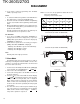
TK-260G/270G REALIGNMENT 8. Self Programming Mode (TK-270G only) Write mode for frequency data and signalling etc. Mainly used by the person maintaining the user equipment. X57-587X Compoent Side 8.1 Self programming mode setting Remove D17 from the TX-RX unit (Figure 3) (K models only). Hold down the [LAMP]+[●] switches and turn the power switch on. When the self programming mode is entered, [SELF] appears on the display.
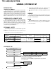
TK-260G/270G REALIGNMENT No. Function Choices Display Remarks 3 TX frequency Step 2.5kHz-1MHz STP_250 Same as RX frequency. STP_1000 Blank ———— 100.0000T.100.0000 550.0000MHz 4 TX Signaling Same as RX signaling. 5 Option Signaling OFF NONE____ Default DTMF DTMF____ 2-TONE 2TONE___ 6 ID 000___ID___ Display when an item is selected 9999999999 (about 0.5 seconds) 12345678 Display of the current setting (If it is 8 or more digits, scroll it.) ——987 Display when a code is input (Input it with DTMF key.
TK-260G/270G REALIGNMENT 8-3. Function Setting Mode No. Function Choices This is a mode for using the panel keys to make function settings without using the FPU, that operate on all channels. Pressing the [LAMP] when "SELF" is displayed, sets the Function Setting Mode. Select an item set using [3] then change the selection with the encoder. The data displayed using [2] is stored in the memory and then proceeds to the next item. Pressing [3] proceeds to the next item without storing it in the memory.
TK-260G/270G REALIGNMENT No.
TK-260G/270G REALIGNMENT ° No. Function Choices Display 34 D Key D Code DKA_D_CD Remarks Default When the [ ] switch is pressed while "SELF" is displayed, the memory is reset. Assignment 1-16/1s 35 DTMF Code SQ Default When the memory is reset, mode data and model data are not reset. DKA_16__ DTMF_OFF Signaling SEL CALL DTMF_SEL 36 Inter Mediaate 0-9,A-D,*,# IMC__#_ Default: # (Can be set only when Code DTMF signaling = SEL CALL.
TK-260G/270G DISASSEMBLY FOR REPAIR Separating the case assembly from the chassis. 1. Remove the two knobs z and three round units x. 2. Remove the two screws c. 3. Expand the right and left sides of the bottom of the case assembly, lift the chassis, and remove it from the case assembly v. TK-260G Separating the chassis from the unit. • TK-260G 1. Remove the twelve small screws m, and the three large screws ,. 2.
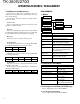
TK-260G/270G CIRCUIT DESCRIPTION 3) IF Amplifier circuit 1. Frequency configuration The receiver utilizes double conversion. The first IF is 49.95 MHz and the second IF is 450 kHz. The first local oscillator signal is supplied form the PLL circuit. The PLL circuit in the transmitter generates the necessary frequencies. Fig. 1 shows the frequencies. CF 450kHz TX/RX : 150~174MHz MCF IF SYSTEM RF AMP 49.95MHz AF AMP 50.4MHz X3 multiply SP TCXO 16.8MHz MIC AMP MIC RX : 199.95~223.
TK-260G/270G CIRCUIT DESCRIPTION 5) Audio amplifier circuit (3) DTMF (High-speed data) The DTMF input signal from the IF IC(IC4) is amplified by IC16(2/2) and goes to IC18, the DTMF decoder. The decoded information is then processed by the CPU. During transmission and standby, the DTMF IC is set to the power down mode when the PD terminal is High. When the line is busy, the PD terminal becomes Low, the power down mode is canceled and decoding is carried out.
TK-260G/270G CIRCUIT DESCRIPTION 3) UNLOCK DETECTOR ANT If a pulse signal appears at the LD pin of IC2, an unlock condition occurs, and the DC voltage obtained form D1, R1, and C6 causes the voltage applied to the microprocessor to go low. When the microprocessor detects this condition, the transmitter is disabled, ignoring the push-to-talk switch input signal.(See Fig.
TK-260G/270G CIRCUIT DESCRIPTION 3) Low battery warning 6. Control Circuit The control circuit consists of a microprocessor (IC13) and its peripheral circuits. It controls the TX-RX unit and transfers data to and from the display unit. IC13 mainly performs the following: (1) Switching between transmission and reception by the PTT signal input. (2) Reading system, group, frequency, and program data from the memory circuit. (3) Sending frequency program data to the PLL.
TK-260G/270G CIRCUIT DESCRIPTION/SEMICONDUCTOR DATA 8. CONTROL SYSTEM Keys and channel selector circuit. The signal from the keys and channel selector are directly input to the microprocessor, as shown in fig. 10. 5M Pin No. Name 60 VSS 61 OSC 62 CE 63 CL 64 DI Channel selector PTT 3 KEYAD PTT SW 47k 87 IC13 -COM 25 EN1 47k LAMP SW 100k MONI SW 16 EN2 KOUT0 KOUT1 KOUT2 KOUT3 KIN0 KIN1 KIN2 KIN4 KIN3 27 EN3 TK-260G I/O Active Function I/O Oscillation terminal Chip enable.
TK-260G/270G SEMICONDUCTOR DATA Microprocesser : 30622M4102GP (TX-RX UNIT : IC13) ■ Pin function Pin No.
TK-260G/270G DESCRIPTION OF COMPONENTS DISPLAY UNIT (X54-3250-10) (TK-270G Only) Ref. No. Use/Function IC501 Q501 Q502 D505 D506 D507 D508~510 D511 D512~516 IC Transistor Transistor Diode LED Diode LED LED LED Operation/Condition LCD driver Current driver / LCD back light LED AVR DC switch Speed up LCD back light Voltage reference LED /Key pad back light LCD back light LED /Key pad back light TX-RX UNIT (X57-587X-XX) Ref. No.
TK-260G/270G PARTS LIST L: Scandinavia K: USA Y: PX (Far East, Hawaii) T: England Y: AAFES (Europe) X: Australia * New Parts. ! indicates safety critical components. Parts without Parts No. are not supplied. Les articles non mentionnes dans le Parts No. ne sont pas fournis. Teile ohne Parts No. werden nicht geliefert. P: Canada E: Europe M: Other Areas TK-260G/270G New Ref. No. Address parts Parts No. Description Ref. No.
TK-260G/270G PARTS LIST TX-RX UNIT (X57-5870-10) New Ref. No. Address parts Parts No. Description D507 MA2S111 DIODE IC501 LC75823W IC(MOS-IC) Q501 Q502 2SB1132(Q,R) 2SC4617(S) TRANSISTOR TRANSISTOR Destination TX-RX UNIT (X57-5870-XX) -10:TK-260G K,M -11:TK-270G K -21:TK-270G M D18 B30-2019-05 LED(RED/GRN) C1 C3,4 C5 C6 C8 CK73GB1H471K CC73GCH1H070B CC73GCH1H100C CK73GB1C104K CC73GCH1H030B CHIP C CHIP C CHIP C CHIP C CHIP C 470PF 7.0PF 10PF 0.10UF 3.
TK-260G/270G PARTS LIST TX-RX UNIT (X57-5870-XX) New Ref. No. Address parts Parts No. Description Destination New Ref. No. Address parts Parts No. Description C173 C174 C176 C177 C178 C92-0567-05 CK73GB1H102K CC73GCH1H101J CK73GB1C473K C92-0560-05 CHIP-TAN CHIP C CHIP C CHIP C CHIP-TAN 68UF 1000PF 100PF 0.047UF 10UF 6.3WV K J K 6.3WV C247 C248 C249 C250 C251 CK73GB1E123K CK73GB1H103K CK73GB1H222K CK73GB1C683K CK73GB1C104K CHIP C CHIP C CHIP C CHIP C CHIP C 0.012UF 0.010UF 2200PF 0.068UF 0.
TK-260G/270G PARTS LIST TX-RX UNIT (X57-5870-XX) New Ref. No. Address parts Parts No. Description Destination New Ref. No. Address parts Parts No. Description L14 L15 L17 L18 -20 L21 * * L40-1085-92 L40-5675-92 L34-4550-05 L92-0138-05 L40-1875-92 SMALL FIXED INDUCTOR(100NH) SMALL FIXED INDUCTOR(56NH) AIR-CORE COIL FERRITE CHIP SMALL FIXED INDUCTOR(18NH) R22 R23 R26 R27 R28 ,29 RK73GB1J472J RK73GB1J122J RK73GB1J561J RK73GB1J270J RK73GB1J271J CHIP R CHIP R CHIP R CHIP R CHIP R 4.7K 1.
TK-260G/270G PARTS LIST TX-RX UNIT (X57-5870-XX) New Ref. No. Address parts Parts No. Description Destination New Ref. No. Address parts Parts No. Description R92 R93 R94 R95 R96 RK73GB1J100J RK73GB1J332J RK73GB1J681J RK73GB1J222J RK73GB1J151J CHIP R CHIP R CHIP R CHIP R CHIP R 10 3.3K 680 2.2K 150 J J J J J 1/16W 1/16W 1/16W 1/16W 1/16W R157 R158 R159 R160 R161 RK73GB1J102J R92-1252-05 RK73GB1J102J RK73GB1J222J RK73GB1J563J CHIP R CHIP R CHIP R CHIP R CHIP R 1.0K 0 OHM 1.0K 2.
TK-260G/270G PARTS LIST TX-RX UNIT (X57-5870-XX) New Ref. No. Address parts Parts No. Description R232 R233 R234 R235 R237 RK73GB1J152J R92-1252-05 RK73GB1J124J RK73GB1J334J R92-1252-05 CHIP R CHIP R CHIP R CHIP R CHIP R 1.
TK-260G/270G EXPLODED VIEW (TK-260G) B A 53 51 C 31 E 701 2 49 10 D 1 29 22 24 50 37 30 52 SP 16 44 I L 18 IC1 2 Lx8 Gx2 19 B 40 39 13 TX-RX unit (A/2) B 28 26 3 A 11 J 3 J 702 17 TX-RX unit (B/2) 25 12 F K 703 A B C D E F G J K L M2.6x4 M2x3.5 NUT NUT NUT M2.6x6 M3x4 φ2x4.
TK-260G/270G EXPLODED VIEW (TK-270G) D C C 51 48 31 D 49 701 1 23 1 27 22 SP 50 37 16 52 43 47 J H DISPLAY unit 705 42 H M2 4 18 I 6 2.5 20 M3 4 14 5 21 J32-0925-04 IC1 2 46 Lx8 B 19 15 38 39 13 B TX-RX unit (A/2) 28 26 3 A 11 J J 702 3 17 TX-RX unit (B/2) 25 12 F K 703 704 A B C D F H I J K L M2.6x4 M2x3.5 NUT NUT M2.6x6 M2x3 M2x5 φ2x4.
TK-260G/270G PACKING F E 32.PACKING FIXTURE (H12-1487-02) 33.PROTECTION BAG (H25-0085-04) 1 7. WARRANTY CARD (B46-0470-00) : K 45.BELT HOOK (J29-0624-03) 34.PROTECTION BAG (H25-2012-04) 2 ANT. HELICAL ANTENNA (T90-0679-05) : M 8. INSTRUCTION MANUAL (B62-1113-00) : 270G 9. INSTRUCTION MANUAL (B62-1129-00) : 260G 4. CAP (SP/MIC) (B09-0351-03) 41.SP/MIC HOLDER (J21-4493-04) M. SCREW SET (N99-2012-05) 32.PACKING FIXTURE (H12-1487-02) 35.ITEM CARTON CASE (H52-1413-02) : 270G 36.
TK-260G/270G ADJUSTMENT Test Equipment Required for Alignment 1. Test Equipment Standard Signal Generator (SSG) 2. Power Meter 3. 4. 9. Deviation Meter Digital Volt Meter (DVM) Oscilloscope High Sensitivity Frequency Counter Ammeter AF Volt Meter (AF VTVM) Audio Generator (AG) 10. Distortion Meter 11. 12. Spectrum Analyzer Tracking Generator 13. 14. 8Ω Dummy Load Regulated Power Supply 5. 6. 7. 8.
TK-260G/270G ADJUSTMENT Repair Jig (Extention Flat cable : part No. E37-0851-05) This cable is used for connecting the TK-270G display unit and TX/RX unit when you test or repair the transceiver. ■ Frequency and signalling The set has been adjusted for the frequencies shown in the following table. When required. re-adjust them following the adjustment procedure to obtain the frequencies you want in actual operation. Frequency (MHz) Display unit Extention Flat cable TX/RX unit Channel No.
TK-260G/270G ADJUSTMENT ° Press [ ], to enter tuning mode. Use the [2 ] key to write tuning data through the tuning modes, and the channel selector knob to adjust the tuning requirements (1 to 256 appears on LCD). Use the [3] key to select the adjustment item through the tuning modes. Use the [●] key to adjust 3 or 5 point tuning, and use the [LAMP] key to switch between Wide/Narrow. Panel Tuning Mode K,M TEST Ch L L’ M H’ H LCD display (Tuning mode) Wide/Narrow indicator H.P.O.W. . Adjustment item 1.
TK-260G/270G ADJUSTMENT Since the TK-260G cannot be tuned from the panel, the FPU (KPG-56D) should be used for adjustment. Adjust the receive BPF waveform according to the appropriate adjustment item. Common Section Item 1. Setting 2. VCO lock voltage RX TX Condition Measurement Test equipment Terminal 1) BATT terminal voltage:7.5V 2) SSG Standard modulation [Wide] MOD:1kHz, DEV:3kHz [Narrow] MOD:1kHz, DEV:1.
TK-260G/270G ADJUSTMENT Item Condition 7. Max DEV Adjust [Wide] Measurement Test equipment Terminal Power meter ANT Dev meter SP/MIC connector Oscilloscope AG AF VTVM 1) Adj item [MAX] Adjust [∗∗∗] AG:1kHz / 150mV Dev meter filter LPF:15kHz HPF:OFF 2) Adj item [.M A X] ➞ [.M.A.X] ➞ [.M.A.X. .] Adjust [∗∗∗] PTT:ON [Narrow] 1) Adj item [MAX .] Adjust [∗∗∗] PTT:ON 8. MIC [Panel Test Mode] Sensitivity 1) CH-Sig:1-1 Check AG:1kHz / 15mV LPF:15kHz PTT:ON 9.
TK-260G/270G ADJUSTMENT Item 14.DQT Devition Adjust [Wide] [Narrow] 15.DTMF Deviation Adjust [Wide] [Narrow] 16.TONE Deviation Adjust [Wide] [Narrow] 17.BATT Detection Writing 18.BATT Detection Check 38 Condition Measurement Test equipment Terminal 1) Adj item [FDQT] Power meter Adjust [∗∗∗] Dev meter LPF:3kHz Oscilloscope HPF:OFF 2) Adj item [F.D Q T] ➞ [F.D.Q.T] ➞ [F.D.Q.T. .] Adjust [∗∗∗] PTT:ON 3) Adj item [FDQT.
TK-260G/270G ADJUSTMENT Item Condition Measurement Test equipment Terminal DVM 1. Sensitivity Adj item [SENS] Adjustment Adjust [∗∗∗] fL fc fH [S E N S] ➞ [S E N S] ➞ [S E N S ] PTT : ON 2. BPF (PANEL TEST MODE) Tracking generator CH-Sig 2-1 spectrum analyzer Tra-G setting -40dBm CH-Sig 1-1 CH-Sig 3-1 . ... Adjustment Specifications/ Remark Parts Method Encoder knob fL : ([S E N S]) : [88] fC : (S E N S) : [134] . ... . . . .. fL . . . . .
TK-260G/270G ADJUSTMENT Adjustment points TX-RX unit (X57-587) Component side view Foil Side View MIC ANT LV SP BPF VR1 L307 C13 CN3 Battery terminal TC1 IC12 L305 L306 ANT MIC IC14 BPF CV MIC VR1 : Frequency adjustment SP TC1 : Transmit lock voltage adjustment TC2 : Receive lock voltage adjustment L305: L306: Band-pass filter waveform adjustment L307: BPF : Band-pass filter test point CV(LV) : Lock voltage adjustment terminal. } Fig.
A B C D E F G H I J K L M N O P Q R S TK-260G/270G PC BOARD VIEW 1 2 DISPLAY UNIT (X54-3250-10) Foil Side View DISPLAY UNIT (X54-3250-10) Component Side View DISPLAY UNIT (X54-3250-10) Component Side View 16 1 17 64 L502 R518 R511 R516 C513 R515 R514 R513 IC501 E 49 33 48 L501 C506 D502 D504 C509 C508 CP501 C501 R501 32 D505 Q501 R517 R522 D501 B C515 C516 D507 C Q502 LCD D506 C507 R508 D503 R509 R507 CP502 R510 D515 D516 Ref. NO.
A B C D E TK-260G/270G 1 2 F G H I J K L M N O P Q R S PC BOARD VIEW 1 5 16 R104 16 8 9 1 4 IC5 IC10 IC6 8 8 1 C165 L40 CP6 CP8 CP7 CP9 CP11 CP12 CP13 CP14 CP4 R120 R121 IC13 L41 C162 26 R100 25 1 Address 8E 6F 4O 4P 4N 5D 5O 7O 4L 6M 7K 3I 6J 8J 6G 6E 8K 4E 8N 5D 5D 5E 3L 6M 5F 7M 7M 4F 3M C180 CP20 R203 R126 R140 R256 C185 50 CP2 C193 R250 R249 CP3 51 75 76 C189 R155 100 R146 D17 1 CP5 C192 D19 CN1 C270 C138 C141 X3 LV C100 9 D23 16
A B C D E F G H I J K L M N O P PC BOARD VIEW Q R S TK-260G/270G 2 VR2 C68 L26 C55 EN1 C23 C24 D3 C57 L10 D8 C54 R28 R29 C35 6 L5 L7 C28 C301 R318 1 C89 L30 7 C3 C82 R42 8 IC301 4 5 C5 C25 C303 C88 Q10 Q25 R113 C144 L17 R58 R301 C305 C62 C72 R111 Q24 R112 C143 R110 C307 L302 C311 D303 R308 R313 D7 R57 Q9 L9 C262 C75 C41 C11 R26 R5 L307 C4 R6 C53 5 C52 L6 C12 L19 R10 Q6 R305 C13 C40 C27 R18 B C C324 C310 L306 E R27 Q2 R39
A B C D E TK-260G/270G 1 2 F G H I J K L M N O P Q 1 A6 A5 9 TAI 8 9 16 R104 IC5 IC6 8 S MUTE M MUTE 5 16 TAO 1 4 1 I G L38 IC9 1 D21 L41 C162 R119 CP4 C157 26 R100 25 R126 IC7 C156 Ref. NO. IC1 IC2 IC3 IC4 IC5 IC6 IC7 IC8 IC9 IC10 IC11 IC12 IC13 IC14 IC15 IC16 IC17 IC18 IC19 IC301 Q1 Q2 Q3 Q4 Q6 Q7 Q8 Q9 Q10 Q11 Q12 Q13 Q14 Q15 Q16 Q17 Q18 Q19 Q20 Q21 Q22 Q23 Ref. NO.
A B C D E F G H I J K L M N O P Q R SCHEMATIC DIAGRAM S TK-260G 1 2 3 4 5 6 7 • Note) Component marked with a dot ( ) are Parts of pattern 1.
T TK-270G U V W X Y Z AA AB AC AD AE AF AG AH AI AJ AK AL SCHEMATIC DIAGRAM 1 2 3 4 5 6 7 • Note) Component marked with a dot ( ) are Parts of pattern 1.
TK-260G/270G TK-260G/270G BLOCK DIAGRAM 57 58
59 5 RXLO D5 D10 +5.6dBm MIC 10.5mVrms TX C239 RX 3 13 Q6 ALC 15 C12 18 IC14 6 IC15 SW 19 AF (1kHz) 275mVrms C206 Power Module +17.0dBm AF (1kHz) Q301 9 8 265mVrms 5.0W AF VR 7 10 XF1 6 C243 3 C173 + IC17 5 C246 D6 SP C14 120mVrms DAC Q30 0.63mVrms IC4 FM IF SYSTEM C242 + 180mVrms IF2 (450kHz) 6 IC16 7 460mVrms AF (1kHz) Q3 C28 7 IC301 2 –7.9dBm C303 Q4 –3.2dBm RF (162.05MHz) C30 AG is set to the MIC input becomes 3kHz DEV. at 1kHz MOD.
TK-260G/270G OPTIONS KMC-17 (Speaker microphone) KMC-17 Parts List Ref. No. KMC-21 (Speaker microphone) New parts Description Parts No.
TK-260G/270G SPECIFICATION General Frequency Range ............................................................ 150~174MHz Number of channels ......................................................... Max. 8 (TK-260G) Max. 128 (TK-270G) Number of groups ............................................................ Max. 128 (TK-270G) Channel Spacing .............................................................. 25kHz, 30kHz (Wide) 12.5kHz, 15kHz (Narrow) PLL Step ...............................................