INSTRUCTION MANUAL VHF APCO P25 TRANSCEIVER TK-5210 © B62-1796-00 (K) 09 08 07 06 05 04 03 02 01 00
THANK YOU We are grateful you chose KENWOOD for your land mobile radio applications. We believe this easy-to-use transceiver will provide dependable communications to keep personnel operating at peak efficiency. KENWOOD transceivers incorporate the latest in advanced technology. As a result, we feel strongly that you will be pleased with the quality and features of this product.
One or more of the following statements may be applicable: FCC WARNING This equipment generates or uses radio frequency energy. Changes or modifications to this equipment may cause harmful interference unless the modifications are expressly approved in the instruction manual. The user could lose the authority to operate this equipment if an unauthorized change or modification is made.
The RBRC Recycle seal found on KENWOOD nickel-cadmium (Ni-Cd) battery packs indicates KENWOOD’s voluntary participation in an industry program to collect and recycle Ni-Cd batteries after their operating life has expired. The RBRC program is an alternative to disposing Ni-Cd batteries with your regular refuse or in municipal waste streams, which is illegal in some areas. For information on Ni-Cd battery recycling in your area, call (toll free) 1-800-8-BATTERY (1-800-822-8837).
PRECAUTIONS • • • • • • • • • • • Do not charge the transceiver and battery pack when they are wet. Ensure that there are no metallic items located between the transceiver and the battery pack. Do not use options not specified by KENWOOD. If the die-cast chassis or other transceiver part is damaged, do not touch the damaged parts. If a headset or headphone is connected to the transceiver, reduce the transceiver volume. Pay attention to the volume level when turning the squelch off.
Turn the transceiver power off in the following locations: • In explosive atmospheres (inflammable gas, dust particles, metallic powders, grain powders, etc.). • While taking on fuel or while parked at gasoline service stations. • Near explosives or blasting sites. • In aircrafts. • In medical institutions or near persons using pacemakers. • • • • • • Do not disassemble or modify the transceiver for any reason. Do not place the transceiver on or near airbag equipment while the vehicle is running.
CONTENTS UNPACKING AND CHECKING EQUIPMENT .......................... 1 SUPPLIED ACCESSORIES ................................................ 1 PREPARATION .......................................................... 2 BATTERY PACK PRECAUTIONS ........................................... 2 INSTALLING/ REMOVING THE (OPTIONAL) BATTERY PACK ................... 7 INSTALLING THE (OPTIONAL) ANTENNA ................................... 8 INSTALLING THE BELT CLIP ..............................................
(CONTENTS CONTINUED…) DTMF (DUAL TONE MULTI FREQUENCY) CALLS ................. MAKING A DTMF CALL (K3 MODELS ONLY) .......................... AUTODIAL (K2 AND K3 MODELS ONLY) ............................... STUN CODE ......................................................... EMERGENCY CALLS ................................................. SCRAMBLER (FM)/ ENCRYPTION (APCO) ......................... SECURE (ENCRYPTED) TRANSMISSION .................................. SELECTING THE SCRAMBLER CODE ...............
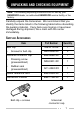
UNPACKING AND CHECKING EQUIPMENT Note: The following unpacking instructions are for use by your KENWOOD dealer, an authorized KENWOOD service facility, or the factory. Carefully unpack the transceiver. We recommend that you identify the items listed in the following table before discarding the packing material. If any items are missing or have been damaged during shipment, file a claim with the carrier immediately.
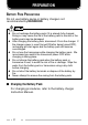
PREPARATION BATTERY PACK PRECAUTIONS Do not use battery packs or battery chargers not recommended by KENWOOD. ◆ Do not recharge the battery pack if it is already fully charged. Doing so may cause the life of the battery pack to shorten or the battery pack may be damaged. ◆ After charging the battery pack, disconnect it from the charger. If the charger power is reset (turned ON after being turned OFF), recharging will start again and the battery pack will become overcharged.
Information concerning the (optional) Li-ion battery pack: The battery pack includes flammable objects such as organic solvent. Mishandling may cause the battery to rupture producing flames or extreme heat, deteriorate, or cause other forms of damage to the battery. Please observe the following prohibitive matters. DANGER • • • • • Do not disassemble or reconstruct battery! The battery pack has a safety function and protection circuit to avoid danger.
• • • • • • • Do not charge the battery near fires or under direct sunlight! If the battery’s protection circuit is damaged, the battery may charge at extreme current (or voltage) and an abnormal chemical reaction may occur. The battery may generate heat or smoke, rupture, or burst into flame.
• • • • • • Do not reverse-charge or reverse-connect the battery! The battery pack has positive and negative poles. If the battery pack does not smoothly connect with a charger or operating equipment, do not force it; check the polarity of the battery. If the battery pack is reverse-connected to the charger, it will be reverse-charged and an abnormal chemical reaction may occur. The battery may generate heat or smoke, rupture, or burst into flame.
■ Using the Li-ion Battery Pack • • • Charge the battery pack before using it. To keep the battery discharge at a minimum, remove the battery pack from the equipment when it is not in use. Store the battery pack in a cool and dry location. When storing the battery pack for a long period: 1 Remove the battery pack from the equipment. 2 Discharge the battery pack, if possible. 3 Store the battery pack in a cool (below 25°C/ 77°F) and dry location.
INSTALLING/ REMOVING THE (OPTIONAL) BATTERY PACK 1 2 3 Match the guides of the battery pack with the corresponding grooves on the upper rear of the transceiver, then firmly press the battery pack to lock it in place. Lock the safety catch to prevent accidentally pressing the release latch and removing the battery pack. To remove the battery pack, lift the safety catch, press the release latch, then pull the battery pack away from the transceiver.
INSTALLING THE (OPTIONAL) ANTENNA Screw the antenna into the connector on the top of the transceiver by holding the antenna at its base and turning it clockwise until secure. Optional antenna INSTALLING THE BELT CLIP If necessary, attach the belt clip using the two supplied 3 x 8 mm binding screws. Belt clip Note: If the belt clip is not installed, its mounting location may get hot during continuous transmission or when left sitting in a hot environment.
INSTALLING THE CAP OVER THE UNIVERSAL CONNECTOR 1 2 If you are not using an optional speaker/ microphone or headset, install the cap over the universal connector. Secure the cap in place using the attached screw. Universal connector cap INSTALLING THE (OPTIONAL) SPEAKER/ MICROPHONE OR HEADSET 1 2 Insert the guide of the speaker/ microphone or headset connector into the groove of the universal connector. Secure the connector in place using the attached screw.
C GETTING ACQUAINTED A B Microphone Speaker MIC 6 There are 3 models available: K model: Basic model. K2 model: Equipped with a display and 4-key keypad (A, B, ). K3 model: Equipped with a display and full keypad. The above illustration displays the K3 model.
q Power switch/ Volume control Turn clockwise to switch the transceiver ON. Rotate to adjust the volume. Turn counterclockwise fully to switch the transceiver OFF. w Selector knob Rotate this control to activate its programmable function {page 15}. The default setting is Channel Select. e Concentric switch Rotate this switch to activate one of its programmable functions {page 15}. r Transmit/ Receive/ Battery low indicator Lights red while transmitting.
!1 Side 2 key Press to activate its programmable function {page 15}. Acts as an Up key for certain transceiver settings. !2 Side 3 key Press to activate its programmable function {page 15}. Acts as a Down key for certain transceiver settings. !3 Display (K2 and K3 models only) Refer to the display on page 13. !4 A key (K2 and K3 models only) Press to activate its programmable function {page 15}. The programmed name appears on the bottom of the display.
DISPLAY (K2 AND K3 MODELS ONLY) Indicator Description Appears when you are using Scan mode. Appears when the current channel is added to the scanning sequence. Appears when the current channel is programmed as a Priority channel. “P1” represents Priority channel 1. “P2” represents Priority channel 2. “PP” represents Priority channels 1 and 2. Appears when low transmit power is selected. “HI” appears when using high transmit power. Appears when the key lock function is activated.
Indicator Description Appears when the Tactical Group function is activated. Appears when the monitor function is activated and when the squelch off function is activated. Appears when the scrambler/ encryption function is activated. Displays the operating zone number. Displays the operating zone and channel number or channel name. Also displays various text messages depending on the function being used. Displays the functions of the A, B, keys.
PROGRAMMABLE FUNCTIONS Refer to the following tables to determine which functions are available for appropriate channels.
Programmable Function Conventional FM Conventional APCO Reference Page 43 Light 1 ✓ ✓ Low Transmit Power ✓ ✓ 43 Monitor ✓ ✓ 44 Monitor Momentary ✓ ✓ 44 None ✓ ✓ 44 ✓ • 35, 44 44 Operator Selectable Tone 1 ✓ • OST Up 1 ✓ • 45 Scan ✓ ✓ 23, 45 ✓ ✓ 23, 45 ✓ ✓ 24, 45 Scrambler/ Encryption ✓ ✓ 33, 45 Scrambler/ Encryption Code 1 ✓ ✓ 33, 45 ✓ • 26, 46 ✓ • 26, 46 ✓ ✓ 46 Squelch Level 1 ✓ • 46 Squelch Off ✓ • 46 Squelch Off Momentary ✓ • 46 Stat
Programmable Function Conventional FM Conventional APCO Reference Page Zone Down ✓ ✓ Zone Select 5 ✓ ✓ 48 Zone Up ✓ ✓ 48 1 2 3 4 5 6 48 Autodial, Clock, Display Character, Individual, Key Delete, Light, Operator Selectable Tone, OST Down, OST Up, Scan Program, Scrambler/ Encryption Code, Selcall, Selcall Status, Squelch Level, Status, and Talkgroup are available only on K2 and K3 model transceivers. Channel Select can be programmed only on the Selector knob.
BASIC OPERATIONS SWITCHING POWER ON/ OFF Turn the Power switch/ Volume control clockwise to switch the transceiver ON. Turn the Power switch/ Volume control counterclockwise to switch the transceiver OFF. ■ Transceiver Password K2 and K3 model transceivers may be password protected. If the transciever is protected, “INPUT PASSWORD” will appear on the display when the power is turned ON. To unlock the transceiver, enter the correct password: 1 Enter a character using the Side 2 and Side 3 keys.
ADJUSTING THE VOLUME Rotate the Power switch/ Volume control to adjust the volume. Clockwise increases the volume and counterclockwise decreases it. SELECTING A ZONE AND CHANNEL Select the desired zone using the selector knob or the keys programmed as Zone Up/ Zone Down. Each zone contains a group of channels Select the desired channel using the selector knob or the keys programmed as Channel Up/ Channel Down. Each channel is programmed with settings for transmitting and receiving.
TRANSMITTING 1 Select the desired zone and channel using the selector knob and the Zone Up/ Zone Down or Channel Up/ Channel Down keys. 2 Press the key programmed as Monitor or Squelch Off to check whether or not the channel is free. 3 Press the PTT switch and speak into the microphone. Release the PTT switch to receive. • • • If the channel is busy, wait until it becomes free. The LED indicator lights red while transmitting and green while receiving a signal.
■ Making Group Calls (APCO) Channels programmed for APCO operation already have a Group ID assigned. For these channels, you do not need to perform steps 1 to 3, below. Otherwise, on K2 and K3 model transceivers, if a key has been programmed with Talkgroup, you can select a group ID from the list to make a call to those parties. 1 Press the key programmed as Talkgroup.
RECEIVING 1 2 Select the desired zone and channel using the selector knob and the Zone Up/ Zone Down or Channel Up/ Channel Down keys. (If the Scan function has been programmed, you can switch it on or off as desired.) When you hear a caller’s voice, readjust the volume as necessary. • If signaling has been programmed on the selected channel, you will hear a call only if the signal tone matches the tone set up on your transceiver. Note: Signaling allows your transceiver to code your calls.
SCAN Scan is useful for monitoring signals on the transceiver channels. While scanning, the transceiver checks for a signal on each channel and only stops on a channel if a signal is present. To begin scanning, press the key programmed as Scan. • • • On K2 and K3 model transceivers, the icon appears on the display. The channels included in the scan list are scanned. When a signal is detected on a channel, Scan pauses on that channel.
PRIORITY SCAN A Priority channel must be programmed in order for Priority Scan to function. When using a single Priority channel, the transceiver will automatically change to the Priority channel when a call is received on it, even if a call is being received on a normal channel. When using dual Priority channels, Priority channel 1 is given precedence over Priority channel 2.
SCAN PROGRAMMING (K2 AND K3 MODELS ONLY) Using the key programmed with Scan Program, you are able to reprogram your scan list. 1 Press the key programmed as Scan Program. • 2 • • 3 The icon appears on the display and blinks. Press the Side 2 and Side 3 keys to select the zone or channel you will add to or remove from the scan list. The icon appears on the display for zones/ channels that are added to the scan list. Press the A key to toggle between Zone Select and Channel Select.
FleetSync: ALPHANUMERIC 2-WAY PAGING FUNCTION FleetSync is an Alphanumeric 2-way Paging Function, and is a protocol owned by KENWOOD Corporation. FleetSync enables a variety of paging functions on your transceiver, some of which depend on dealer programming. Note: This function is available only in Conventional FM Operation. SELCALL (SELECTIVE CALLING) A Selcall is a voice call to a particular station or to a group of stations.
■ Identification Codes An ID code is a combination of a 3-digit Fleet number and a 4-digit ID number. Each transceiver must have its own Fleet and ID number. • • • • • Enter a Fleet number (100 ~ 349) to make a group call. Enter an ID number (1000 ~ 4999) to make an individual call in your fleet. Enter a Fleet number to make a call to all units in the selected fleet (Fleet call). Enter an ID number to make a call to the selected ID in all fleets (Supervisor call).
■ Transmitting 1 2 Select your desired zone and channel. Press the key programmed as Status to enter Status mode or Selcall Status to enter Selcall mode. • 3 In Selcall mode, press the Side 2 and Side 3 keys to select the ID of the station you want to call. • 4 5 If Manual Dialing is enabled, you can enter the station ID by using the DTMF keypad. Press the A key to enter Status Mode. Press the Side 2 and Side 3 keys to select the status ID you want to transmit.
■ Reviewing Messages in the Stack Memory 1 Press and hold the key programmed as Selcall, Status, or Selcall Status for 1 second to enter Stack mode. • 2 3 The last received message is displayed with the message number. Press the Side 2 and Side 3 keys to select the desired message. Press the Side 1 key to return to normal operation. • • To delete the selected message, press the B or # key. To confirm the deletion, press the B or # key again.
DTMF (DUAL TONE MULTI FREQUENCY) CALLS Note: DTMF calls can be made only in Conventional FM Operation. MAKING A DTMF CALL (K3 MODELS ONLY) ■ Manual Dialing 1 2 Press and hold the PTT switch. Enter the desired digits using the DTMF keypad. • • The corresponding DTMF tones sound each time you press a key. If you release the PTT switch, transmit mode will end even if the complete number has not been sent. ■ Store & Send 1 Enter the desired digits using the DTMF keypad.
AUTODIAL (K2 AND K3 MODELS ONLY) Autodial allows you to quickly call DTMF numbers that have been programmed onto your transceiver. 1 Press the key programmed as Autodial. • 2 • 3 The first entry in the Autodial list appears on the display. Press the Side 2 and Side 3 keys or enter the appropriate DTMF number (01 ~ 32) to select your desired Autodial list number. The stored entry appears on the display. Press the PTT switch to make the call.
EMERGENCY CALLS If your transceiver has been programmed with the Emergency function, you can make emergency calls. Note: Only the Auxiliary (orange) key and the PF1 (orange) key of the optional speaker/ microphone can be programmed with the Emergency function. 1 Press and hold the key programmed as Emergency. • Depending on the delay time programmed into your transceiver, the length of time you must hold the Emergency key will vary.
SCRAMBLER (FM)/ ENCRYPTION (APCO) Note: ◆ The Scrambler function can be used only in Conventional FM Operation. Additionally, the Voice Scrambler board must be installed before this function can be activated. ◆ Ask your dealer for details concerning the Voice Scrambler board and the Encryption DES/AES settings. SECURE (ENCRYPTED) TRANSMISSION Press the key programmed as Scrambler/ Encryption to switch the transceiver to secure (encrypted) transmission.
SELECTING THE ENCRYPTION KEY 1 2 Press the key programmed as Scrambler/ Encryption Code (K2 and K3 Models Only) or press and hold the key programmed as Scrambler/ Encryption for 1 second, to enter Key Selection Mode. Select the new Encryption key using the Side 2 and Side 3 keys or the keys. • • 3 There are 16 available Encryption keys (1 ~ 16). Each group member must select a key that is in each member’s key list in order for the transceivers to descramble the received signals.
SIGNALING Note: Signaling can be used only in Conventional FM Operation. QUIET TALK (QT)/ DIGITAL QUIET TALK (DQT) Your dealer may have programmed QT or DQT signaling on your transceiver channels. A QT tone/ DQT code is a sub-audible tone/code which allows you to ignore (not hear) calls from other parties who are using the same channel. When a channel is set up with a QT tone or DQT code, squelch will only open when a call containing a matching tone or code is received.
After selecting and setting up your desired tone or code, press the Operator Selectable Tone key to activate the OST function. Press this key again to turn the OST function OFF. OPTIONAL SIGNALING Your dealer may also program several types of option signaling for your transceiver channels. ■ 2-tone Signaling 2-tone Signaling opens the squelch only when your transceiver receives a call containing matching 2 tones.
VOICE OPERATED TRANSMISSION (VOX) VOX can be activated or deactivated by your dealer. VOX operation allows you to transmit hands-free. This feature can only be used if you are using a supported headset. When operating VOX, you must set a VOX Gain level. This setting allows the transceiver to recognize sound levels. If the microphone is too sensitive, it will begin transmitting when there is noise in the background. If it is not sensitive enough, it will not pick up your voice when you begin speaking.
VOX OPERATION 1 Connect the headset to the transceiver. • 2 The VOX function does not activate when a headset is not connected to the accessory terminal of the transceiver. Press and hold the key programmed as VOX for 2 seconds. • 3 On K2 and K3 model transceivers, the the display. To transmit, simply speak into the microphone. • 4 The transceiver recognizes sound levels depending on the VOX Gain level.
CLOCK (K2 and K3 Models Only) If activated by your dealer, your transceiver can track the time with its built-in clock. The time will display momentarily when the transceiver power is turned ON. Additionally, you can view the clock any time by pressing the key programmed as Clock. Note: Removing or leaving the battery pack uncharged for extended periods will cause the clock time to clear.
ADVANCED OPERATIONS Your transceiver operations vary according to the functions that your dealer has programmed onto the transceiver keys. Following is brief overview of the programmable functions. Refer to those functions which have been programmed onto your transceiver. • • • • • Autodial (AD) Press this key to quickly call a DTMF number that has been pre-stored in your transceiver memory.
• • • • • • Channel Select Using the selector, turn clockwise to increase the channel number and counterclockwise to decrease the channel number. If a channel has not been programmed, an error tone will sound. Channel Up (CH▲) Press this key to increase the channel number. Press and hold this key to cycle up through the channel numbers. When the highest channel number is reached, the transceiver will “roll-over” to the lowest channel number and continue cycling up.
• • • • • External Speaker (ESP) Press this key to switch the speaker from the transceiver’s built-in speaker to an optional external speaker. When pressed, all messages and tones will sound from the optional external speaker that is attached to the transceiver, rather than from the transceiver’s built-in speaker. Function (FNC) Press this key to activate the second function of the programmable keys. “FC” appears on the display when this key is pressed.
• • • Key Lock (LCK) Press and hold this key for 1 second to lock the transceiver keys. When activated, the front panel keypad and the programmable function keys (other than those listed below) can no longer be used and “LOCKED” appears on the display. The following programmable functions can still be operated: Emergency, Light, Monitor, Monitor Momentary, Squelch Off, Squelch Off Momentary, Function, and Key Lock. Likewise, the Selector, Concentric switch, and Toggle switch still function normally.
Channels programmed with low power cannot be switched to high power, but channels programmed with high power can be switched to low power and then back to high power by pressing this key again. When using high power, the icon appears on the display. • • • • • Monitor (MON) Press this key to turn the transceiver signaling off. This will allow you to listen to all calls that are received on your icon selected channel. While monitor is activated, the appears on the display.
• • • • • • OST Up (OS▲) Press this key to increase the Operator Selectable Tone number of your selected channel. (This key functions similar to the Operator Selectable Tone key.) Scan (SCN) Press this key to scan your transceiver channels for a icon appears on the signal. While scanning, the display. Press this key again to quit scan. Refer to “SCAN” on page 23 for details. Scan Delete (DEL) Press this key during scan operation to temporarily delete a channel from the scanning sequence.
• • • • • • Selcall (SEL) Press this key to enter Selcall mode. Press and hold this key to enter Stack mode. Refer to “FleetSync: ALPHANUMERIC 2-WAY PAGING SYSTEM” on page 26 for details. Selcall Status (SES) Press this key to enter Selcall mode. Press and hold this key to enter Stack mode. Refer to “FleetSync: ALPHANUMERIC 2-WAY PAGING SYSTEM” on page 26 for details. Speaker Attenuation Press this key (on the optional speaker/microphone) to attenuate the received voice signals.
• • • • • • Status (STS) Press this key to enter Status mode. Press and hold this key to enter Stack mode. Refer to “FleetSync: ALPHANUMERIC 2-WAY PAGING SYSTEM” on page 26 for details. Tactical Group (TAC) Press and hold this key for 1 second to register the selected channel as a Tactical Group channel. Press and hold this key for 3 seconds to register all channels within the current zone as Tactical Group channels. Talk Around (TA) Press this key to toggle Talk Around ON and OFF.
• • • Press and hold the VOX key for 2 seconds to turn VOX Operation mode ON or OFF. Refer to “VOICE OPERATED TRANSMISSION (VOX)” on page 37 for details. Zone Down (ZN▼) Press this key to decrease the zone number. Press and hold this key to cycle down through the zone numbers. When the lowest zone number is reached, the transceiver will “roll-over” to the highest zone number and continue cycling down. After selecting your desired zone, the channel display will reappear.
BACKGROUND OPERATIONS Your dealer can activate a variety of transceiver functions to perform without any additional operation on your part. TIME-OUT TIMER (TOT) The Time-out Timer is used to prevent any caller from using a channel for an extended period of time. If you continuously transmit for a period of time that exceeds the programmed time, the transceiver will stop transmitting and an alert tone will sound. To stop the tone, release the PTT switch.
LOW BATTERY WARNING Low Battery Warning alerts you when the battery needs to be recharged. On all transceivers, your dealer can set an alert tone to sound and the LED indicator to blink red when the battery power is low. On K2 and K3 model transceivers, the battery power icon displays the battery power remaining, as illustrated below. High Sufficient Low Very low When the battery power is very low, recharge or replace the battery pack.
PTT ID PTT ID is the transceiver unique ID code which sent each time the PTT switch is pressed. Note: PTT ID can be made only in FM Operation. If Beginning of Transmit is set, the ID signal is transmitted when you press the PTT switch. If End of Transmit is set, the ID signal is transmitted when you release the PTT switch. If both are set, the ID signal is transmitted when you press and release the PTT switch.