TK-2170/ TK-3170/ TK-3173 VHF FM TRANSCEIVER/ UHF FM TRANSCEIVER/ UHF FM TRANSCEIVER INSTRUCTION MANUAL ÉMETTEUR-RÉCEPTEUR FM VHF/ ÉMETTEUR-RÉCEPTEUR FM UHF/ ÉMETTEUR-RÉCEPTEUR FM UHF MODE D’EMPLOI TRANSCEPTOR DE FM VHF/ TRANSCEPTOR DE FM UHF/ TRANSCEPTOR DE FM UHF MANUAL DE INSTRUCCIONES © B62-1809-10 (K) 09 08 07 06 05 04 03 02 01
TK-2170/ TK-3170/ TK-3173 INSTRUCTION MANUAL ENGLISH VHF FM TRANSCEIVER/ UHF FM TRANSCEIVER/ UHF FM TRANSCEIVER
THANK YOU We are grateful you have chosen KENWOOD for your land mobile radio applications. We believe this easy-to-use transceiver will provide dependable communications to keep personnel operating at peak efficiency. KENWOOD transceivers incorporate the latest in advanced technology. As a result, we feel strongly that you will be pleased with the quality and features of this product.
One or more of the following statements may be applicable: FCC WARNING This equipment generates or uses radio frequency energy. Changes or modifications to this equipment may cause harmful interference unless the modifications are expressly approved in the instruction manual. The user could lose the authority to operate this equipment if an unauthorized change or modification is made.
Attention (U.S.A. Only): The RBRC Recycle seal found on KENWOOD nickel-cadmium (Ni-Cd) battery packs indicates KENWOOD’s voluntary participation in an industry program to collect and recycle Ni-Cd batteries after their operating life has expired. The RBRC program is an alternative to disposing Ni-Cd batteries with your regular refuse or in municipal waste streams, which is illegal in some areas. For information on Ni-Cd battery recycling in your area, call (toll free) 1-800-8-BATTERY (1-800-822-8837).
PRECAUTIONS • • • • • • • • • • • Do not charge the transceiver and battery pack when they are wet. Ensure that there are no metallic items located between the transceiver and the battery pack. Do not use options not specified by KENWOOD. If the die-cast chassis or other transceiver part is damaged, do not touch the damaged parts. If a headset or headphone is connected to the transceiver, reduce the transceiver volume. Pay attention to the volume level when turning the squelch off.
Turn the transceiver power off in the following locations: • In explosive atmospheres (inflammable gas, dust particles, metallic powders, grain powders, etc.). • While taking on fuel or while parked at gasoline service stations. • Near explosives or blasting sites. • In aircrafts. • In medical institutions or near persons using pacemakers. • • • • • • • • Do not disassemble or modify the transceiver for any reason. Do not place the transceiver on or near airbag equipment while the vehicle is running.
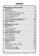
CONTENTS UNPACKING AND CHECKING EQUIPMENT ............................. 1 SUPPLIED ACCESSORIES ....................................................... 1 PREPARATION .............................................................. 2 BATTERY PACK PRECAUTIONS .................................................. 2 INSTALLING/ REMOVING THE (OPTIONAL) BATTERY PACK ......................... 7 INSTALLING/ REMOVING ALKALINE BATTERIES .................................... 8 INSTALLING THE (OPTIONAL) ANTENNA ..............
SCAN ....................................................................... ADD TO SCAN/ DELETE FROM SCAN .......................................... PRIORITY SCAN ............................................................. GROUP SCAN (TK-3173 ONLY) ............................................ SCAN REVERT .............................................................. FleetSync: ALPHANUMERIC 2-WAY PAGING FUNCTION ................... SELCALL (SELECTIVE CALLING) ..............................................
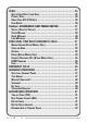
UNPACKING AND CHECKING EQUIPMENT Note: The following unpacking instructions are for use by your KENWOOD dealer, an authorized KENWOOD service facility, or the factory. Carefully unpack the transceiver. We recommend that you identify the items listed in the following table before discarding the packing material. If any items are missing or have been damaged during shipment, file a claim with the carrier immediately.
PREPARATION BATTERY PACK PRECAUTIONS Do not use battery packs or battery chargers not recommended by KENWOOD. ◆ Do not recharge the battery pack if it is already fully charged. Doing so may cause the life of the battery pack to shorten or the battery pack may be damaged. ◆ After recharging the battery pack, disconnect it from the charger. If the charger power is reset (turned ON after being turned OFF), recharging will start again and the battery pack will become overcharged.
Information concerning the (optional) Li-ion battery pack: The battery pack includes flammable objects such as organic solvent. Mishandling may cause the battery to rupture producing flames or extreme heat, deteriorate, or cause other forms of damage to the battery. Please observe the following prohibitive matters. DANGER • • • • • • Do not disassemble or reconstruct battery! The battery pack has a safety function and protection circuit to avoid danger.
• • • • • • • Use only the specified charger and observe charging requirements! If the battery is charged in unspecified conditions (under high temperature over the regulated value, excessive high voltage or current over regulated value, or with a remodelled charger), it may overcharge or an abnormal chemical reaction may occur. The battery may generate heat or smoke, rupture, or burst into flame.
• Do not touch a ruptured and leaking battery! If the electrolyte liquid from the battery gets into your eyes, wash your eyes out with fresh water as soon as possible, without rubbing your eyes. Go to the hospital immediately. If left untreated, it may cause eye-problems. • Do not charge the battery for longer than the specified time! If the battery pack has not finished charging even after the regulated time has passed, stop it. The battery may generate heat or smoke, rupture, or burst into flame.
■ USING THE LI-ION BATTERY PACK • • • Charge the battery pack before using it. To keep the battery discharge at a minimum, remove the battery pack from the equipment when it is not in use. Store the battery pack in a cool and dry location. When storing the battery pack for a long period: 1 Remove the battery pack from the equipment. 2 Discharge the battery pack, if possible. 3 Store the battery pack in a cool (below 25°C/ 77°F) and dry location.
INSTALLING/ REMOVING THE (OPTIONAL) BATTERY PACK 1 Align the battery pack with the back of the transceiver, then press the battery pack and transceiver firmly together until the release latch clicks, locking it in place. 2 Lock the safety catch into place to prevent accidentally pressing the release latch and removing the battery.
INSTALLING/ REMOVING ALKALINE BATTERIES ◆ Do not install batteries in a hazardous environment where sparks could cause an explosion. ◆ Never discard batteries in fire; extremely high temperatures can cause batteries to explode. ◆ Do not short circuit the battery case terminals. ◆ Do not use rechargeable batteries. Note: ◆ If you do not plan to use the transceiver for a long period, remove the batteries from the battery case.
INSTALLING THE (OPTIONAL) ANTENNA Screw the antenna into the connector on the top of the transceiver by holding the antenna at its base and turning it clockwise until secure. Note: The antenna is neither a handle, a key ring retainer, nor a speaker/ microphone attachment point. Using the antenna in these ways may damage the antenna and degrade your transceiver’s performance.
INSTALLING THE CAP OVER THE SPEAKER/ MICROPHONE JACKS Install the cap over the speaker/ microphone jacks when not using an optional speaker/ microphone. 1 Place the cap over the jacks so that the locking tabs insert into the transceiver grooves. 2 While holding the cap in place, push it towards the bottom of the transceiver until the tabs on the cap click into place. Note: To keep the transceiver water resistant, you must cover the speaker/ microphone jacks with the supplied cap.
GETTING ACQUAINTED q w e r t y Microphone u !1 i !3 o !0 Speaker !2 * The transceiver is also available without the DTMF keypad (!2). q Antenna connector Connect an (optional) antenna here {page 9}. w Selector Rotate to activate its programmable function {page 15}. e Power switch/ Volume control Turn clockwise to switch ON the transceiver. Rotate to adjust the volume. Turn counterclockwise fully to switch OFF the transceiver.
r LED indicator Lights red while transmitting. Lights green while receiving a call. Flashes orange while receiving an encoded (2-tone, DTMF signaling, etc.) call. If programmed by your dealer, flashes red when the battery power is low while transmitting. t Safety Catch Lock this catch to avoid accidentally pressing the release latch and removing the battery pack {page 7}. y Release Latch Press the release latch to unlock and remove the battery pack {page 7}.
DISPLAY Indicator Description This icon is not used on this transceiver. Appears when QT, DQT, DTMF, or 2-tone signaling is deactivated (by pressing the Monitor key) or when Squelch is open (by pressing the Squelch Off key). In Conventional zones, appears when using 2-tone or DTMF signaling. In Trunking zones (TK-3173 only), appears when receiving dispatch calls with a Fix ID or Group ID (if enabled by your dealer).
Indicator Description Appears when using low transmit power. Appears when the scrambler function is activated. Displays the battery status. The battery icon with all 3 strength bars represents full power while an empty battery icon represents very low power. Appears when the selected zone is added to the scanning sequence. Appears when the VOX function has been activated. Appears when the AUX function has been activated. Appears when the OST function has been activated.
PROGRAMMABLE FUNCTIONS The Auxiliary, Side 1, Side 2, S, A, keys {pages 11 and 12} can be programmed with the functions below. Please contact your dealer for further details on these functions. Note: ◆ The selector can be programmed as either CH/GID Up/Down or Zone Up/Down. ◆ Your dealer can also enable the selector to be used when making setting adjustments (as an optional method for using the keys).
OPERATING BASICS OVERVIEW Your dealer can program your transceiver with Conventional zones. (TK-3173 transceivers can be programmed with Trunking zones and Conventional Zones.) The transceiver can handle up to 128 zones with up to 128 channels/ 250 group IDs. Zones, channels/ group IDs, and their functions are programmed by your dealer. SWITCHING POWER ON/ OFF Turn the Power switch/ Volume control clockwise to switch the transceiver ON. • • A beep sounds and the display momentarily lights up.
To enter the password using the DTMF keypad (keypad models only): 1 Press the DTMF keys corresponding to the password. • 2 Press the A or # key to delete an incorrect character. Press and hold the A or # key to delete all entered characters. Press the S or • key to confirm the password. If you enter an incorrect password, an error tone sounds and the transceiver remains locked. ADJUSTING THE VOLUME Rotate the Power switch/ Volume control to adjust the volume.
TRUNKING ZONES (TK-3173 ONLY) PLACING A DISPATCH CALL 1 2 Press and hold the PTT switch. If the “Proceed” tone sounds, communication is possible; speak into the microphone to make your call. Release the PTT switch to receive. • • For best sound quality at the receiving station, hold the microphone approximately 1.5 inches (3 ~ 4 cm) from your mouth. Your dealer can deactivate the Proceed tone, if necessary. Ask your dealer for details.
PLACING A TELEPHONE CALL 1 Press the key programmed as Autodial. • 2 Press the keys or rotate the selector to select your desired Autodial list number. • 3 4 The stored entry appears on the display. Press and hold the Side 1 key to toggle the display between the list number and the entry name. Press the PTT switch to make the call or the Side 2 key to transmit the DTMF number. When the called party responds, press the PTT switch and speak into the microphone.
CONVENTIONAL ZONES TRANSMITTING 1 2 Select the desired zone and channel using the selector and the Zone or CH/GID keys. Press the key programmed as Monitor or Squelch Off to check whether or not the channel is free. • 3 If the channel is busy, wait until it becomes free. Press the PTT switch and speak into the microphone. Release the PTT switch to receive. • For best sound quality at the receiving station, hold the microphone approximately 1.5 inches (3 ~ 4 cm) from your mouth.
2-TONE SIGNALING 2-tone Signaling is enabled or disabled by your dealer. This function opens the squelch only when the transceiver receives the 2 tones programmed in your transceiver. Transceivers that do not transmit the correct tones will not be heard. ■ TRANSMITTING 1 2 3 4 Select your desired zone and channel. Press the key programmed as 2-tone.
OPERATOR SELECTABLE TONE (OST) You can change the preset encode and decode tones for the selected channel. Your dealer can program up to 40 tones on your transceiver. To turn OST ON or OFF, press the key programmed as OST. • The OST indicator ( this function is activated. ) appears on the display when To change the preset encode/decode tones: 1 Press and hold the key programmed as OST for approximately 1 second. • 2 3 The OST name appears on the display.
2 Press the key programmed as VOX. 3 Press the keys or rotate the selector to increase or decrease the VOX Gain level. • • 4 The VOX Gain can be adjusted from levels 1 to 10. While adjusting the gain level, speak into the headset microphone as you would while under normal operation, to test the sensitivity level. • • 5 The current VOX Gain level appears. When the microphone recognizes a sound, the LED lights orange.
SCAN If the Scan function is programmed, zones or channels can be scanned by pressing the key programmed as Scan. Scan can be used as either Single Scan, Multi Scan, or List Scan (TK-3173 only). • • • Single Scan monitors only the channels of the currently selected zone, which have been added to the scanning sequence. If set up to scan the Priority channel, the Priority channel will be scanned even if it is not within the currently selected zone.
ADD TO SCAN/ DELETE FROM SCAN Press the key programmed as Scan Delete/Add, to add or remove each channel/ group ID to or from the scan sequence. • The channel/ group ID add indicator ( ) will appear on the display when the selected channel/ group ID is added to the scan sequence. Press and hold the key programmed as Scan Delete/Add, to add or remove each zone to or from the scan sequence. • The zone add indicator ( ) will appear on the display when the selected zone is added to the scan sequence.
SCAN REVERT The Revert zone and channel/ group ID is the zone and channel/ group ID which the transceiver automatically selects when pressing the PTT switch during Scan, to transmit. Your dealer can program 1 of 6 types of Scan Reverts for your transceiver: • • • • • • Last Called: The last zone and channel/ group ID received is assigned as the new revert zone and channel/ group ID. Last Used: The last zone and channel/ group ID responded to is assigned as the new revert zone and channel/ group ID.
FleetSync: ALPHANUMERIC 2-WAY PAGING FUNCTION FleetSync is an Alphanumeric 2-way Paging Function, and is a protocol owned by KENWOOD Corporation. FleetSync enables a variety of paging functions on your transceiver, some of which depend on dealer programming. SELCALL (SELECTIVE CALLING) A Selcall is a voice call to a particular station or to a group of stations. ■ TRANSMITTING 1 2 3 Select your desired zone and channel/ group ID.
■ IDENTIFICATION CODES An ID code is a combination of a 3-digit Fleet number and a 4-digit ID number. Each transceiver must have its own Fleet and ID number. • • • • • Enter a Fleet number (100 ~ 349) to make a group call. Enter an ID number (1000 ~ 4999) to make an individual call in your fleet. Enter a Fleet number make a call to all units in the selected fleet (Fleet call). Enter an ID number to make a call to the selected ID in all fleets (Supervisor call).
3 In Selcall Mode, press the keys, rotate the selector, or enter an appropriate number using the DTMF keypad to select the ID of the station you want to call. • 4 5 Press the S key to enter Status Mode. Press the keys, rotate the selector, or enter an appropriate number using the DTMF keypad to select the status ID you want to transmit. • 6 Alternatively, press and hold the S or key to enter Manual Dialing mode.
■ REVIEWING MESSAGES IN THE STACK MEMORY 1 Press and hold the key programmed as Selcall, Status, or Selcall + Status for 1 second to enter Stack Mode. • 2 Press the keys or rotate the selector to select the desired message. • 3 The last received call ID/ stack number appears on the display. Press and hold the S key to toggle between the call ID/ status message and the channel name. Press the S key to return to normal operation. • • To delete the selected message, press the A or # key.
DTMF (DUAL TONE MULTI FREQUENCY) CALLS MANUAL DIALING (KEYPAD MODELS ONLY) ■ METHOD 1 Press and hold the PTT switch, then enter the desired digits using the front panel keypad. • If your dealer has activated the Keypad Auto PTT function, you need not press the PTT switch while pressing the keys on the keypad in Conventional systems. The DTMF code will be sent automatically when you press a key. ■ METHOD 2 Enter the desired digits using the front panel keypad (maximum of 16 digits).
STORE AND SEND Store and send allows you to make DTMF calls without the need for a DTMF keypad. 1 Press the key programmed as Autodial. • 2 • 3 “ ” appears on the display. Rotate the selector to select a digit. Alternatively, you can enter the digits by using the DTMF keypad (keypad models only). Press the C> key to accept the entered digit and move to the next digit. • Press the A key to delete an incorrect character. Press and hold the A key to delete all entered characters.
3 4 Press the S or key to confirm the list number. Enter the desired name for the list entry using the DTMF keypad. • • 5 Press the S key to confirm the entry. • 6 • If enabled by your dealer, you can also rotate the selector to select a digit. Press the C> key to confirm the digit. Repeat this operation until the complete number is entered. Press the A or # key to delete an incorrect character. Press and hold the A or # key to delete all entered characters. Press the S key to confirm the entry.
2 Press the keys, rotate the selector, or enter an appropriate number using the DTMF keypad (01 ~ 16) to select your desired Autodial list number. • 3 The stored entry appears on the display. Press and hold the Side 1 key to toggle the display between the list number and the entry name. Press the PTT switch to make the call or the Side 2 key to page the selected recipient. ■ CLEARING STORED DTMF NUMBERS 1 Press the key programmed as Autodial Programming.
CONNECT/ DISCONNECT IDS (KEYPAD MODELS ONLY) 1 Press the # key or the key programmed as Autodial. 2 Connect ID: Press the key two times. Disconnect ID: Press the key followed by the # key. Press the PTT switch to make the call or the Side 2 key to page the selected recipient. • 3 The first entry in the Autodial list appears on the display. DTMF SIGNALING DTMF Signaling is either enabled or disabled by your dealer.
EMERGENCY CALLS If your transceiver has been programmed with the Emergency function, you can make emergency calls. Note: Only the Auxiliary (orange) key can be programmed with the Emergency function. 1 Press and hold the key programmed as Emergency. • Depending on the delay time programmed into your transceiver, the length of time you must hold the Emergency key will vary.
ADVANCED OPERATIONS SELECTING A TRANSMIT POWER Each channel is programmed with either high or low transmit power by your dealer. You can change the transmit power of only channels programmed with high transmit power. When you can reliably communicate with other parties without using high transmit power, select low transmit power by pressing the key programmed as Low Transmit Power. Each time you press Low Transmit Power, the transmit power toggles between high and low.
MONITOR/ SQUELCH OFF You can use the key programmed as Monitor/ Squelch Off to listen to weak signals that you cannot hear during normal operation and to adjust the volume when no signals are present on your selected channel. • The icon appears on the display while Monitor/ Squelch Off is activated. Your dealer can program a key with one of 4 functions: • Monitor: Momentarily press to deactivate QT, DQT, DTMF, 2-tone, or Fleetsync Signaling. Press the key again to return to normal operation.
SCRAMBLER Although the scrambler function does not offer complete privacy with your calls, it does prevent others from easily listening in on your calls. When activated, the transceiver distorts your voice so that anybody listening to your conversation will not be able to clearly hear what you are saying. In order for members of your own group to clearly hear your call while you are using the scrambler, all other members must also activate the scrambler functions on their transceivers.
TRANSCEIVER BACKLIGHT To turn the transceiver display backlight on, press the key programmed as Lamp. • Pressing any key other than the PTT switch and the Power switch/ Volume control while the backlight is on will reset the lamp timer, allowing the backlight to remain lit for an additional 5 seconds. To turn the display backlight off immediately, press the Lamp key while the backlight is on.
BACKGROUND OPERATIONS TIME-OUT TIMER (TOT) The purpose of the Time-out Timer is to prevent any caller from using a channel for an extended period of time. If you continuously transmit for a period of time that exceeds the programmed time set by your dealer (default is 1 minute for Conventional and dispatch (Trunking) operation, and 3 minutes for telephone (Trunking) operation), the transceiver will stop transmitting and an alert tone will sound. To stop the tone, release the PTT switch.
BATTERY STATUS INDICATOR The battery status indicator displays the battery power remaining when using an optional battery pack, as illustrated below. (The battery status indicator does not appear while using alkaline batteries.) High Sufficient Low Very Low When the battery power is very low, replace or recharge the battery pack. If activated by your dealer, an alert tone will sound every 30 seconds and the LED indicator will blink red when the battery power is low.