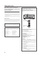
AUDIO VIDEO SURROUND RECEIVER VR-9060 INSTRUCTION MANUAL KENWOOD CORPORATION About the supplied remote control Compared to standard remote controls, the remote control supplied with this receiver has several operation modes. These modes enable the remote control to control other audio/video components. In order to effectively use the remote control it is important to read the operating instructions and obtain a proper understanding of the remote control and how to switch its operation modes (etc.).
Before applying the power Units are designed for operation as follows. U.S.A. and Canada ........................................... AC 120 V only Australia ........................................................... AC 240 V only Europe ............................................................... AC 230 V only Other countries ............ AC 110-120 / 220-240 V switchable Caution : Read this page carefully to ensure safe operation.
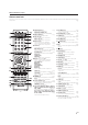
Before applying the power Contents Caution : Read the pages marked safe operation. carefully to ensure Before applying the power ...................................................... 2 Safety precautions ..................................................................... 2 How to use this manual ............................................................ 2 Unpacking .................................................................................. 4 Preparing the remote control ......................
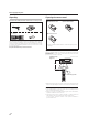
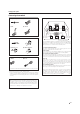
Before applying the power Unpacking Preparing the remote control Unpack the unit carefully and make sure that all accessories are present. FM indoor antenna (1) Remote control unit (1) RC-R0829 AM loop antenna (1) Batteries (R03/AAA) (2) If any accessories are missing, or if the unit is damaged or fails to operate, notify your dealer immediately. If the unit was shipped to you directly, notify your shipper immediately.
Before applying the power Special features True home theater sound § This receiver incorporates a wide variety of surround modes to bring you maximum enjoyment from your video software and audio source.
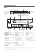
Names and functions of parts Main unit Speaker indicators Listen mode indicators SLEEP indicator MUTE CLIP Input mode indicator indicator indicators *Input channel indicators SP MUTE A B CLIP AUTO DETECT DIGITAL 6CH INPUT L C SW R Input channel indicators light LFE up according to the incoming audio signals. SL S SB SR "S" indicator will light up when the surround component of the audio signals is *Input channel indicators only 1 channel.
Names and functions of parts Remote control unit This remote control unit can be used not only for Kenwood products but also for other non-Kenwood products by setting the appropriate manufacturer’s setup codes. › RECEIVER ON STANDBY INPUT MODE DISC SEL. INPUT SEL. SOURCE DISC SKIP TV LAST TV INPUT TV MUTE TV VOL. INFO TONE BASS BOOST LOUDNESS AUDIO SUBTITLE MUTE ANGLE MENU /SOUND VOLUME TOP MENU /SETUP MULTI ENTER MULTI RETURN /EXIT ON SCREEN /GUIDE DIMMER BAND AUTO/MONO P.
Setting up the system Make connections as shown in the following pages. When connecting the related system components, be sure to refer to the instruction manuals supplied with the components you are connecting. Do not connect the power cord to a wall outlet until all connections are completed. Notes 1. Be sure to insert all connection cords securely. If their connections are imperfect, sound may not be produced or there will be noise inference. 2.
Setting up the system Connecting the terminals 1 Strip coating. 2 Loosen. Speaker placement Center Speaker 3 Insert. 4 Secure. Front Speakers (L, R) Surround Speakers (L, R) *Surround Back Left Speaker 1 Strip coating. Subwoofer Listening position *Surround Back Right Speaker 2 Push the lever. *Surround Back Speaker *For Surround Back speaker, you may place either two Surround Back speakers (Surround Back Left Speaker and Surround Back Right Speaker) for 7.
Setting up the system Connecting a DVD player (6-channel input) If you have connected a DVD player to the receiver with digital connection, be sure to read the “Input mode settings” section carefully.
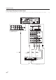
Setting up the system Connecting audio components To AC wall outlet L • The earth terminal with the H symbol is used for noise reduction of record player. It is not for safety earth. R IN PHONO IN CD/DVD REC OUT PLAY IN MD/TAPE OUT Cassette Deck or MD Recorder IN OUT DVD Player or CD Player Moving coil (MC) cartridge record player cannot be used directly from the receiver unit. It can only be used when another equalizer amplifier is connected.
Setting up the system Connecting video components S VIDEO Jacks About the S VIDEO Jacks S VIDEO OUT S VIDEO OUT VIDEO S VIDEO IN VIDEO S VIDEO IN VIDEO S VIDEO IN VIDEO S VIDEO IN VIDEO (DVD) Use the S VIDEO Jacks to make connections to video components with S VIDEO IN/OUT Jacks. (MONITOR) • If you use the S VIDEO jacks to connect your video playback components, be sure to use the S VIDEO jacks when connecting your monitor and video recording components.
Setting up the system Digital connections The digital in jacks can accept DTS, Dolby Digital, or PCM signals. Connect components capable of outputting DTS, Dolby Digital, or standard PCM (CD) format digital signals. If you have connected any digital components to the receiver, be sure to read the “Input mode settings” section carefully.
Setting up the system Connecting video components (COMPONENT VIDEO) If you have connected the receiver to a video component with COMPONENT jacks, you can get a better picture quality than by connecting to the S-VIDEO jacks. * DVD IN input jack is used for either CD/DVD input or DVD/ 6CH input.
Setting up the system Connecting the speakers Surround Back Speaker/s When connecting a single Surround Back Speaker, connect it to SURROUND BACK L terminals and select “SB LARGEx1” or “SB NORMALx1” at Speaker settings.
Setting up the system Connecting to the AV AUX jacks Connecting the antennas The AV AUX jacks are convenient for connection of video components such as a camcorder or a video game. The broadcast reception cannot be made unless the antennas are connected. Connect the antennas correctly as instructed below. AM Loop Antenna AV AUX/GAME Place the supplied loop antenna as far as possible from the receiver, TV set, speaker cords and power cord, and adjust the direction for best reception.
Preparing for surround sound 4 Select a speaker system. Speaker settings To enable you to obtain optimum enjoyment from the receiver’s listening modes, make sure to complete the speaker settings (Subwoofer, Front, Center, Surround and Surround Back Speakers) as described below. 1 Select the SP SETUP and press the SETUP key again so that the subwoofer setting indication “SUBW ON” appears.
Preparing for surround sound 8 Use the MULTI CONTROL knob or MULTI %/fi keys to select the appropriate Surround Speaker setting. If you selected “FRNT LARGE” as the Front Speaker setting, 1 SURR NORMAL : Average size Surround Speakers are connected to the receiver. 2 SURR LARGE : Large size Surround Speakers are connected to the receiver. 3 SURR OFF : Surround Speaker setting mode to the receiver is OFF.
Preparing for surround sound 7 Input the distance to the speakers. 9 Select the display mode. • Indicators appear only for the channels of the speakers selected in step 4. 1 Press the 5/∞ keys or MULTI @/# keys to select the DISP MODE and press the SETUP key. 1 Press the 5/∞ keys or MULTI @/# keys to select the SP DISTANCE on setup displays and press the SETUP key again. 2 Use the MULTI CONTROL knob or MULTI %/fi keys to select the display mode.
Normal playback Listening to a source component Preparing for playback Some preparatory steps are needed before starting playback. VOLUME CONTROL (POWER ON/STANDBY) SPEAKERS INPUT MODE AV AUX/GAME INPUT SELECTOR Turning on the receiver VOLUME%/fi 1 Turn on the power to the related components. 2 Turn on the power to this receiver by pressing the ON/STANDBY) key.
Normal playback Input level adjustment (analog sources only) Adjusting the sound ACTIVE EQ LOUDNESS TONE MULTI CONTROL MULTI CONTROL INPUT SELECTOR SOUND PHONES TONE BASS BOOST SOUND MULTI %/ fi, @/# MULTI %/ fi Input Selector keys VOLUME CONTROL BASS BOOST MUTE LOUDNESS VOLUME%/fi RCV MODE RCV MODE ACTIVE EQ Adjusting the TONE Input level adjustment (analog sources only) If the input level of an analog source signal is too high, the CLIP indicator will light up to indicate the source signa
Normal playback Recording One-touch low frequency emphasis (BASS BOOST) Recording audio (analog sources) You can adjust the sound quality when the receiver is in the PCM stereo and analog stereo modes. Press the BASS BOOST key. • Press the key once to select the maximum (+10) low frequency emphasis setting. • This key does not function when the receiver is in the sound quality or ambience effects adjustment mode. • This function is available only for speakers connected to FRONT A terminals.
Recording Recording audio (digital sources) Switch on the REC MODE to record a digital input source. Usually use the REC MODE AUTO to record audio input sources. When the digital mode changes during recording in the REC MODE AUTO, the audio input source may be interrupted momentarily.
Listening to radio broadcasts The receiver can store up to 40 stations in the memory and recall them by one-touch operation. Presetting radio stations manually Tuning radio stations MULTI CONTROL BAND MULTI CONTROL MEMORY AUTO/MONO INPUT SELECTOR INPUT SELECTOR MULTI %/ fi MULTI %/ fi BAND Input Selector keys AUTO/MONO TUNING 1/¡ TUNER 1 Use the INPUT SELECTOR key or TUNER key to select the tuner. 2 Use the BAND key to select the desired broadcast band. 1 Tune to the station you want to store.
Listening to radio broadcasts Receiving preset stations Receiving preset stations in order (P.CALL) Numeric keys P.CALL 4/¢ TUNER TUNER 1 Press the TUNER key to select tuner as the source. 2 Enter the number of the preset station you want to receive (up to “40”). 1 Press the TUNER key to select the tuner as the source. 2 Use the P.CALL 4/ ¢ keys to select the desired station. • Each time you press the key, another preset station is received in order.
Ambience effects This receiver is equipped with listening modes that allow you to enjoy an enhanced sonic ambience with a variety of video sources. In order to obtain the optimum effect from the surround modes, make sure to input the proper speaker settings beforehand. & Surround modes The below speaker placements are for 5.1 channel surround sound system which are; • Dolby Digital • DTS 96/24 • Dolby Pro Logic II • DVD 6-channel • DTS The below speaker placements are for 6.
Ambience effects Dolby Digital Dolby Virtual Speaker The Dolby Digital surround format lets you enjoy up to 5.1 channels of digital surround sound from Dolby Digital program ). sources (such as Laserdisc or DVD software marked Compared with previous Dolby surround, Dolby Digital provides even better sound quality, greater spatial accuracy, and improved dynamic range. The Dolby Virtual Speaker features a virtual surround sound field.
Ambience effects DSP mode The DSP mode lets you add the atmosphere of a live concert or hall to almost any type of program source. These modes are particularly effective when used with stereo program sources, like CD, television, and FM radio. You might enjoy trying the ARENA, JAZZ CLUB, THEATER, STADIUM or DISCO mode the next time you watch a concert or sporting event! What's DSP mode? Surround play The DTS compatible models can reproduce a CD, DVD, or LD carrying the DTS mark.
Ambience effects When the Dolby Digital or Dolby Digital EX signal is input : 1 DOLBY DIGITAL 2 DOLBY D EX 3 ŸD+PLIIx MOVIE : Dolby Digital surround. : Dolby Digital EX surround. : Dolby Digital+Pro Logic IIx surround MOVIE mode. : Dolby Digital+Pro Logic IIx surround MUSIC mode. : Dolby Pro Logic IIx surround MOVIE mode.* : Dolby Pro Logic IIx surround MUSIC mode.* : Dolby Pro Logic IIx surround GAME mode.* : Pro Logic II surround MOVIE mode.* : Pro Logic II surround MUSIC mode.
Ambience effects Virtual modes DVD 6-channel playback The following modes allow you to enjoy powerful surround audio even when you use only two speakers or listen through headphones. • In the Dolby Virtual Speaker and Dolby Headphone modes, only the listen modes for 2 channels can be selected. Also, the desired listen mode may be unable to be selected depending on the reproduced signals. • Using a DVD player or the like equipped with six (5.
Convenient functions Adjusting the sound Midnight mode (Dolby Digital and DTS mode only) You can make further adjustments to the sound while listening to playback in the surround mode. When watching movies at night , you might not be able to raise the volume as loud as normal.
Convenient functions Dimension mode (Pro Logic IIx Music and Pro Logic II Music mode only) Center Image mode (Neo:6 Music mode only) When listening to music with certain recordings, you will also be able to achieve a suitable balance from all the speakers by adjusting the dimension mode. In the CENTER IMAGE setting mode of the Neo:6 MUSIC listen mode, it is possible to enhance the center channel audio by adjusting the center signal component.
Convenient functions Display dimmer adjustment Sleep timer The dimmer function lets you select the brightness of the receiver's display. You might find this useful if you darken your room to watch movies or listen to music. The sleep timer function turns the receiver OFF (to the standby mode) automatically when the set timer period has elapsed. The sleep timer period can be set in 10-minute steps up to 90 minutes. For the remote control unit, press the RCV MODE key to switch to receiver mode.
Basic remote control operations for other components The remote control supplied with this receiver is also capable of controlling components from a variety of manufacturers once you register the appropriate setup codes into the remote control unit. Low battery warning Replace all two batteries with new ones when you notice a shortening of the distance from which the remote control will operate. The remote control is designed to retain setup codes in memory while you change batteries.
Basic remote control operations for other components Checking the codes 5 To clear the re-assignment and reset the remote control to its If you have setup the remote control using the procedures described in “Searching for your codes”, you may need to find out which four-digit code is operating your equipment: For example, to find out which code is operating your TV: 1 Press the TV MODE key once. Next, press and hold the REMOTE SETUP key until the LED blinks twice, then release the REMOTE SETUP key.
Basic remote control operations for other components Setup code chart DVD player DVD player (Continued) TV Maker Setup codes Maker Setup codes Maker Allegro Apex Digital 0869 0672, 0717, 1004, 0794, 1061, 1056, 0797, 1020, 0796 0717 0571 0695 0869 1086 0816 0784, 0869, 0833, 1172 0490 0521 0591, 0675 0591 0670 0675 1158 0522, 0717 0744, 0869, 1730, 0715, 0833, 1158, 0783, 1099 0717 0573, 0664 0672 0717 0697 0558, 0623, 0867 0490, 0534, 0737, 0682 0717, 1020 0651 0798 0591, 0869 1058, 1158 1108 050
Basic remote control operations for other components Setup code chart TV (continued) Maker Inteq JBL JCB Jensen JVC KEC Kenwood KLH KTV LG LXI Magnavox Marantz Matsushita Maxent Megapower Megatron Memorex MGA Midland Mitsubishi Monivision Motorola MTC Multitech NAD NEC Nikko Norcent NTC Onwa Optimus Optoma Optonica Orion Panasonic Penney Philco Philips Pilot Pioneer Portland Prima Princeton Prism Proscan Proton Pulsar Quasar RadioShack RCA Realistic Runco Sampo Samsung Sansui Sanyo TV (continued) Setup co
Basic remote control operations for other components Setup code chart DSS Maker AlphaStar Chaparral Crossdigital DirecTV Setup codes 0772 0216 1109 0392, 0566, 0639, 1639, 1142, 0247, 0749, 1749, 0724, 0819, 1856, 1076, 1109, 0099, 1108, 1414, 1640, 1442 Dish Network System 1005, 0775, 1775 Dishpro 1005, 0775, 1775 Echostar 1005, 0775, 1775 Expressvu 0775, 1775 GE 0566 General Instrument 0869 GOI 0775, 1775 Hisense 1535 Hitachi 0819, 1250 HTS 0775, 1775 Hughes Network Systems 1142, 0749, 1749, 1442 I-Lo
Basic remote control operations for other components Setup code chart VCR (Continued) Maker Memorex MGA MGN Technology Microsoft Mind Minolta Mitsubishi Motorola MTC Multitech NEC Nikko Noblex Northgate Olympus Optimus Orion Panasonic Penney Pentax Philco Philips Pilot Pioneer Polk Audio Profitronic Proscan Pulsar Quasar RadioShack Radix Randex RCA Realistic ReplayTV Runco Samsung Sanky Sansui Sanyo Scott Sears Sharp Shogun Sonic Blue Sony STS Sylvania Symphonic Systemax Tagar Systems Teac Technics Teknika
Basic remote control operations for other components Other components’ operations Refer to the following for the type of remote control operations available for each component. 1 Select the input source. 2 Press the keys corresponding to the operations you desire. Refer to the following sections for details. • When pressing keys in succession, press each key firmly and be sure to wait at least 1 second before pressing the next key.
Basic remote control operations for other components Refer to the following for the type of remote control operations available for each component. DSS operation keys Cable converter operation keys RECEIVER ON STANDBY INPUT SEL. (Input selection) INPUT MODE DISC SEL. INPUT SEL. RECEIVER ON STANDBY SOURCE (Source power) SOURCE DISC SKIP TV LAST TV INPUT LAST (Last channel) INPUT SEL. (Input selection) INPUT MODE DISC SEL. INPUT SEL.
Basic remote control operations for other components Refer to the following for the type of remote control operations available for each component. VCR operation keys CD player operation keys RECEIVER ON STANDBY INPUT SEL. (Input selection) INPUT MODE DISC SEL. INPUT SEL. RECEIVER ON STANDBY SOURCE (Source power) SOURCE DISC SKIP TV LAST TV INPUT LAST (Last channel) DISC SEL. (Disc selection) INPUT MODE DISC SEL. INPUT SEL.
Basic remote control operations for other components Refer to the following for the type of remote control operations available for each component. MD recorder operation keys (made by KENWOOD) RECEIVER ON STANDBY INPUT MODE DISC SEL. INPUT SEL. Sirius operation keys (made by KENWOOD) RECEIVER ON STANDBY SOURCE (Source power) SOURCE DISC SKIP INPUT MODE DISC SEL. TV CHANNEL SCAN LAST INPUT SEL.
EN *5551/34-48/E N
In case of difficulty Resetting the Microcomputer Unplug the power cord from the wall outlet, then plug it back in while holding down the (POWER ON/STANDBY) key. The microcomputer may malfunction (unit cannot be operated, or shows an erroneous display) if the power cord is unplugged while the power is ON, or due to some other external factor. If this happens, execute the following procedure to reset the microcomputer and return the unit to its normal operating condition.
In case of difficulty Remote control unit Symptom Cause Remedy Certain inputs cannot be selected using the remote control. • No setup codes registered for the respective input(s). • Register a setup code at the respective input(s). › Remote control operation is not possible. • The remote control unit is set to a different operation mode. • Batteries are exhausted.
Specifications Caution : Read this page carefully to ensure safe operation. AUDIO section VIDEO section Rated power output during STEREO operation VIDEO inputs / outputs VIDEO (composite) .................................................. 1 Vp-p / 75 Ω S VIDEO inputs /outputs S VIDEO (luminance signal) ................................... 1 Vp-p / 75 Ω S VIDEO (chrominance signal) ....................... 0.286 Vp-p / 75 Ω COMPONENT VIDEO inputs /outputs COMPONENT VIDEO (luminance signal) ..............
For your records Record the serial number, found on the back of the unit, in the spaces designated on the warranty card, and in the space provided below. Refer to the model and serial numbers whenever you call upon your dealer for information or service on this product.