VRS-N8100 KENWOOD CORPORATION Quick Start Reference Please read the following pages so that you can enjoy the surround sound at the best condition. (These pages give shortcut explanations on how to connect the speaker system to the receiver, set up the speakers and play a source.) "Let's play DVD video software" *( Compared to standard remote controls, the remote control supplied with this receiver has several operation modes. These modes enable the remote control to control other audio/video components.
Before applying power Caution : Read this page carefully to ensure safe operation. Units are designed for operation as follows. Europe and U.K. ............................................... AC 230 V only Preparations U.S.A. and Canada ........................................... AC 120 V only Australia ........................................................... AC 240 V only Safety precautions WARNING : TO PREVENT FIRE OR ELECTRIC SHOCK, DO NOT EXPOSE THIS APPLIANCE TO RAIN OR MOISTURE.
Before applying power How to use this manual Special features This manual is divided into five sections, Preparations, Receiver Operations, Network Operations, Remote Control, and Additional Information. Network function Preparations ÷ ETHERNET jack 0 ÷ PC content editing/managing application “KENWOOD PC SERVER” y Receiver Operations PC card slot O Shows you how to operate the various functions available on the receiver.
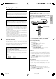
Before applying power Playable files with this unit Some files may be unable to be played correctly on this unit depending on the conditions of data, connection environment and the PC in use. 7 Video data (MOVIE file) [Max. file size 2GB] Preparations Item Detail Audio Format Extension MPEG1 -- MPG/MPEG Video resolution: 720 x 576 (Max.)/ Bitrate: 1.5 Mbps (Max.) MPEG1 LAYER 1 & 2 MPEG2 -- MPG/MPEG Video resolution: 720 x 576 (Max.)/ Bitrate: 8 Mbps (Max.
Before applying power Contents Caution : Read the pages marked carefully to ensure safe operation. Receiver Operations Ambience effects .................................. 38 Surround modes ........................... 38 Virtual modes ............................... 40 Surround play ............................... 41 Convenient functions ........................... 43 Adjusting the sound ..................... 43 Display dimmer adjustment ......... 45 Sleep timer ...................................
Names and functions of parts Main unit TONE indicator, 96kHz fs indicator, AUTO DETECT indicator, DIGITAL indicator, Sleep Timer indicator Character information display CLIP indicator, MUTE indicator, DUAL SOURCE indicator Preparations •••••••••••••••••••• •••••••••••••••••••• •••••••••••••••••••• •••••••••••••••••••• Dolby Virtual Speaker indicator, Dolby Headphone indicator, ACTIVE EQ indicator, AUTO indicator, ST.
Names and functions of parts Remote control unit This remote control unit can be use not only for Kenwood products but also for other non-Kenwood products by setting the appropriate manufacturer’s setup codes. ‰ For the U.S.A., Canada and Australia: RC-R0826 For Europe : RC-R0826E 4 DEF 3 P.
Names and functions of parts 0 ¢ / 4 keys º Setup key Use to perform the network server operations. UŒ Use to operate the CD, DVD or MD component. „ CH +/- keys Top Menu key Use to select the channels. „ Use to operate the DVD component. „ Preparations ! Mute key Use to temporarily mute the sound. ¤ Sound key Use to adjust the sound quality and the ambience effects. ⁄¤e @ TV VOL +/- keys „ Use to adjust the TV’s volume. Use to perform the network setup or speaker setup.
Setting up the system Input mode settings CAUTION Make sure that the power cord plug is disconnected from the AC wall outlet before proceeding to connections. Also be sure to disconnect the power cord plug from the AC wall outlet before changing connections. For the connections of other system components, see pages 10 to 17. VIDEO 1, VIDEO 2, AUX and GAME are full auto. After completing connections and turning on the receiver, follow the steps below.
Setting up the system Connecting wireless LAN When not using a broadband router or hub, connect this unit directly to the PC using a cross Ethernet cable. In this case, it is required to set the IP address and subnet mask manually. ª Connect the wireless Ethernet bridge to the ETHERNET jack on the rear panel.
Setting up the system Connecting a DVD player If you have connected a DVD player to the receiver with digital connection, be sure to read the "Input mode settings", "Re-assignment of rear panel jacks" section carefully.
Setting up the system Connecting video components, audio components Preparations Audio components Connecting video components (COMPONENT VIDEO) If you have connected the receiver to a video component with COMPONENT jacks, you can get a better picture quality than by connecting to the S VIDEO jacks.
Setting up the system Digital connections The digital in jacks can accept DTS,Dolby Digital,or PCM Connecting video components (S VIDEO) nents with S VIDEO IN/OUT jacks. ¶ If you use the S VIDEO jacks to connect your video playback connection,be sure to read the "Input mode settings", "Re-assignment of rear panel jacks" section carefully. 9∞ components, be sure to use the S VIDEO jacks when connecting your monitor and video recording components.
Setting up the system Connecting the speakers Whether each speaker is connected properly can be confirmed by outputting the test tone and checking if each speaker channel outputs audio. For details, see "Speaker settings" (Step 6 Adjust the speaker volume level). £ Preparations CAUTION Make sure that the power cord plug is disconnected from the AC wall outlet before proceeding to speaker cord connections.
Setting up the system Connecting the speaker terminals Front 1 Strip coating. ¶ Never short circuit the + and – speaker cords. ¶ If the left and right speakers are connected inversely or the speaker cords are connected with reversed polarity, the sound will be unnatural with ambiguous acoustic imaging. Be sure to connect the speakers correctly. 3 Insert. Speaker impedance 2 Loosen.
Setting up the system PRE OUT jacks connections Connecting to the GAME jacks / FRONT AUX jacks The receiver has additional PRE OUT jacks. Note that the output from the PRE OUT jacks needs to be connected to an external power amplifier. If you want to connect surround back speakers to these jacks, be always sure to connect two surround back speakers for the left and right.
Setting up the system Connecting the antennas Preparing the remote control The broadcast reception cannot be made unless the antennas are connected. Connect the antennas correctly as instructed below. AM loop antenna 1 Remove the cover. 2 Insert the batteries. Preparations The supplied loop antenna is for use indoors. Place it as far as possible from the receiver, TV set, speaker cords and power cord, and adjust the direction for best reception.
Let’s play DVD video software STEP 1 Connect the speakers, TV and DVD to the receiver Preparations For details, see "Setting up the system" 9 ~ ^ CAUTION Make sure that the power cord plug is disconnected from the AC wall outlet before proceeding to speaker cord connections. If the conductor wires on the extremity of speaker cord are untwisted, there is a risk of short-circuiting. Be sure to twist them well before connecting the speaker cord.
Let’s play DVD video software STEP 2 Set up the speakers POWER ON/STANDBY ON/STANDBY For details, see "Speaker settings" . ) ~ ¢ INPUT SELECTOR SETUP 2 Press , press or . to select "SPEAKER SETUP" and press .
Preparing for playback Speaker settings 2 Use the MULTI CONTROL @/ # (or the Multi @/ # keys) to To enable you to obtain optimum enjoyment from the receiver’s listening select “SETUP”, and press the ENTER (or the Enter key) . modes, make sure to complete the speaker settings (subwoofer, front, center, surround and surround back speakers) as described below. WARNING Preparations Could not detect server. Please chek following item. ENTER MULTI CONTROL %/fi/@/# POWER ON/STANDBY ON/STANDBY 1.
Preparing for playback 4 Select the setup method. Speaker Setup If you selected “Custom” in the above: 1 Select “Speaker Setup” and press the ENTER key (or the Enter key) to select the speaker setup method. 2 Use the MULTI CONTROL @ / # (or the Multi @ / # keys) for the following displays. Press the ENTER (or the Enter key) to proceed to detailed setups. After this, continue the procedure from step 5. The flow of the SETUP is as follows; SPEAKER SETUP HTB 1 HTB 2 HTB 3 Custom 6.1ch 5.1ch 6.
Preparing for playback 2 “Front Normal”: Preparations Average size front speakers are connected to the receiver. ÷ When the subwoofer setting is “Subwoofer On”, front speakers setting is “Front Large” and a stereo source is played, the low frequencies may be reproduced through the front speakers and no audio output from the subwoofer in certain listen modes. In this case, set the subwoofer re-mix setting in step # to “SW Re-mix On” to output the low frequencies from the subwoofer.
Preparing for playback 6 Adjust the speaker volume level. Speaker Level Test Tone Auto From your usual listening position, adjust the volume levels. The Left volume levels from each speaker should be the same. ÷ In this step 6, only the speaker channels that have been set 0 dB and require the volume level adjustment are displayed.
Preparing for playback 1 Use the MULTI CONTROL @ / # (or the Multi @ / # keys) to select “Speaker Distance” on setup displays, and press the ENTER (or the Enter key). 2 Use the MULTI CONTROL @ / # (or the Multi @ / # key) to select the unit and press the ENTER (or the Enter key). Preparations Feet 0dB ÷ The LFE LEVEL is adjusted from 0dB to -10dB in 1dB step decrements. Speaker Distance Meters RECEIVER SETUP LFE LEVL EL 3 Press the ENTER (or the Enter key) again to return to the main setup displays.
Preparing for playback Re-assignment of rear panel jacks Assignment The assignment of the input selector positions to the digital audio and component video input jacks can be changed as desired. 3 Use the MULTI CONTROL @/# (or the Multi @/# key) to select the input jack name and then press the MULTI CONTROL % /fi (or the Multi % /fi key) to select the input selector position.
Preparing for playback 3 Use the MULTI CONTROL %/fi (or the Multi %/fi keys) to select Network settings “Network Setup”, and press the ENTER (or the Enter key) . This unit can be connected to a PC through a LAN circuit. It is required to set up the network before connecting this unit to the PC.
Preparing for playback “Main” Setting Video Format Composite Output S Video Output Component output 1 NTSC CVBS Y/C ---- video or photo data in PC that has been input through the network, setting of the screen saver, setting of the black level, and updating of the firmware.
Preparing for playback "Black Level Setup” Setting: This setting item is used to set the black level. Network Setup Preparations NET LINK Back Back Back Main Menu Language 7.5 IRE IP Video Out 0 IRE Screen Saver Black Level Setup Fifmware Update 1 "7.5 IRE": Standard black level for the USA and Canada. 2 "0 IRE": Standard black level for Europe and Australia. "Firmware Update”: Refer to page 83 for Firmware Update. 28 EN *5489/18-29/EN 28 04.7.
Preparing for playback ”Subnet Mask” Setting: “IP” Setting Enter the subnet mask, which is issued by the provider, using the numeric keys. (It is usually 255.255.255.0.) The default setups are as follows. Network Setup NET LINK Back Back "Subnet Mask" Setting: "255.255.255.0" Main Obtaining Auto IP IP Address Subnet Mask Automatic setting: MAC Address To set the IP address automatically, set item” Obtaining Address” to ÷ It is recommended to set the subnet mask of “Auto”.
Normal playback Listening to a source component Some preparatory steps are needed before starting playback. POWER ON/STANDBY ON/STANDBY INPUT SELECTOR INPUT SELECTOR VOLUME CONTROL RCV Mode Input selector keys Input selector keys POWER RCVR Receiver Operations Input Mode VOL + / − Turning on the receiver 1 Press the INPUT SELECTOR key (or the Input selector keys/ 1 Turn on the power to the related components.
Normal playback Listening with headphones Adjusting the sound DUAL SOURCE VOLUME 5/∞ DUAL SOURCE INPUT VOLUME CONTROL MULTI CONTROL %/fi/@/# ENTER PHONES VOLUME CONTROL "DUAL SRC" indicator DUAL SOURCE ON/OFF RCV Mode Multi %/fi/@/# 1 Connect headphones to the PHONES jack. Enter Input Mode Mute / Active EQ 2 Use the VOLUME CONTROL knob (or the VOL +/– keys) to adjust the volume.
Normal playback Input level adjustment (analog sources only) ACTIVE EQ mode If the input level of an analog source signal is too high, the "CLIP" indicator will lights up to indicate the source signal. Adjust the input level. You can enjoy a more impressive sound effect when ACTIVE EQ is 1 Press the RCV Mode key on the remote control unit to set Press the Active EQ key for the following selections: 1 "ACTIVE EQ MUSIC" : (The "ACTIVE EQ" indicator lights up) it to the receiver control mode.
Recording Analog sources INPUT SELECTOR DVD Stereo DIGITAL VOL -75dB ↓ 1 Use the INPUT SELECTOR key (or the input selector key) to select the source (other than "VIDEO 1") you want to record. 2 Put the component connected to the VIDEO 1 jacks to the record-pause mode. 3 Start playback, then start recording. REC VOL MODE -75dB The display switches automatically. 4 Start playback, then start recording. Receiver Operations ÷ Recording may not be normal for some video software.
Listening to radio broadcasts The receiver can store up to 40 stations in the memory and recall them by one-touch operation. Radio stations can be classified into RDS (Radio Data System) stations and other stations. To listen to or store RDS stations in the preset memory see "Using RDS (Radio Data System) (For Europe)".
Listening to radio broadcasts Receiving preset stations Receiving preset stations in order (P.CALL) INPUT SELECTOR INPUT SELECTOR MULTI CONTROL @/# TUNER TUNER P.Call @/# Numeric keys 1 Use the INPUT SELECTOR key (or the TUNER key) to select tune as the source. 2 Enter the number of the preset station you want to receive (up to "40"). 2 Use the MULTI CONTROL @ / # (or the P.
Using RDS (Radio Data System) (For Europe only) RDS is a system that transmits useful information (in the form of digital data) for FM broadcasts along with the broadcast signal. Tuners and Using the RDS Disp. (Display) key receivers designed for RDS reception can extract the information from the broadcast signal for use with various functions, such as automatic TUNER display of the station name.
Using RDS (Radio Data System) (For Europe only) Presetting RDS stations (RDS AUTO MEMORY) 1 Press the PTY key to activate the PTY search mode. Lights up This function automatically stores up to 40 RDS stations in the preset memory. In order to use the PTY function, the RDS stations must be stored in the preset memory using the RDS Auto Memory function. PTY 1 Use the INPUT SELECTOR key (or the TUNER key) to select SELECT News VOL -75dB tune as the source.
Ambience effects This receiver is equipped with listening modes that allow you to enjoy an enhanced sonic ambience with a variety of video sources. In order to obtain the optimum effect from the surround modes, make sure to input the proper speaker settings beforehand.
Ambience effects DTS-ES DTS The DTS-ES (Digital Theater System-Extended Surround) represents 6.1-channel Discrete Surround format, expanding upon 5.1 surround. DTS-ES format is a 6.1 channel sound system for movie theaters that includes an additional surround center channel matrixed within surround left and surround right. It’s compatible on predecessor DTS 5.1 system. The extra channel allows more accurate placement and steering of sound accross the rear soundstage.
Ambience effects Virtual modes Dolby Virtual Speaker The Dolby Virtual Speaker features a virtual surround sound field. This implements an effect as if there are multiple speakers in the listening room. The following modes allow you to enjoy powerful surround audio even when you use only two speakers or listen through headphones. ÷ In the Dolby Virtual Speaker and Dolby Headphone modes, only the listen modes for 2 channels can be selected.
Ambience effects Surround play The desired listen mode can be selected according to the input signal. "Dolby D" indicator "DTS" indicator INPUT SELECTOR Listen modes available with Dolby Digital EX or Dolby Digital playback: ("Dolby D" indicator lights up) Main example of medium: Multi-channel digital source such as DVD.
Ambience effects Listen modes available with analog or PCM playback: Main example of medium: Digital sources including DVD 96 kHz linear PCM and CD. Analog source such as VCR or radio broadcasting. 1 "Dolby PL IIx Movie": DOLBY PRO LOGIC IIx surround MOVIE mode *1 2 "Dolby PL IIx Music": Dolby Digital Surround EX compliant disc : Dolby Digital Surround EX compliant disc contains identification signals.
Convenient functions You can make further adjustments to the sound while listening to playback in the surround mode. ÷ The mode using Sound key is defeated when the REC MODE is ON. ‹ LISTEN MODE Adjusting the volume level of each channel The volume levels of the center speaker, subwoofer, surround speaker and surround back speaker channels can be adjusted during playback. 1 Press the RCV Mode key on the remote control unit to set it to the receiver control mode.
Convenient functions Switching between main audio and sub audio (DOLBY DIGITAL mode only) 4 Use the MULTI CONTROL % / fi (or the Multi % / fi) to adjust the soundfield towards the rear or the front. Soundfield is adjusted towards the front. When listening to audio multiplex broadcasting such as two-language SOUND DIMENSION satellite digital broadcasting, the main and sub audio can be switched over. 1 Press the RCV Mode key on the remote control unit to set it to the receiver control mode.
Convenient functions Center Image mode (Only when the input signal is a 2-channel Display dimmer adjustment signal in the DTS NEO:6 MUSIC mode.) The dimmer function lets you select the brightness of the receiver's In the CENTER IMAGE setting mode of the NEO:6 MUSIC listen mode, display. You might find this useful if you darken your room to watch movies or listen to music.
Installing KENWOOD PC SERVER By installing the application KENWOOD PC SERVER in a PC, the data stored in the PC can be imported in the libraries for listening to or viewing music, movie and photographic data in the PC on the libraries. It is first necessary to connect the PC to this unit and set it up. 0§ Minimum requirements Operating system (OS): Windows XP Professional SP1, Windows XP Home Edition SP1, Windows 2000 Professional SP4 or after. Be sure to install the Service Pack for each OS.
Installing KENWOOD PC SERVER Uninstalling KENWOOD PC SERVER Updating KENWOOD PC SERVER When the software is no longer necessary, the software program can be removed by executing uninstallation. Be sure to exit from the software before proceeding to its uninstallation.
Operating KENWOOD PC SERVER Double-click on shortcut icon KENWOOD PC SERVER. on the desktop to launch the Do not attempt to launch KENWOOD PC SERVER more than once. Names and functions of window components 1 2 3 [BGM] button: Click on this button to link music with playback of a photo image. (Used only when the [PHOTO LIBRARY] is selected.) [SAVE] button: Click on this button to save the library list window data and let this unit recognize the contents of the corresponding library.
Operating KENWOOD PC SERVER When MUSIC files or PHOTO files are imported as “Temporary”: Only the files stored in the folders in the highest layer below the specified folders are imported. (The files located in folders below the folders in the highest layer cannot be played back.) MUSIC or Import of contents The contents of the PC can be imported in each library. To select a library, click on the [MOVIE], [MUSIC] or [PHOTO] tag. For the data types that can be imported, see “Playable files with this unit”.
Operating KENWOOD PC SERVER How to add additional information: The additional information for each content displayed in the library list window (“TITLE”, “STARS” and “YEAR”) can be edited. ÷ Some characters may be unable to be displayed in the library list on this unit. Importing contents in the [MUSIC LIBRARY] Click on the [MUSIC] tag to select the [MUSIC LIBRARY]. ÷ It is also possible to select multiple contents and drag & drop them together.
Operating KENWOOD PC SERVER Operation of import by selecting a folder: When a genre box is selected in the library box (field on the bottom left), a new album box is created and the contents in the folder selected in the library list window (field on the top right) are imported in the album box. (At this time, the album box is given the same name as the folder.
Operating KENWOOD PC SERVER When an album box is selected in the library box (field on the bottom left), the content(s) selected in the library list window (field on the top right) are imported in the album box. (One or multiple contents can be selected and imported.) Importing contents in the [PHOTO LIBRARY] Click on the [PHOTO] tag to select the [PHOTO LIBRARY]. Genre box [PHOTO] tag [IMPORT] button [SAVE] button 1 Select the genre box or album box for the contents to be imported.
Operating KENWOOD PC SERVER Linking BGM (BackGround Music) for SLIDE SHOW How to add an album box: Select the genre box to which you want to add an album box click Contents in the [MUSIC LIBRARY] can be linked to the contents in the the mouse right button. When a pull-down menu is displayed, select [Add Album]. [PHOTO LIBRARY]. When the photo images are played in slide show on this unit, the linked music files are played with the photo images as their background music.
Playback of Network Server When the KENWOOD PC SERVER software is installed in the PC, libraries can be constructed by grouping contents and their contents can be played back. The contents should be edited and/or deleted before connection to the PC server. If there is no server that can be logged in, the following warning message is displayed. POWER ON/STANDBY WARNING ON/STANDBY INPUT SELECTOR Could not detect server. Please chek following item. 1. Starting server 2. Starting PC application 3.
Playback of Network Server 3 Select the contents to be played in the library display. The library display for the library selected in step 2 is displayed. When the "MOVIE LIBRARY" has been selected : When the "MUSIC LIBRARY" has been selected : 1 Use the MULTI CONTROL %/fi/@ / # (or the Multi %/ fi/@ / # keys) to select the genre icon. Text information 1 Use the MULTI CONTROL %/fi/@ / # (or the Multi %/ fi/@ / # keys) to select the genre icon. MUSIC NET LINK PC Server 1 The P.
Playback of Network Server 3 Use the MULTI CONTROL %/fi/@ / # (or the Multi %/fi/@ / # keys) to select the contents icon, and press the ENTER (or the Enter key). (The same operation is also available by selecting a contents icon and pressing the 6 key.) Text information A B C D July BGM: Date: E Location: Genre: 2004 ÷ Press the Return key to return to the previous display. A Album B BGM (BackGround Music) C Date MUSIC NET LINK PC Server 1 The P.
Playback of Network Server Operation keys of the playback display Switching the playback modes The following operations are available on the playback display. (Some operations may be unavailable depending on the played content.) The playback modes can be switched on the playback display. However, some playback modes may be unavailable depending on the 7 STOP LIBRARY INFO MOVIE MUSIC played content. Press the P.MODE key during playback or pause. Press the key for the following selects.
Playback of Network Server Switching the video outputs Displaying the library list MOVIE MUSIC If the video format used by the content does not match that used by the TV monitor, the output of the content may be abnormal. To obtain a normal video output, switch the video output of this unit. Network Operations During stop status, press the Video Out key to switch the video output signals as shown below.
Playback of Memory Card Contents in a memory card, such as photo images captured using a digital camera, can be played back on this unit. (JPEG format only) Layers which can be played back Files in folders within the second layer can be played back. Types of memory cards with which operation has been confirmed CompactFlash ÷ SanDisk SDCFB-32-801 (32 MB) SDCFB-128-801 (128 MB) ÷ TDK ÷ I-O DATA TC064WA (64 MB) CFS-64MX (64 MB) CFS-256MX (256 MB) Memory Card Playback possible. Playback impossible.
Playback of Memory Card 1 Load the memory card data. 3 Select the contents to be played in the “PHOTO FOLDER” Use the INPUT SELECTOR key (or the Memory Card key) to select "MEMORY CARD". display. The hierarchy of data recorded in the memory card is displayed. When the “MEMORY CARD” input is selected, the OSD function on the TV screen is activated and the data in the memory card is loaded in this unit.
Playback of Memory card Operation keys of the playback display Zoom-up playback The following operations are available on the playback display. (Some operations may be unavailable depending on the played content.) Photo contents can be zoomed up when they are played. 7 STOP Press the Zoom key during playback of a photo content to magnify the image. Press the key for the following selects. x 1.25 = x 1.5 = x 1.75 = x 2 = x 2.25 = x 2.5 = x 2.75 = x 3 = x 3.25 = x 3.5 = x 3.75 = x 4 = x 1 = x 1.25 = ...
Basic remote control operations for other components The remote control supplied with this receiver is also capable of controlling components from a variety of manufacturers once you register the appropriate setup codes into the remote control unit. Low battery warning Replace all two batteries with new ones when you notice a shortening of the distance from which the remote control will operate. The remote control is designed to retain setup codes in memory while you change batteries.
Basic remote control operations for other components Checking the codes Operating other components The 4-digit setup codes registered in the input selector keys can be checked as follows. This operation lets you operate the registered components. 1 Press the input selector key in which the setup code of the desired component is registered. 2 Press and hold the Remote Setup key until the LED blinks twice, then release the Remote Setup key.
Basic remote control operations for other components Setup code chart (RC-R0826) (For U.S.A., Canada and Australia) Even when a component is manufactured by a maker listed in the setup code chart, it may be unable to be registered depending on the model and year of production. Also, when a setup code of a non-KENWOOD maker is registered, certain component models may be unable to be controlled or only the limited functions may be controllable.
Basic remote control operations for other components TV TV (Continued) Setup codes Maker Setup codes Admiral Aiko Aiwa Akai Albatron America Action Ampro Anam AOC Apex Digital Audiovox Bell & Howell Bradford Broksonic Candle Carnivale Carver Celebrity Celera Changhong Citizen Clarion Contec Craig Crosley Crown Curtis Mathes 0093, 0463 0092 1914 0812, 0702, 0030, 0672 0843 0180 0751 0180 0030 0748, 0765, 1943 0451, 0180, 0092 0154 0180 0236, 0463, 1935, 1929, 1938 0030 0030 0054 0000 0765 0765 0060, 003
Basic remote control operations for other components TV (Continued) TV/VCR Combination (Continued) Maker Setup codes Maker Setup codes Sheng Chia Sony Soundesign Squareview SSS Starlite Supreme SVA Sylvania Symphonic Tandy Technics Techwood Teknika Telefunken TMK TNCi Toshiba 0093 0000, 0834, 1925 0180, 0178 0171 0180 0180 0000 0748 0054, 0030, 0171, 1944, 1931 0180, 0171, 1913 0093 0250, 0051 0051 0054, 0180, 0150, 0060, 0092 0702 0178 0017 0154, 0156, 0060, 1935, 0650, 1704, 1945, 1356, 1936, 0832
Basic remote control operations for other components VCR (Continued) VCR (Continued) Maker Setup codes Maker Setup codes Kenwood Kodak LXI Magnavox Magnin Marantz Marta Matsushita MEI Memorex 0067 0035, 0037 0037 0035, 0039, 0081 0240 0035, 0081 0037 0035, 0162 0035 0035, 0162, 0037, 0048, 0039, 0047, 0240, 0104 0240, 0043 0240 0042 0067, 0043 0035, 0048 0240 0104, 0067 0037 0240 0035 0162, 0037, 0048, 0104 0184 0035, 0162, 0616 0035, 0037, 0240, 0042 0042 0035 0035, 0081, 0618 0037 0067 0081 0240 00
Basic remote control operations for other components DVD player (Continued) Maker Setup codes Qwestar RCA Rio Rotel Saitek Samsung Sanyo Sharp Shinsonic Sonic Blue Sony Sylvania Symphonic Technics Theta Digital Thrustmaster Toshiba Tredex Urban Concepts Yamaha Zenith 0651 0522, 0571, 0717, 0822 0869 0623 0731 0490, 0573, 1075, 0820 0670, 0873 0630 0533 0869 0864, 0772, 1033 0675 0675 0490 0571 0498 0503 0799 0503 0490, 0539, 0545 0503, 0591, 0869 Game Player Setup codes 0522 0533 Remote Control Maker
Basic remote control operations for other components Setup code chart (RC-R0826E) (For Europe) Even when a component is manufactured by a maker listed in the setup code chart, it may be unable to be registered depending on the model and year of production. Also, when a setup code of a non-KENWOOD maker is registered, certain component models may be unable to be controlled or only the limited functions may be controllable.
Basic remote control operations for other components Satellite Receivers (Continued) Maker Setup codes Maker Setup codes JVC Kathrein 0571, 0775 0173, 0200, 1057, 0658, 1221, 0123, 0249, 1058 0173 1296 1017 0299 0573 1083, 1017 0200 0750 0571 0853 1232 1216, 1210, 1334 1003 0571 1103 0879, 0642 0200 1322 0501 1239, 1143, 1119 0751, 0873, 1023, 1311, 1310, 1223, 1723, 0573 1232 1069 1100, 0501 0847, 1175, 0241, 0867, 1323, 0791 0571 0501 0879 0847, 1104, 1320 0853, 0200, 0805, 0133, 0750, 0571 0853, 035
Basic remote control operations for other components TV (Continued) TV (Continued) Setup codes Maker Setup codes Centurion Century Cimline Clarivox Clatronic Condor Conrac Contec Crosley Crown CS Electronics Cybertron Daewoo 0037 0087 0009 0037 0370 0370, 0320 0808 0036, 0009, 0216 0087 0037, 0370, 0579, 0009, 0418 0216 0218 0037, 0634, 1909, 0374, 1902, 0009, 0499 0218 0037 0009 0548, 0208 0037, 0516, 0072 0037 0037, 0009 0519 0217 0087, 0070 0735 0259 0037, 0548 0218, 0320 0009 1909, 0361, 0087 0037,
Basic remote control operations for other components TV (Continued) Maker Setup codes Memphis Metronic Metz MGA Micromaxx Microstar Minerva Minoka Mirror Mitsubishi Mivar MTC Multitech Myryad NEC Neckermann NEI Nikkai 0337 0625 0275, 0746, 0087, 0447, 0367 1907 0808 0808 0487, 0070 0412 1900 0036, 0108, 0087, 0512 0292, 0216, 0609, 0516 0512, 0349 0216, 0102, 0009 0556 0704, 0170, 1704 0556, 0037, 0087, 0349, 0191 0037, 0337 0037, 0264, 0218, 0035, 0216, 0337, 0072 0102 0548, 0606, 0361, 1912, 0480, 063
Basic remote control operations for other components TV (Continued) Maker Tensai Texet Thomson Thorn Tomashi Toshiba Triumph Uher Ultravox Universum Vestel Videotechnic Vision Voxson Wallis Waltham Watson Watt Radio Wega White Westinghouse Yoko Zanussi TV/DVD Combination Setup codes Maker Setup codes 0218, 0320 0218, 0216 0625, 0560, 0349, 0109 0037, 0361, 0190, 0499, 0035, 0104, 0072, 0193, 0512 0282 0036, 0618, 0508, 0035, 1508, 0070, 0718 0177, 0516 0320, 0206 0102 0037, 0264, 0370, 0104, 0346, 0492
Basic remote control operations for other components Remote Control VCR (Continued) VCR (Continued) Maker Setup codes Maker Setup codes Logik Luxor M Electronic Manesth Marantz Matsui Medion Memorex Metronic Metz Mitsubishi Multitech Murphy Myryad NEC Neckermann Nokia Nordmende Oceanic Okano Orion Osaki Otto Versand Palladium Panasonic Pathe Marconi Pentax Perdio Philips Phonola Pioneer Profitronic Proline Pye Quartz Quelle Radiola Reoc Rex Roadstar Saba Salora Samsung Sansui Sanyo SBR Schaub Lorenz
Basic remote control operations for other components DVD player (Continued) Game Player Setup codes Maker Setup codes 0774 0819 0741, 0591 0768 0783 0562 0746 0690 0723 0752 0712 0752 0521 0665 0730 0692 0672 0627 0747 0651 0490, 1010 0690 0539, 0646 0571, 0525, 0631 0686 0689 0763, 0748 0767 0752 0699 0689 0623 0573, 0744 0670 0783 0752 0718 0630 0633 0717 0766 0730, 0690 0772, 1533, 1033 0770, 0771 0759 0490 0825 0551, 0522 0665 0503, 1045 0799, 0843 0531, 0690 0591 0699 0686, 0696 0806 0709 1004 076
Basic remote control operations for other components DVD player, MD recorder, CD player & TV operations Refer to the following for the type of remote control operations available for each component. 1 Select the input source. 2 Press the keys corresponding to the operations you desire. Refer to the following sections for details. ÷ When pressing keys in succession, press each key firmly and be sure to wait at least 1 second before pressing the next key.
Basic remote control operations for other components VCR , Satellite receiver & Cable converter operations Refer to the following for the type of remote control operations available for each component. 1 Select the input source. 2 Press the keys corresponding to the operations you desire. Refer to the following sections for details. ÷ When pressing keys in succession, press each key firmly and be sure to wait at least 1 second before pressing the next key.
In case of difficulty Resetting the Microcomputer The microcomputer may malfunction (unit cannot be operated, or shows an erroneous display) if the power cord is unplugged while the power is ON, or due to some other external factor. If this happens, please try either procedure below. Reset to the factory default setups: Soft reset: This reset procedure allows the setups made by the user to be held without being reset. (For U.S.
In case of difficulty Amplifier Symptom Remedy No sound from the speakers. Sound is not output from the speaker, or their sound is very small. The standby indicator blinks and sound is not output. ÷ Connect them properly referring to "Connecting the speakers" $ ÷ If muting is ON, release it. ÷ If headphones are connected, disconnect them. ÷ Press the Input Mode key to select to full auto mode. ¤ ⁄ 9 ÷ Check if the assignment of digital audio input jacks is correct.
In case of difficulty Tuner Symptom Remedy Radio stations cannot be received. ÷ Connect an antenna properly. ÷ Set the broadcast band properly. ÷ Tune the frequency of the desired station. & › ÷ Install the outdoor antenna away from the road. Interference. ÷ Turn off the power to the appliance. ÷ Install the receiver farther away from the TV. A station which was preset cannot be received by pressing the corresponding ÷ Preset a station with a receivable frequency. numeric key.
Specifications (For U.S.A. and Canada) AUDIO section Rated power output during STEREO operation 70 watts per channel minimum RMS, both channels driven, at 8 Ω from 20 Hz to 20 kHz with no more than 0.7% total harmonic distortion. (FTC) 100 watts per channel minimum RMS, both channels driven, at 6 Ω from 20 Hz to 20 kHz with no more than 0.7% total harmonic distortion. Output level / impedance Composite (VIDEO 1, MONITOR OUT) ................. 1 Vp-p / 75 Ω S VIDEO (MONITOR OUT) Luminance signal ...........
Specifications (For Europe and Australia) AUDIO section VIDEO section For Europe Rated power output during STEREO operation ...... 100 W + 100 W DIN/IEC (20 Hz ~ 20 kHz, 0.7% T.H.D. at 6 Ω ) Effective power output during STEREO operation ..... 130 W + 130 W (1 kHz, 10% T.H.D. at 6 Ω ) For Australia Rated power output during STEREO operation Input sensitivity / impedance Composite (DVD, VIDEO 1, VIDEO 2, FRONT AUX, GAME) ..................................................................................
Firmware Update IMPORTANT: Be sure to update the KENWOOD PC SERVER sofware to the latest version before updating the Firmware. u The latest information and procedure to update your KENWOOD PC SERVER software and VRS-N8100 Firmware can be found in the "Technical Support" / "Service" section on the website of your resident country (if necessary you can find a link to your local website on www.kenwood.com ). Exit from all software that is currentry running.
For your records Record the serial number, found on the back of the unit, in the spaces designated on the warranty card, and in the space provided below. Refer to the model and serial numbers whenever you call upon your dealer for information or service on this product. Model __________________ Serial Number ________________________ *5489/78-84/EN 84 04.7.