
Manual
3-24 BHK-1/2-MG 121313
3.7.3.6 INSTRUMENT SUBSYSTEM
This subsystem controls the power supply's voltage and current outputs and allows compatibility
with other vendor’s products
3.7.3.7 STATUS SUBSYSTEM
This subsystem programs the power supply status register. The power supply has two groups of
status registers: Operation and Questionable. Each group consists of three registers: Condition,
Enable, and Event.
3.7.3.8 SYSTEM SUBSYSTEM
This subsystem controls the RS 232 port, as well as system errors, passwords, security, lan-
guage, beep, version and keyboard lockout
3.7.3.9 TRIGGER SUBSYSTEM
This subsystem controls the remote triggering of the power supply.
3.7.3.10 [SOURCE:]VOLTAGE AND [SOURCE:]CURRENT SUBSYSTEMS
These subsystems program the output voltage and current of the power supply.
3.7.3.11 CALIBRATE SUBSYSTEM
The BHK-MG series of power supplies support software calibration. A full calibration consist of a
voltage calibration and a current calibration. Both voltage and current calibrations consist of a
zero and a full scale calibration. There are two ways to perform the calibration: locally using the
front panel keys, or remotely sending commands through the GPIB bus. These two ways cannot
be combined.
In order to enter the calibration mode the correct calibration access code (password) must be
entered. If the password has been forgotten call the factory and a secret password (which has
been assigned to your power supply) will be provided. During the calibration, new calibration
data is computed which is then stored in the non volatile memory.
The equipment required for calibration is specified in PAR. 4.2.
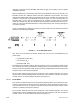
Because the voltage measured will be used as reference for calibration, the DVM itself must be
calibrated accurately. During voltage calibration, the voltage, overvoltage and voltage readback
are calibrated and during current calibration the current, overcurrent, current readback and 10
percent scale current readback are calibrated. The normal procedure is to calibrate voltage first
and then current. However, you do not have to do a complete calibration each time. If required,
you may calibrate only the voltage or the current and then proceed to saving the calibration
results. For voltage calibration all loads must be disconnected and the sense terminals con-
nected to the corresponding output terminals. The digital voltmeter will be connected to the out-
put of the power supply. For current calibration after disconnecting all loads an appropriate
shunt resistor will be connected across output terminals and the digital voltmeter will be con-
nected across the sense terminals of the shunt resistor.