
Manual


3-34 BHK-1/2-MG 121313
The following warnings and cautions apply to the analog programming terminals because the
analog control circuitry operates at the +OUTPUT potential and the common of the analog con-
trol circuitry is connected to the +OUT terminal (TB1) through the sensing resistor (Rs) of the
power supply.
• If the power supply is operating with +OUT terminal connected to ground, do not connect
grounded inputs or outputs of any external equipment to power supply analog program-
ming terminals. If this situation is unavoidable, connect the external equipment to a-c
source power using an isolating transformer. For external equipment with grounded out-
put only, use the uncommitted amplifier of the power supply in differential configuration.
• If the power supply is operating with –OUT terminal connected to ground, the external
programming source must be isolated up to the maximum output voltage plus 1KV. The
programming source must be either battery powered or powered through an isolation
transformer and feature “fully insulated controls and chassis.”
• If the power supply must operate isolated from ground (floating), any external equipment
connected to the ANALOG PROGRAMING TERMINALS must also be isolated (battery
operated or connected to a-c source power using an isolating transformer).
Safety Message
When the output is disabled, whether by the OUTPUT ON/OFF key, SCPI command via GPIB
or RS 232 interface, or via the Status and Remote On/Off Port, an internal solid-state switch sets
the voltage/current references to zero, resulting in zero output from the power supply. In the
case of the OUTPUT ON/OFF key or SCPI command, if the solid state switch fails, and the out-
put is higher than 8V, and the current is higher than 1mA, a shutdown sequence begins: the unit
beeps and flashes the message Power Down in XX sec for 10 seconds as XX counts down
from 10 to 0. After 10 seconds the input circuit breaker trips OFF. If the circuit breaker does not
trip OFF, BHK Failure is displayed on the LCD.
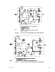
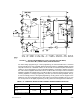
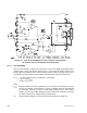
3.8.2 PROGRAMMING WITH EXTERNAL RESISTANCE
Figures 3-9 and 3-10 are simplified diagrams of the BHK-MG showing the jumper configuration
and external connections required for analog programming using an external resistance. Fig-
ures 3-9 shows programming of either output voltage when the unit is in voltage mode, or volt-
age limit when the unit is in current mode. Figure 3-10 is a similar diagram for programming
either output current when the unit is in current mode, or current limit when the unit is in voltage
mode.
WARNING