Doors.NET Reference Manual Welcome to Doors.NET Welcome to Doors.NET- a comprehensive software suite that addresses access control, intrusion monitoring, video integration, biometrics, and facility automation. Doors.NET is the flagship product for Keri Systems, Inc. and is a result of an experienced development and sales team, with feedback from focus groups, consultants, and end users. Doors.
Doors.NET Reference Manual 3. Performance figures and data quoted in this document are typical, and must be specifically confirmed by Keri Systems, Inc. before they become applicable to any tender, order, or contract. Document p/n: 01249-001 Software version 3.5.1.19 - Rev A Corporate Headquarters Keri Systems, Inc. 2305 Bering Drive San Jose, CA, USA 95131 Phone: 408-435-8400 Toll Free: 800-260-5265 E-mail: sales@kerisys.com Web: www.kerisys.
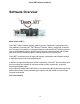
Doors.NET Reference Manual Software Overview What is Doors.NET? Doors.NET is Keri Systems' flagship software product. Designed to manage Keri Systems hardware, including NXT, NXT Mercury-Powered, Mercury controllers, as well as the PXL range of controllers. It is designed natively in Microsoft's .NET platform and utilizes an SQL database engine. With all instructions and communications with the database done through stored procedures, making response time lightning fast. Doors.
Doors.NET Reference Manual Doors.NET has a very intuitive interface, that will perhaps seem familiar if you have used Keri's Doors32 software. It has a similar Doors32-like operation, but with enhanced features and an updated look and feel. The interface can be used 'out of the box with its default layout settings, or it can be configured to individual preferences for daily use. The GUI supports multiple monitors.
Doors.NET Reference Manual software. It can be configured to run on a single PC or multiple PCs across a network depending upon the desired characteristics of the system. Software Installation The software can be installed either via the webinstaller - the files can be downloaded via the www.kerisys.com website, or it can be installed via the installation DVD - Which you can obtain from Keri Systems, free of charge.
Doors.NET Reference Manual Custom Credential Formats, Area Control, Host Schedules, System Calendar, Rollcall Client, and a Professional Report Client. The license key can be altered to allow for additional client connections, additional gateways or for increasing the capacity for supported cameras - Many of these additional features are covered in detail elsewhere within the Online Help.
Doors.NET Reference Manual Alerts can be easily setup in Doors.NET to automatically give an indication in the software when a certain event occurs. For example, if a panic button is pressed, if a secure door is forced open, if an Anti-Passback violation occurs, if a reader or a controller goes offline, if a tamper switch goes active, or if a motion detection sensor is activated.
Doors.NET Reference Manual Doors.Net supports an unlimited number of software users and user groups. User rights can be configured with limitations or they can have the same user rights as a system administrator. Anyone with administrator rights can add users, configure rights and assign those rights to other users.
Doors.NET Reference Manual updates in real-time as the cardholders move throughout the facility. An occupancy counter updates as cardholders enter or leave the area. Elevator control - Allows for an extremely cost-effective means of controlling elevators for various sized elevator applications (requires the use of NXT Mercury-Powered controllers and NXT 4x4 or GIOX modules). When using a 4x4 module on each controller bus up to 20 floors can be controlled per controller.
Doors.NET Reference Manual customers that have this feature enabled on their license). A number of new categories have been added to the traditional meeting, personal reminders, etc, that include backup, global linkage and direct hardware control. In addition, the Host Schedules use the Holidays that are scheduled in this calendar. A recurrence engine is also provided that allows you to configure recurring events with ease.
Doors.NET Reference Manual System Architecture Overview The core software module is the Application Server. This component communicates with the SQL database, client work stations, and software gateways that communicate with the access control hardware. It is a TCP socket server that accepts connections from both the gateways and clients, and provides a generic transport mechanism for any .NET class object, collection of those objects, or file.
Doors.NET Reference Manual The Doors.Net Gateway connects to up to 64 NXT controllers (256 reader capability, standard license, using 4 readers per NXT-4D controller) and communicates with the Application Server. Only 1 Gateway is allowed per computer.
Doors.NET Reference Manual What's New In This Release Doors.NET Version 3.5.1.
Doors.NET Reference Manual New Features New Hardware Release: l The GIOX (Greater I/O Board) has been released for use by NXT and Mercury Powered NXT controllers. The GIOX unit is made up of a back plane and a combination of Input and/or Output plug-in modules. The back plane handles up to 8 plug-in modules in any combination of input module or output module. Input modules have 8 inputs and Output modules have 8 outputs.
Doors.NET Reference Manual l None at this time. Unique to ASSA WiFi/POE Lock Hardware: l None at this time. Unique to IR/Schlage Lock Hardware: l None at this time. Program Improvements For All Hardware Platforms: l l l l l l l l Corrected an issue that prevented the Auto Config window from closing if the installer opted not to complete the Auto Config process. Added the ability to clear the Roll Call list at a specific time every day.
Doors.NET Reference Manual Unique to PXL Controllers: l l l l l l Made a number of gateway improvements to accommodate network timing conditions in medium to large controller networks (typically 20 controllers or more). Corrected an issue with single-door applications using two readers. Operating parameters assigned to the second reader are now properly applied to that reader. Implemented a check to prevent multiple back-to-back Update Network requests from being executed.
Doors.NET Reference Manual l l Corrected an issue with event display filtering. Implemented new WiFi/POE drivers provided by ASSA. Driver version is now 4.4. NOTE: If you are upgrading an existing ASSA WiFi/POE installation you must manually remove the existing ASSA driver (version 1.2) before running the Doors.NET installer. Unique to IR/Schlage Hardware: l l l l l Corrected the display of the Interior Push Button indicator. Corrected temp LED commands. Corrected operation in Card OR PIN mode.
Doors.NET Reference Manual l l PXL controllers require firmware revision 8.6.09. Legacy PXL controllers should be at firmware revision 8.4.49 or greater (this firmware revision is programmed with the current U.S. Daylight Savings Time dates and has the complete PXL implementation of Anti-Passback). For Mercury Powered NXT controllers and Mercury Hardware: l Mercury Powered NXT controllers require new firmware revision 1.185. Firmware Upgrades NXT Firmware v2.05.
Doors.NET Reference Manual Translations Completed Translations: l l l l l l l l l Chinese (Simplified) Chinese (Traditional/Taiwan) English (UK) French (France) Polish Russian Slovenian Spanish (Castilian) Turkish Translations Pending Updates *: l l l l Arabic (UAE) Dutch (Belgium) French (Belgium) Italian * These translation file sets are not yet complete pending submissions from our translators.
Doors.NET Reference Manual Release History Previous Releases: l l l l l l l l l l v3.5.1.18 v3.5.1.17 v3.5.1.16 v3.5.1.15 v3.5.1.14 v3.5.1.12 - SP-2 v3.5.1.11 v3.5.1.10 v3.5.1.9 v3.5.1.8 Doors.NET Version 3.5.1.
Doors.NET Reference Manual Operating System 2003 2008 2008 R2 2012 32-Bit Yes Yes Yes N/A 64-Bit Yes Yes Yes Yes (1) The ASSA gateway is not yet Windows 8 compatible for IP locks (Wifi and POE). The software installer will not allow the ASSA gateway to be installed if the operating system is Windows 8. NOTE: Doors.Net software IS NOT compatible with any Home/Basic version of Windows XP, Windows Vista, Windows 7, or Windows 8.
Doors.NET Reference Manual including varying restriction levels of lock and unlock and the ability to assign/unassign specific doors. The Situation Manager requires the master controller always be online with the host PC. Unique to Keri NXT Mercury Powered Controllers and Mercury Hardware: l None at this time. Unique to ASSA Lock Hardware: l None at this time.
Doors.NET Reference Manual Unique to PXL Controllers: NOTE: For PXL installations, Keri strongly recommends upgrading to the 3.5.1.18 release to take advantage of the improvements made for data throughput and event collection, and for master/slave controller updating. l l l l l l l l l Made multiple improvements in data handling and event collection in the gateway, increasing data throughput when multiple master controllers are connected.
Doors.NET Reference Manual l l If you deleted an elevator controller from the hardware tree before deleting elevator access groups, you could not remove the elevator access groups from the access group list. A new communication channel for a controller is only created if a unique IP address is provided and controller/channel is enabled. ASSA Gateway: l l l Corrected an issue when adding a new access group. The ASSA gateway required a restart to accept the access group.
Doors.NET Reference Manual Firmware Requirements For NXT controllers and peripherals: l Standard NXT controllers require new firmware revision 2.05.27. l NXT Readers require firmware revision 3.00.01 or greater. l Reader Interface Modules (RIMs) require firmware revision 3.02.05. l 4x4 I/O Modules require firmware revision 3.00.02. For PXL: l PXL controllers require new firmware revision 8.6.09. l Legacy PXL controllers should be at firmware revision 8.4.
Doors.NET Reference Manual l l l l l l French (France) Polish Russian Slovenian Spanish (Castilian) Turkish Translations Pending Updates *: l l l l Arabic (UAE) Dutch (Belgium) French (Belgium) Italian * These translation file sets are not yet complete pending submissions from our translators. If you use these translations you will find mislabeled and/or non-translated ribbon and menu fields in some sections of the program. Non-translated fields will be displayed in US English. Doors.NET Version 3.5.
Doors.NET Reference Manual Operating System Windows Server 2003 2008 2008 R2 2012 32-Bit 64-Bit Yes Yes Yes N/A Yes Yes Yes Yes (1) The ASSA gateway is not yet Windows 8 compatible for IP locks (Wifi and POE). The software installer will not allow the ASSA gateway to be installed if the operating system is Windows 8. NOTE: Doors.Net software IS NOT compatible with any Home/Basic version of Windows XP, Windows Vista, Windows 7, or Windows 8.
Doors.NET Reference Manual l l l An Elevator Override Schedule feature has been added allowing the enabling of floor access via a schedule. This feature is accessible when the Advanced View is enabled. An "Honor Day of the Week" option has been added to schedule intervals. This is used if you need specific schedule intervals to be activated regardless of if the day is a holiday (when all intervals would have been disabled). Added Door Forced and Door Held alarm options to the Door property grid.
Doors.NET Reference Manual l l Added the ability to set operator permissions for viewing the status menu. Previously, all operators could view the status menu; now permission can be either granted or denied per operator. Corrected an issue that prevented Panel type hardware Reports from being generated. Unique to NXT Controllers: l l l Extended the maximum strike time. The program had been limiting the maximum strike time to 255 seconds; this is much too short a time.
Doors.NET Reference Manual l l Corrected an issue with the "Check With Host" feature. If a reader has this feature enabled the controller will check with the host system to confirm access permission. If not enabled, the controller is free to use the permissions already programmed in. Corrected an issue with Master Holidays. Once a Master Holiday schedule was set, changes in Master Holiday schedules were not being automatically updated to the controllers.
Doors.NET Reference Manual Firmware Requirements For NXT controllers and peripherals: l Standard NXT controllers require new firmware revision 2.05.25. l NXT Readers require current firmware revision 3.01.01. l Reader Interface Modules (RIMs) require current firmware revision 3.02.05. l 4x4 I/O Modules require current firmware revision 3.00.02. For PXL: l PXL controllers require current firmware revision 8.6.04 l Legacy PXL controllers should be at firmware revision 8.4.
Doors.NET Reference Manual Mercury Hardware Firmware v1.173 l Provides support for the new IPv6 standard. l Improves the controller's network response when an Ethernet cable is unplugged. l Improves the controller's ability to recover from large, rogue data packets. l Adds SNMP capability.
Doors.NET Reference Manual Doors.NET IS compatible with the Business, Professional, Ultimate, and Enterprise versions (both 32-bit and 64-bit) of Windows XP, Windows Vista, and Windows 7; as well as Windows Server versions 2003 and 2008 (both 32-bit and 64-bit). New Features For All Hardware Platforms: l An Onvif video plug-in is now available. Unique to Keri PXL Controllers: l A database conversion process is now available to transfer Doors32/PXL databases into Doors.NET.
Doors.NET Reference Manual l l l l Corrected a date-check issue with appointment schedules that would not allow an appointment schedule to cross midnight. Added the ability to show/hide Alerts in the operator permissions grid. Modified the License Manager to allow Demo mode to activate regardless of the availability of an Internet connection. Changed the Block Enrollment default for credential access from "Total Access" to "Unassigned." Unique to NXT Controllers: l None at this time.
Doors.NET Reference Manual l Legacy PXL controllers should be at firmware revision 8.4.49 or greater (this minimum firmware revision is programmed with the current U.S. Daylight Savings Time dates) NOTE: Legacy PXL controllers require the PXL Gateway license to be used with Doors.NET software. For Mercury Inside (MSC) NXT controllers: l MSC NXT controllers require current MSC firmware revision 1.01.40. Firmware Upgrades None at this time.
Doors.NET Reference Manual Doors.NET Version 3.5.1.15 Operating System Requirements Doors.Net software IS NOT compatible with any Home version of Windows XP, Windows Vista, and Windows 7. This is due to networking restrictions built into the Home versions of Windows operating systems. Doors.
Doors.NET Reference Manual l l l l l l l l l l l Corrected an issue when reassigning a door strike from a controller to a 4x4 I/O module. The reader assignment list was not being filled with all the available readers. Corrected an issue in actively updating Access Group information between clients when multiple clients are open.
Doors.NET Reference Manual l The program now requires that a new cardholder entry be saved before attaching a photo to that cardholder. This ensures the new cardholder entry is created in the database, providing the proper database location for the photo to be attached. Unique to NXT Controllers: l l l l l l l Corrected an issue when in Lock-down Mode. RTE requests were being performed by the system when they should not be.
Doors.NET Reference Manual l l l Added firmware upgrade status messages to provide active feedback during an upgrade. Added options to the System Calendar allowing a Full Cardholder Download and an Update Network to be scheduled operations. Corrected an issue with setting a vacation date. Vacation Settings are used to temporarily disable a credential when a cardholder goes on vacation. The program originally assumed a vacation would start at some date in the future and run some number of days.
Doors.NET Reference Manual Mercury Powered NXT Firmware (MSC) v1.01.40 l l Corrects an issue with Assa Aperio wireless lock hubs that could interrupt communication. Provides a method for temporary access to the web user interface. When a new web user is added the default admin account is disabled. Should you lose the web user password you could be permanently locked out of the controller. Now you can press the S1 switch twice to re-enable the default web user admin account for 5 minutes.
Doors.NET Reference Manual l l l l The NXT Reader requires new firmware revision 3.01.01 specifically to enable the In/Out reader function. If this feature is not being used then the previous version of reader firmware (v3.00.01) continues to be fully functional. The Reader Interface Module (RIM) requires new firmware revision 3.02.05. The 4x4 I/O Module requires new firmware revision 3.00.02. The Mercury Inside gateway (MSC) requires that NXT controllers have new MSC firmware revision 136.
Doors.NET Reference Manual l l l l l l l l l l l l l feature addition, requiring the user to repeat the activation process when Internet access is finally restored. Added a notification for the user such that if a Gateway is offline when a Synchronize Clocks command is performed a notification dialog appears to alert the user that the Gateway could not be synchronized.
Doors.NET Reference Manual l l l l l l l l l l l l l l l Corrected an issue with Access Groups that allowed multiple Reader assignments in an Access Group for Readers on buses 2, 3, or 4. Added time duration information to the Lock Out Duration parameter for keypad readers. The tool tip associated with this field now explicitly states the time out is in minutes. Removed the facility code field from the Credentials window for NXT credentials. NXT credentials do not use a facility code field.
Doors.NET Reference Manual l l l l l l l l l l l l l l l l l l Added more options to the context menus used when creating an email/SMS messaging macro. This makes it easier to include a greater variety of information to these types of messages. Corrected operator permissions when setting holidays or time schedules. An operator with view-only permission for these two fields was still able to add new holidays or time schedules.
Doors.NET Reference Manual l l l l l l l l l l l l l Card-Only to more secure Two-Card required, but would not switch back to the less secure option. Standardized the wording for all Situation Manager states and all related event messages. Corrected an issue where setting Operator Permissions did not correctly handle permissions for System Options.
Doors.NET Reference Manual l l l l l l l l l l l l l l Corrected an issue when creating monitoring filters. Certain filter types would not save properly, rendering those filters unavailable. Corrected an issue when applying either the Mask Forced or Mask Both filters. A Reader Contact - Door Closed event message would display in Live Events, but its corresponding Reader Contact - Door Opened event would not. Both events now appear in Live Events in proper order.
Doors.NET Reference Manual that output. This only applies to new reassignments. If you upgrade the software from a previous revision and have these types of reassignments applied, they correctly remain active. You just cannot make new assignments.
Doors.NET Reference Manual l Adds the ability to change the Server ID, Controller ID, and Network Data using Telnet commands. This feature can be useful when configuring Controllers that are spread out over a WAN. NXT Reader Firmware v3.01.01 l Provides support for In-door/Out-door Readers (also known as Master/Slave Readers).
Doors.NET Reference Manual NOTE: Due to networking restrictions built into the Home versions of Windows operating systems, Doors.Net software is NOT compatible with any Home version of Windows XP, Windows Vista, or Windows 7. Doors.NET IS compatible with the Business, Professional, and Ultimate versions (both 32-bit and 64-bit) of Windows XP, Windows Vista, and Windows 7.
Doors.NET Reference Manual Ingersoll-Rand / Schlage AD-Series wireless locks l Support for reverse bit patterns for specific types of Magstripe and Wiegand format readers Adds P-640 Wiegand keypad reader support. Adds more information when displaying Local Linkage states to better annunciate current status. Adds the ability to drag-and-drop controllers in the Hardware Browser. This makes it easy to move existing controllers to a new gateway during system expansion.
Doors.NET Reference Manual Program Improvements: l l l l l l l l l l l l Corrected typographical and display field errors in several program windows. Corrected information field sizing issues that appear when using non-English languages. Re-enabled sorting by Access Group for transaction reports. Please keep in mind that cardholders who are assigned to multiple Access Groups may not sort as expected.
Doors.NET Reference Manual l l l l l l l l l l l l l l l l l prompts the user to redefine that programming prior to removing the 4x4 from the system. Corrected an issue with Doors.Net/Eclipse installations when using the Windows 7 operating system. In certain systems the Doors.Net/Eclipse software could not retrieve the name assigned to the computer. Corrected SMS settings for Cingular and US Cellular carriers. Corrected an issue with the Confirm Alert button state on the host software.
Doors.NET Reference Manual l l l l l l l l Separated the operator permissions for viewing credential activation dates from viewing credentials themselves, creating two separate operator permissions. Disabled the ability to select a time interval for First Person In when the First Person In feature is not enabled. Standardized the Archive Service date/time value format. All archiving is now done in ISO 8601 format, eliminating confusion when reviewing data stored by the Archive Service.
Doors.NET Reference Manual NXT Firmware Version 2.05.16 l Corrected a controller power-up issue that could energize a 4x4 relay during the power up process. Doors.NET release version 3.5.1.11 New Features: l There are no new features included in this release. Program Improvements: l l l l l l l Corrected an issue with the Archive Service that caused the service to create an excessive number of databases in support of the archiving process.
Doors.NET Reference Manual The system calendar option is licensed separately but include more features than just the backup option. Program Improvements: l l l l l l l l l l l l l l l If a user executed the same save command, multiple times, back-to-back, command communication would fail and report a timeout. Checks have been implemented to filter out multiple instances of the same command.
Doors.NET Reference Manual Firmware Updates for Hardware Components: RIM v03.01.11 l Under certain conditions, typically when “hot-swapping” readers or in unusually EMI noisy environments, the RIM’s Data0 and Data1 lines could be pulled into a both-lines-low state. This is illegal per the Wiegand specification, and because of this it was not properly managed by the firmware. Changes were made in the firmware to recognize this state and prevent this condition from being processed.
Doors.NET Reference Manual l l l l l l l When setting operator permissions to View Only, certain permissions were not correctly applied. The Search Cardholder by Card Number option was not performing search operations correctly. When enrolling cardholders, the Imprint field could get locked out preventing input after selecting a credential from one cardholder and then selecting a different cardholder. The Local Linkages screen would not update properly following User Group name changes.
Doors.NET Reference Manual l l l l l l l Changing filter settings required a unique password and not the standard system administrator password. Now the system administrator password works for allowing these changes to be made. Corrected a screen refreshing issues that required a window close/open to see newly entered values. Expanded certain field name sizes to accommodate long name strings. Corrected an issue where you could not remove/replace a photo from the Photo Recall client.
Doors.NET Reference Manual Technical Support Keri's highly experienced and knowledgeable staff provides technical support worldwide. U.S. Support: l l l Office hours: Monday through Friday (6:00 AM to 5:00 PM, Pacific Time) Phone: 1-800-260-5265 or 1-408-435-8400 - When the phone greeting begins, press 2 to enter the Tech Support queue. techsupport@kerisys.com - We will respond within two working days, excluding Saturday and Sunday.
Doors.NET Reference Manual Software Installation Doors.NET installation and controller configuration is a three step process. Each of these steps has its own section, with controller configuration broken into separate documents per hardware type. 1. Install the software (see below), which will also automatically install Microsoft's SQL Server Express ® (a free SQL server program) if the PC does not already have SQL available. 2.
Doors.NET Reference Manual NOTE: Navigate to the DVD's root directory and run the autorun.exe program if this menu does not appear. l l l l l l l l Click the Keri Logo to open your web browser and visit the kerisys.com web site. Click View Release Notes to view a Readme.txt file with information on this software release. Click Install Software to install Doors.NET. Click Installation Document Set to open an Explorer window with a set of documents covering basic installation.
Doors.NET Reference Manual 3. Once started, the installer performs a quick installation file verification and prepares the file set for installation. 4. The Welcome Window appears when the installation is ready to begin.
Doors.NET Reference Manual 5. Review the version listing to confirm the revision of the software to be installed. 6. Click NEXT to continue to the License Agreement. NOTE: You must accept the terms of the License Agreement to install this software. Keri recommends reading through the License Agreement in its entirety before accepting the terms.
Doors.NET Reference Manual 7. Click the check-box to accept the License Agreement. 8. Click NEXT to enter Customer Registration information.
Doors.NET Reference Manual 9. Enter your User Name and (optionally) an Organization Name. 10. Click NEXT for Hardware Selection.
Doors.NET Reference Manual 11. Click the radio button corresponding to the controller type being used in the system. l Keri NXT for standard NXT controllers. l Keri NXT (Mercury Powered) and MSC for either NXT controllers using Mercury firmware or for Mercury hardware controllers. l Keri PXL for PXL controllers. 12. Click NEXT to select your Type of Installation.
Doors.NET Reference Manual 13. Click the Radio Button corresponding to your Type of Installation. l A Full Installation installs all software components for a standard installation onto the PC. l A Basic Installation installs only the user client onto the computer. l A Basic Installation with Hardware Driver installs the user client and the relevant hardware gateway onto the computer. Use this option if your user client is on a different subnet than the PC with the full installation.
Doors.NET Reference Manual 18. The default destination folder is listed in the destination folder field. Keri recommends using this folder for the software installation. If a different destination folder is desired than the default, you may use the Explorer window to locate the desired folder. Once located, double-click on the folder name to enter the folder name into the destination field. 19. Click NEXT to select the types of program shortcuts to be installed on the computer.
Doors.NET Reference Manual 20. Use the radio buttons to select if software access is to be granted to: l Current User Only (the user logged into the PC) l All Users of the Computer (any user logged into the PC) 21. Use the checkboxes to select any combination of: l Desktop icon l Start Menu folder l Quick Launch Toolbar 22. Click NEXT to install the Doors.NET database. 23. The installer lists if it detects an SQL Server is available on the host PC.
Doors.NET Reference Manual l l server package) will be installed and then the database will be installed. Scan the Network for Existing SQL Servers - allows the installer to search all accessible network folders for an SQL application and installs the database on that network folder. Using this option requires that the network folder always be available for the PC/Doors.NET program. Install the Application Server only - requires a Manual database installation.
Doors.NET Reference Manual 27. The installation process is complete once the software is installed, and a new database is created or an existing database is upgraded. 28. Click FINISH to close the Installation Window. 29. If you opted for a desktop icon, the shortcut icon is placed on your desktop.
Doors.NET Reference Manual The software is now installed and ready for licensing and gateway configuration.
Doors.NET Reference Manual License Manager The License Manager activates your software allowing use. Retrieve the License Key A license key is provided with the software DVD case, but this key is only valid for new NXT controller installations. For PXL and Mercury Powered NXT controller installations you must get a license key from Keri Inside Sales. Further, there are extended, optional features that may require a license key update. This applies to all controller types.
Doors.NET Reference Manual Legacy controllers are carrying over from an existing Doors32 installation that is being upgraded to Doors.NET. There is a per-controller fee for licensing Legacy controllers. Legacy PXL controllers must be at firmware v8.4.49 or greater. This firmware revision is the earliest to implement the current U.S. Daylight Standard Time dates and has the PXL’s complete anti-passback implementation.
Doors.NET Reference Manual 3. Under Installed Components, expand the Services list and click on the Application Server call-out. 4. Under the Registration Tab, please enter your Registration Information. 5. In the License Key field, enter your License Key.
Doors.NET Reference Manual 6. Double-check your entry as an incorrect character will invalidate your software installation. 7. Click ACTIVATE. l If the License Manager CANNOT connect to Keri's license server an error message appears. You have the option of either correcting the Internet connection issue and retrying the activation or performing activation via E-mail. Refer to the Activation via Email section for instructions.
Doors.NET Reference Manual l If the License Manager CAN connect to Keri's license server (requires an Internet connection with external access permission) the software license is activated and a “Thank You for Registering” window appears. Click OK to continue. 8. Once activated, the Application Server Service needs to be restarted so it may receive the activated license information. 9. Click YES to continue. 10. A confirmation window appears when the Application Server service has been restarted. 11.
Doors.NET Reference Manual Activation via Email If the License Manager is unable to connect to the License Server it may be due to a firewall or security setting that does not allow access. You may try resolving this connection issue or you can activate your software via e-mail. This is done by e-mailing the original license file to Keri, receiving an updated file with a digital signature, and then overwriting the original with the new. This process typically takes one business day to complete. 1.
Doors.NET Reference Manual 3. Click the Offline Registration button and the ApplicationServerLicenseoffline.dlsc file is created. 4. Locate the license file within the Keri folder – C:\Keri\DoorsNET\ApplicationServerLicenseoffline.dlsc. 5. E-mail this file to license@kerisys.com. 6. Close the License Manager. 7. You should receive an updated license file within one business day.
Doors.NET Reference Manual 8. Copy the received ApplicationServerLicense.dlsc file into the C:\Keri\DoorsNET\ directory. 9. Reboot your PC to restart the Application Server. 10. Open the License Manager and activate the new license file. Verify License Values Click on the License Tab to view information on the features and capacities enabled on your system.
Doors.NET Reference Manual Verify Legacy PXL Controller Counts The Capacities section lists the number of Legacy PXL controllers supported by your license. This only applies to Legacy PXL controllers; standard PXL controllers are not subject to per-controller licensing.
Doors.NET Reference Manual Verify Optional Features Also, you should verify that any optional licensed features are enabled.
Doors.NET Reference Manual Exit the License Manager Click Close to exit the License Manager. The next step is to configure the gateway using the Gateway Wizard.
Doors.NET Reference Manual Licensed Applications Licensed Applications are stand alone programs or plug-ins that add features or extend functionality of Doors.NET.
Doors.NET Reference Manual Archive Service The Archive Configuration Wizard is used to setup archiving of event information that is generated by the Doors.NET system. By default, all the event information is put into database files that reside within the default DHS_MAIN database. Doors.NET comes with Microsoft SQL Server Express, which is the free version of SQL Server. To prevent the Doors.
Doors.NET Reference Manual 4. Select the Maximum amount of days to keep event information before archiving, (Min - 120 days, Max - 365 days) 5. Select what percentage of the events should be archived 6. Set how often you wish the system to check if archiving is necessary 7. Decide when you want old events to be purged (default is 1 year, but can be set as high as 7 years. 8. Click the Save Settings button, then click Next.
Doors.NET Reference Manual 9. The default SQL database Instance will be shown. Use the drop-down list to locate the database Instance if it resides on another machine. 10. Log into the Instance using the SQL Administrator Username and Password. The default username is dhsuser, the default password is eclip$e. 11.
Doors.NET Reference Manual 12. Click on Save Archive Server Settings and you should then see: 13. Finally, close the configuration wizard and the setup will be complete.
Doors.NET Reference Manual Enroll Client Help content section under development.
Doors.
Doors.NET Reference Manual IT Package Client The IT Package Client includes the professional Report Client, the Time and Attendance interface, and LDAP Client.
Doors.NET Reference Manual LDAP Import for Active Directory The LDAP Import feature has two parts: a stand-alone LDAP Import utility and an LDAP Synchronization Task that runs continuously to keep the Doors.NET Cardholder database synchronized with the Active Directory Users database. The LDAP Import Utility is used to import Active Directory Users into Doors.NET and to configure settings used by the LDAP Synchronization Task.
Doors.NET Reference Manual l l l l l l l l l l l Runs on any Windows PC with .NET 3.5 Requires network connectivity to Doors.NET Application Server and AD Domain Controller Requires LDAP configuration files created by LDAP Import Utility to correctly import AD Users and card numbers, assign Doors.NET Cardholder access rights, import values for mapped AD User fields, etc. Runs continuously as a Windows Service Configurable to synchronize changes from AD to Doors.NET or sync changes from Doors.
Doors.NET Reference Manual Managed Services Client The Managed Services client provides a means for remotely accessing, managing, and operating a number of sites, one-at-a-time, in a secure manner.
Doors.NET Reference Manual Map Client Help content section under development.
Doors.NET Reference Manual Multiple User Clients Multiple user clients allows for multiple concurrent users to administer and monitor sites within the Doors.Net software. One client connection is included with the standard version of the software and additional client connections can be purchased from Keri Systems inside sales. Once additional clients have been enabled on your license, you need to open the License Manager from the host PC and click on Activate.
Doors.NET Reference Manual and so on, these ports are automatically added to the Windows firewall during the installation process.
Doors.NET Reference Manual EVR Client The Reflections Event Video Recording Client provides revolutionary integration of video to any Doors.NET access control system. It is an advanced video solution that provides you with a number of advantages over traditional DVR/NVR video products by enhancing the functionality of those systems. It is a separate video client that gathers pre-defined video events from a source (DVR, NVR or an IP camera) and associates them with their corresponding events within Doors.
Doors.NET Reference Manual By using the Reflections client, customers are benefited by a common video user interface across multiple manufacturer platforms via a growing list of "plug-ins", and have available some powerful operator initiated actions. A key reflections feature is associating video with the access events in Doors.NET.
Doors.NET Reference Manual Key Features l l l l l l l l l l Record on Event - Define what is to be recorded and when & whether triggered by access hardware or by camera inputs. Local Playback - Associated video clips can be played from access control event history. Home DVR Familiarity - Pause, Fast Forward, and Rewind live video, just like with your home DVR. E-mail/SMS Notification - Receive messages when pre-defined events are available for viewing.
Doors.
Doors.NET Reference Manual Supported Video Equipment IP cameras/models supported directly by the current implementation of Doors.NET.
Doors.
Doors.NET Reference Manual - DG-NS202 Network Camera v.1.11 or later - WV-NS202 Network Camera - DG-NS202A Network Camera v.2.60 or later - WV-NS202A Network Camera - DG-NF282 Network Camera v.1.50 or later - WV-NF284 Network Camera - DG-NW484S Network Camera v.1.50 or later - WV-NW484S Network Camera - DG-NS-950 Network Camera v.1.50 or later - WV-NS954 Network Camera - WV-NS950 Network Camera - DG-NW960 Network Camera - WV-NW964 Network Camera - WV-NW960 Network Camera - DG-NF302 Network Camera v.1.
Doors.
Doors.
Doors.
Doors.NET Reference Manual EVR Client - Camera Setup Cameras can be added to Doors.NET through the standard administrative client or through the Reflections EVR client. Up to 4 cameras can be added with the free version of Doors.NET. Adding Cameras Checklist: l l l Refer to the Supported Video Equipment list to ensure your camera is a supported make and model Ensure you have the camera's IP address Ensure you have the user-name and password to authenticate to the camera 1.
Doors.NET Reference Manual 3. Click on the Add Camera button. 4. Enter a description/name for the camera. 5. From the 'Source' drop-down list select the supported camera make/model from the drop-down list. Or select JPEG, Local capture device, MJPEG stream or ONVIF. In this example the camera being used is an Axis M1011 IP camera.
Doors.NET Reference Manual 6. Add a description for the camera. 7. For the initial adding of the camera, the 'Video Buffer' and 'Recording' can remain at their default settings, so at this stage click Next. 8. Enter the IP camera's IP address. 9. Enter the user-name and associated password - (used for logging into the camera). 10. Select a size for the video window (used in video playback or viewing live video from within Reflections client or the standard administration client).
Doors.NET Reference Manual 11. Set the stream type to match what the camera is setup as (In the camera properties). 12. Set the recording frame rate to match the frame rate in the camera setup. Leave this value at 'Uncontrolled' if you are unsure of the camera setting. 13. Click Finish and the camera setup window will disappear. 14. Click the drop-down arrows from 'All Cameras' on the camera tree. Your newly added camera should be listed and the camera's live video stream should appear in Monitor View 1.
Doors.NET Reference Manual Linking to Hardware 1. To link the camera to a hardware object in Doors.
Doors.NET Reference Manual 2. Use the drop down list to find the reader on the system that you wish to associate with the newly added camera. (You can sort the columns to be alphabetically ascending or descending simply by clicking on any of the column headers, such as Hardware). When you have selected the hardware object click ok, then click Yes to the prompt that will appear. 3.
Doors.NET Reference Manual 4. On the ribbon bar you will see a Live Video icon. 5. Click this icon and a live video window will appear in the client.
Doors.NET Reference Manual 6. Once you are at this stage you can now setup a filter to be assigned to the reader and will allow you to create Event Video Recording.
Doors.NET Reference Manual NuVision Interface Client Help content section under development.
Doors.NET Reference Manual Photo ID Client Portions of this chapter created under license from: Photo ID is an optional software module in the Doors.NET Software Suite. It consists of a task orientated user interface that has two main components: the template designer and the cardholder menu. The cardholder menu is identical to the normal cardholder menu in the main user interface with the exception of the Photo ID tab.
Doors.NET Reference Manual Logging In l l Click/double-click on the 'Keri Photo ID Icon' located on the desktop or via Start >> All Programs >> Doors.
Doors.NET Reference Manual l l On the left-hand pane (User Manager) you will see two nodes: Cardholders and PhotoID Layouts, right-click PhotoID Layouts and select 'New Template'. Select the 'New Template' entry that immediately appears on the left pane. The Layout Designer then appears on the main window. Workspace With the designer running you will notice one or more bars located across the top of the workspace window, below the menu bar.
Doors.NET Reference Manual Toolbar l l l l l l l l l l New, Open, Save, Cut, Copy and Paste buttons: Perform commonly used Windows commands. Undo and Redo buttons: Allow you to reverse the previous actions, or redo them if you so choose. Flip Layout button: Allows you to toggle between the front and back view of the card. Zoom In and Zoom Out buttons: Allows you to change the view of the layout.
Doors.NET Reference Manual l l l Font Style buttons: Allow you to change the style of the selected font (bold, italic, underline). Horizontal Justification buttons: Allow you to horizontally left-justify, center, or right-justify your text objects (and some bar codes) within their bounding boxes (that is, the adjustable invisible box within which the text resides).
Doors.NET Reference Manual Creating New Card Designs When you launch the designer, it automatically opens a blank layout. You can create a new layout at anytime by following these steps: 1. Specify the appropriate card size information... From the File menu >> Layout Properties >> Front tab. 2. Also from the file menu, click New, or click the New icon located on the toolbar. A design layout opens for the front of the card.
Doors.NET Reference Manual Opening an Existing Card File 1. On the File menu, click Open, or click the Open button on the Toolbar. The Open dialog box appears. 2. In the File name field, type the name of the card design template you want to open (or select it from the Layouts list). If the card design you want to open was originally created using Guard Draw (used with Doors32 version 4.xx, or later) , Doors.NET Photo ID will display existing layouts with both the DGN and GDR extensions.
Doors.NET Reference Manual 3. If your card design is in another drive or directory, browse to it using the Look In list. You will only be able to access network drives that are mapped to your PC or available from your Network Neighborhood. 4. Click Open. Opening a Recently Saved Card Design The last four card designs that were saved to disk will be listed at the bottom of the File menu. Select the name or number of the card design that you want to open and it will be displayed.
Doors.NET Reference Manual mapped to your PC or available from your Network Neighborhood. 4. Click OK. Saving a Previously Saved Card Design After making changes to an existing card design, save your changes by clicking the Save button on the toolbar, or on the File menu, click Save. Your changes are automatically saved to the file. To save the design with a new filename, on the File menu, click Save As and follow steps 2 and 3 above.
Doors.NET Reference Manual Enhancing the Card Background When a background image is added to a card design, the Enhance button on the appropriate Layout Properties tab is enabled. This gives you access to the various enhancement options available for your background images--cropping, color balance, as well as exposure, contrast and brightness.
Doors.NET Reference Manual To crop the background image, drag one of the eight sizing handles that appear on the Original Image until the image has the desired shape. You can also move the cropping area (if it is smaller than the original image) by dragging it to the desired area on the Original Image. Removing a Card Background To remove a background from a card design, follow these steps: 1.
Doors.NET Reference Manual If your card media comes with the background image preprinted on it, you can still include the image file in the layout (to make layout design easier) without printing it on the card. To do this, perform these steps: 1. Import the background image file that appears on your preprinted cards. 2. On the File menu, click Layout Properties, or click the Layout Properties tool. Click the Front or Back tab. Clear the Print background option selection below the Background commands.
Doors.NET Reference Manual 2. Select a printer. The default printer (as specified in the Windows Printers control panel) appears in the list. To select a different printer, scroll through the list and choose from the printers displayed. 3. (Optional) Select the Print Color and K planes separately option if your card printer outputs four process colors (cyan, magenta, yellow and black) when they are specified on separate document “pages”.
Doors.NET Reference Manual If you want to print cards to a sheet printer from your application, you will need to set parameters such as page margins, number of cards per page, and duplex printing using the options described in the following section. You can also use the following options to create a report that can be printed from your application to a document printer. To modify the printer settings (from the default printer driver settings) such as paper size or orientation, follow these steps: 1.
Doors.NET Reference Manual You can add headers or footers to your card layout that will appear at the top and bottom of the printed card or sheet. The objects you add to these areas will be saved in the card layout file (DGN). IMPORTANT: The heights of the Header and Footer are added to the height of the card layout--they do not overlap the card layout.
Doors.NET Reference Manual Note: This option is used for single card printing or batch printing. When you choose the Print command, you will have the following options: l l l Front Side Only -Prints only the front layout of the card. Back Side Only -Prints only the back layout of the card. Front and Back -Prints both the front and back layouts of the card.
Doors.NET Reference Manual 1. On the File menu, click Page Setup. The Page Setup dialog box appears with the Page Setup tab showing. 2. Select the Duplex tab. The Duplex printing properties appear. 3. Choose from one of the following options: l l l Print fronts and back on same page -Used for printing double-sided layouts together on the front of the print media. Print fronts and backs on separate pages -Used for printing double sided layouts on opposite sides of the print media.
Doors.NET Reference Manual 4. Click OK. Selecting Page Sizes Different types of ID cards come in different sizes dependent on the types of cards a printer will output. It is important to select the card page size before beginning to design a card, since resizing the page can have a serious impact on the overall design. The page size information is stored in the card layout file (DGN or GDR) and is used by your application during the printing process. Setup the Page Size 1.
Doors.NET Reference Manual 3. Select the required card size from the options listed in the Size list, or select Custom Size to specify your own dimensions in the Height and Width fields provided. Tip: To get the maximum printable size for your printer, choose Full Printer Page from the Size list. 4.
Doors.NET Reference Manual 5. Click OK. Note: These settings will automatically be the same for both the front and back of the card layout. Adding Static and Dynamic Images You can use a drawing tool to add digital images to a card, such as photographs, fingerprints, signatures, and clip art. The Dynamic Image tool is used to create a keyline for any dynamic image type available in the software. The Static Image tool allows you to import static image files from any external source.
Doors.NET Reference Manual 2. Draw the image object (as described in “Draw an Object”). The Open dialog box appears when you release the mouse button. 3. Browse to the image file you want to insert in the keyline, and then click Open. Note: The image size is automatically set to match the size as specified in the image file header Add Dynamic Images To add a dynamic image, perform these steps: 1. On the Draw menu, click Dynamic Image, or click the Dynamic Image button on the toolbar 2.
Doors.NET Reference Manual 2. Change the Image Type by choosing from the list. Note: These options will differ depending on the product you have purchased. 3. Optionally select Print image exactly as-is to prevent changes to an image so that it prints correctly. Use this feature for bitmaps that contain digital watermarks which may be lost if the bitmap is resized.
Doors.NET Reference Manual If you want to add effects to your dynamic images, it’s a good idea to select a sample image so you can preview the effects prior to printing. Perform these steps: 1. Double-click the image to open the Dynamic Image Properties dialog box. Select the Sample Image tab. 2. Click Load. The Open dialog appears. 3. Select an image that is a good representation of the typical image you will be capturing with your application. Click Open. 4.
Doors.NET Reference Manual field, enter an amount of variation from the selected color, or enter 0 for an exact color match. Color Variation -This is the percentage of the hue that software will use to scan for variations of the background pixels along the color spectrum. The software removes pixels by sampling the first one located in the upper left-hand corner of the image. It then uses this setting to scan for pixels of a similar hue along the specified percentage of the color spectrum.
Doors.NET Reference Manual software will scan and remove all of the brighter shades of green across 30 percent of the color spectrum. In other words, fewer green pixels will be removed from the image. If, on the other hand, you lowered this setting to “20,” the removal will include a broader range of both light and dark green pixels. Background Color - If Automatic is selected, the software removes pixels by sampling the top-left and top-right pixels of the image and estimating the background color.
Doors.NET Reference Manual l the appropriate level of opacity. This option uses the same algorithm as a ghost option. Gray scale: Select this option to remove the color information from the image — the color will be replaced with levels of gray. Create a Shadow Create a shadow behind any text or image object, static or dynamic, giving a sense of depth and dimension to a 2D object.
Doors.NET Reference Manual 1. Select a new color from the Color list, or click the ellipses button next to it to change the shadow color. The Microsoft Color palette appears. 2. Type a new setting for the horizontal and vertical offsets. Positive integers create a shadow below (horizontal) and to the right (vertical), while negative integers create them above and to the left. Experiment to see the settings that are most appropriate for your design.
Doors.NET Reference Manual It is important to know that your Photo ID license will need to be ‘revoked’ if you wish to move your Doors.NET badging installation onto a different PC, or if for some reason you wish to format the Doors.NET host PC’s hard-drive. Once revoked, you can then re-activate the license. Revoke Procedure 1. From the Start Menu, go to All Programs >> EPI-Builder Run-Time 6 >> Activate EPI Builder Runtime License. 2. Click About and a window will appear.
Doors.NET Reference Manual 7. You will also see the following text highlighted in red: Click the Exit button. You are now able to re-activate the license following a format of the hard-drive, or after installing Doors.NET on a different Host PC. Re-Activation Procedure 1. On the host PC which has had Doors.NET re-installed (selecting to also install the Badging client), click the ‘Keri Photo ID’ icon on the desktop or locate it via Start Menu >> All Programs >> Doors .NET >> Keri Photo ID. 2.
Doors.NET Reference Manual Report Client The system has a built-in report designer that allows you to create a new report from scratch or to modify any of the default reports. You can change fonts, add your own logo, change header and footer text, add a barcode field to the report, and change the database fields that are in the report. The designer is easy to use with the drag and drop interface, the property toolbox, and the standard text edit commands.
Doors.NET Reference Manual Roll Call Client The Doors.NET Roll Call Client has been developed to provide you with a graphical representation of occupancy within defined areas of a facility. Roll Call areas can be setup to include all system readers, or just specific readers. The Roll Call Client is offered as either 'Basic' or 'Advanced'. The basic version is included with the standard Doors.
Doors.NET Reference Manual presents their card to an 'In' reader the occupancy count increments, when they badge at an 'Out' reader the occupancy count decrements. The occupancy list is dynamic and updates in real-time as the cardholders enter or leave the area. The list includes the first name, last name, door name and a time stamp of the last access granted transaction at that door. A selection is also available to show access by the cardholder with a designated time interval.
Doors.NET Reference Manual By default the Photo Window will appear next to the main Roll Call window. If you want to be able to make the Photo window a 'Floating' window so it can be re-positioned anywhere, click on the Window tab in the main Roll Call GUI and select 'Toggle Dock Photo'. Setup Basic Rollcall 1. Log in to the Roll Call Client 2. Use the same username and password you would use to log into the admin client (default is admin/admin). 3.
Doors.NET Reference Manual 5. Click on the Readers tab. On the right you will see a list of all the readers on the system. 6. Generally, most of the readers located inside a building would be added to the 'In' reader list. Note: Any reader that is NOT added to the 'In' reader list will automatically be designated as an 'Out' reader. However if the physical building just has one entry and one exit reader, then just addthe entry reader by right-clicking it and selecting 'Add to In Readers'.
Doors.NET Reference Manual When cardholders badge their card at the exit reader, to leave the building, the occupancy count will automatically decrement. As previously mentioned; this is because any reader not added to the 'In' reader list is automatically designated as an 'Out' reader. 11. The readers in each area are shown within the reader status grid.
Doors.NET Reference Manual they are immediately checked into all the roll call areas that the reader belongs to. Manual Overrides 1. A manual Check out is provided to remove cardholders from the list if they have already left for the day. The Manual Checkout option is located on the general tab of the area setup. The drop down list contains all the readers which have been designated as 'Out' readers. 2.
Doors.NET Reference Manual a printer at specified intervals. Roll Call Advanced must be enabled on your license. To check this, click on the License tab in the License Manager, scroll down to the Options section and verify that Rollcall is set to 'Advanced', as shown here. Roll Call Advanced supports normal areas that have 'In' readers and also Muster Areas. Normal and Muster areas are set up in much the same way as when using Roll Call basic.
Doors.NET Reference Manual 4. Close the Manage Areas page and return to the main window. 5. Select the new muster area from the area selection drop-down list. 6. The active area grid essentially shows a list of who is still in the building or within the facility - (those that have entered but are yet to swipe their cards at the muster station). Muster Reporting Rollcall Advanced provides the ability to generate reports of areas.
Doors.NET Reference Manual 3. To generate the muster report click on the refresh button. 4. The muster report for the area currently being monitored will be generated and sent to the host PC's default printer. Subsequent reports will also be generated and sent to the printer each time the selected print interval time period expires. 5. To cancel automatic printing click on the 'Pause Printing' button. 1. Muster reporting can be resumed by clicking the Refresh button again.
Doors.NET Reference Manual Time and Attendance Client The Time and Attendance optional component provides a generic interface directly to a SQL or Oracle database. All logic is contained in this service and you do not have to reconfigure the Doors.NET system. This service connects to Doors.NET and to the Time and Attendance database. As cardholders are granted access at designated readers (setup is in the wizards below), the transaction is logged initially at the Doors.
Doors.NET Reference Manual Gateway Wizard The Gateway Wizard allows system administrators to add a Gateway to the Doors.NET system. The Gateway enables communication between the computer system and the controller hardware.
Doors.NET Reference Manual 3. Under the Gateway Selection pull-down list, select the gateway type that matches your hardware. l Keri - NXT Series – for standard Keri NXT hardware l Keri - PXL Series – for Keri PXL hardware l MSC - SCP Series – for Mercury hardware or for Keri NXT hardware using Mercury firmware l ASSA – for ASSA Abloy WiFi and IP hardware 4. The Server IP Address and TCP Port value is automatically entered.
Doors.NET Reference Manual Start/Restart the Gateway 1. Review the displayed information. 2. If something needs to be corrected, click BACK to return to the Select Gateway window. 3. If everything is correct, click FINISH. 4. Click YES to verify the restart of the Gateway. A confirmation that the new Gateway Service has been started appears. Click OK. The software is now licensed and the gateway is configured.
Doors.NET Reference Manual Multiple Concurrent Gateways Beginning with Doors.NET v3.5.1.19, the software is capable of running multiple concurrent hardware gateways.
Doors.NET Reference Manual Gateway Type Intervals per Day Intervals per Week 4 12 Mercury Powered NXT 12 28 50 84 PXL NXT Standard ASSA ASSA Ingersoll Mercury Aperio WiFi/POE Rand 12 12 1 (a) 12 84 84 n/a 84 (a) Only one interval is allowed per time schedule. Example – A system with both PXL and NXT gateways allows only the first 32 time schedules to be used by PXL controllers and all 64 time schedules to be used by NXT controllers. However, the first 32 schedules must follow the PXL rules.
Doors.NET Reference Manual Gateway Type PXL NXT Mercury Standard ASSA ASSA Ingersoll Powered Mercury Aperio WiFi/POE Rand NXT Number of Access unlimited unlimited unlimited unlimited unlimited unlimited unlimited Groups Access Groups per 1 8 32 (a) 32 (a) 32 (a) 8 32 (a) Cardholder per Controller (a) The factory default is 8, but can be configured to up to 32.
Doors.NET Reference Manual Mercury Powered Standard ASSA ASSA Ingersoll NXT Mercury Aperio WiFi/POE Rand NO NO YES YES YES NO YES Gateway Type PXL NXT Global APB (a) Global APB requires Global Linkage - Hardware Control to be enabled in your license. This is not a standard feature for the supported hardware types.
Doors.NET Reference Manual Temp Door Unlock Since each door type has a different set of temp unlock time parameters, the software user interface will not allow you to select a temporary unlock time from the pull-down menu (the field is grayed out). If you click the Temp Unlock icon all doors will be temporarily unlocked for their default strike times.
Doors.NET Reference Manual Global Unlock/Lock and Situation Manager The Global Unlock/Lock features used by PXL controllers in Doors32 are also available in Doors.NET. These features use dedicated inputs on the master PXL controller to either unlock or lock all online, functioning doors in the network. Doors.NET also has a Situation Manager feature providing additional capabilities for controllers in global unlock/lock applications.
Doors.NET Reference Manual Miscellaneous Feature Differences Between Hardware l The Local Linkage feature is not yet available for PXL controllers.
Doors.NET Reference Manual Language Support Doors.NET software is written in a native Microsoft .NET environment. The .NET Framework provides extensive support for the development of world-ready applications. A truly global application should be culture-neutral and language-neutral. The common language runtime provides support for retrieving culture-specific resources that are packaged and deployed in satellite assemblies. Satellite assemblies only contain resource files, or loose resources such as .
Doors.NET Reference Manual Perform the following steps if you do not see your language when the login screen appears. l Clear the Use Default Language check-box. l Click on the Pull-Down arrow and select your desired language from the list. l Program text now changes to your desired language.
Doors.NET Reference Manual l Click the Use Default Language check-box to return to the default language of US English. Software Translation To translate our software to another language is a simple 4 step process: 1. Contact Keri Systems Tech Support with your exact language requirement (i.e. German (Luxembourg) is not the same as German (Austria)). 2. You will receive a translation bundle that contains your language via email. Point your web browser to http://www.sdl.
Doors.NET Reference Manual Configuration Files Help content section under development.
Doors.NET Reference Manual Software Upgrades Software upgrades are automatically handled by the installation program. The installation program automatically saves all critical information, uninstalls the old revision, installs the new revision, updates the database if required, and restores all critical information. All requiring no additional steps by the installing technician.
Doors.
Doors.NET Reference Manual Navigating The Software The software has three main working areas: 1. Top - Toolbar and Ribbon - provides access to all software features 2. Middle - work space / data display area, typically using a Grid to display information 3.
Doors.NET Reference Manual Using the Toolbar The Toolbar provides quick access to basic system tasks. Clicking the Keri Kiwi logo opens a menu screen that allows you to perform the following tasks: l l l l l l l Save or Load a custom program screen layout. Print or Print Preview information in the work space / data display window. Export work space / data display data in Excel, PDF, or XPS formats. Contact Technical Support. View the Online Help file. View information about this software release.
Doors.NET Reference Manual Using the Ribbon The Ribbon provides access to all software features. Access is divided between ribbon tabs (which break the program into its major features) and tab task icons (which provide access to the individual tasks). There are five main feature tabs and four supporting tabs. Clicking on a tab displays individual task icons on the ribbon according to the feature's requirements. Main Feature Tabs 1. Home - access to user management and system status/monitoring tasks 2.
Doors.
Doors.NET Reference Manual Using Grids Depending upon the task being performed, the work space/data display area can include a grid of parameters, options, and values that may be edited. Displayed below is an example of the grid used to define Time Schedules. Grid information is initially displayed by categories, each of which can be expanded or contracted. Clicking in a cell in the right column of the grid enables editing options for that cell as shown in the Start Time cell above.
Doors.NET Reference Manual Create a New Pull-down Menu Option Several of the grid screens allow you to create pull-down menu options to be used in that window. An example of this is the Company Location field where you may wish to create a list of locations for your company offices. 1. Click the Add-an-Entry icon. 2. A new tab opens; in this case a Location tab. 3. Click the Add New button and a Properties box opens in which you enter your location name. 4. Repeat from Step 1 for each location.
Doors.
Doors.NET Reference Manual Status Tabs Status tabs are found at the bottom of the work space/data display field. l l l l l Certain status tabs only appear when its corresponding feature is accessed or enabled. Mouse over a tab to have that tab's window open in the work space/data display field. Mouse onto the window and you can review the information within. Mouse off the window and the window closes.
Doors.
Doors.NET Reference Manual Alerts The Alerts Status Tab opens a window that lists events that require acknowledgement by an operator. Selecting an item within an information window and then right-clicking opens a task context menu that allows you to perform basic, appropriate functions on that item. The Live Events Tab displays real-time transactions as they occur and includes system messages with the newest transaction at the top of the window.
Doors.NET Reference Manual l l l Cardnumber - The card number associated with this event (if applicable). First Name - The first name of the cardholder associated with this event (if applicable). Last Name - The last name of the cardholder associated with this event (if applicable).
Doors.NET Reference Manual Audit Status Content in development.
Doors.NET Reference Manual Control Points The Control Points status window displays the status of all configured control points. Click on the Control Points tab at the bottom of the program window to display this information. Each column can be sorted or grouped to quickly find a specific item. Control Point Status Field Values: l l l l l l l Timestamp (Controller) - The time this information was retrieved from the controller. Gateway - The gateway to which this control point is connected.
Doors.NET Reference Manual Controller The Controller Status window displays the status of all recognized controllers. Click on the Status tab at the bottom of the program window to display this information. Each column can be sorted or grouped to quickly find a specific item. Controller Status Field Values: l l l l l l l l l l l l l Device Type - Lists all controllers and any peripheral panels connected to those controllers. Gateway - The gateway to which this controller is connected.
Doors.NET Reference Manual Disconnect - Immediately disconnect from this controller. Reset - Immediately reset this controller or peripheral. Request Status - Performs an immediate status update of the controller or peripheral. History - Opens the History Status window for that controller or peripheral. Properties - Opens the Hardware Setup window for that controller or peripheral.
Doors.NET Reference Manual Doors The Doors status window displays the status of all configured doors. Click on the Doors tab at the bottom of the program window to display this information. Each column can be sorted or grouped to quickly find a specific item. Door Status Field Values: l l l l l l l l l l l l Timestamp (Controller) - The time this information was retrieved from the controller. Gateway - The gateway to which this door is connected.
Doors.NET Reference Manual l l History - Opens the History Status window for that door. Properties - Opens the Hardware Setup window for that door.
Doors.NET Reference Manual History Status Content in development.
Doors.NET Reference Manual Live Events Live Events Status displays real-time transactions as they occur and includes system messages with the newest transaction at the top of the window. Each column can be sorted or grouped to quickly find a specific item. If not already displayed, this window is opened by clicking on the group of the Home ribbon. icon in the Status Live Events Field Values: l l l l l l l l l Timestamp (Server) - The time the event occurred as noted by the server.
Doors.
Doors.NET Reference Manual Monitor Points The Monitor Points status window displays the status of all configured monitor points. Click on the Monitor Points tab at the bottom of the program window to display this information. Each column can be sorted or grouped to quickly find a specific item. Monitor Point Status Field Values: l l l l l l l l l Timestamp (Controller) - The time this information was retrieved from the controller. Gateway - The gateway to which this monitor point is connected.
Doors.NET Reference Manual Trace Events The trace events grid displays specific messages that you are interested in seeing without the distraction of unrelated events. These trace events are grouped by the trace name. The trace name is automatically assigned when you add a new trace event. There are a number of different trace event types.
Doors.NET Reference Manual 3. Select a reader on the system from the Reader drop-down list. 4. Note that since trace events are grouped by the trace name, it must be unique. For this reason, the Unique Trace Name is automatically created, so at this point you simply have to click the Add Trace button and the trace becomes active immediately. Messages that are generated by this reader are displayed independently on the trace grid similarly to Live Events. 5.
Doors.NET Reference Manual 6. The context menu from the trace events window allows for the following selections: Start and Stop Trace - allows you to quickly start or stop current traces. Clear Trace - Will remove any trace events from the screen. It does not remove or start/stop the trace. History Trace - Allows you to retrieve the last 50 events that match the trace criteria even if they are not in the grid. Remove Trace - You can delete the trace from Doors.
Doors.NET Reference Manual Hardware Overview NXT The NXT hardware platform provides unmatched system flexibility, ease of use, and cost effectiveness. Using true peer-to-peer TCP/IP (Ethernet) communications for networking between controllers and software, the system eliminates the single point of failure prevalent in many other access control systems. The NXT is the first of a new generation of equipment to use encrypted data from Cards to Readers as well as reader supervision.
Doors.NET Reference Manual l Can be used in combination with an NXT-6RK keypad for Card+Pin at one or both of the doors Reader Interface Module l Flexible mounting options: plugs into either the main controller or either I/O Expansion board l Converts either Keri MS format or Wiegand formats l Mix and match reader types on any given controller PXL The PXL hardware platform can now be managed with the Doors.NET software.
Doors.NET Reference Manual network capabilities, thereby allowing the controller to become an IP addressable network device. It can then be accessed from any PC on a Local or Wide Area Network which has the Doors.NET software installed. If multiple LAN-520 modules are being used with Doors.NET then you can still monitor and administer the controllers and doors concurrently, as though they were one site.
Doors.NET Reference Manual NXT Controllers The NXT-2D/4D Xtreme Door Controller is built for today’s IT environments. With Ethernet functionality built directly into the controller. Keri’s proprietary MAC addressing scheme allows for reliable hardware discovery and true one-button auto-configuration. Networking between NXT-2D/4D controllers use peer-to-peer standards.
Doors.NET Reference Manual Weight (In Enclosure) l 4D - 5.00 Lbs (2.27 Kgs) l 2D - 4.95 Lbs (2.25 Kgs) Input Voltage l + 12 VDC nom. (10 - 14 VDC) Current Draw l 4D - 650 mA typical l 2D - 570 mA typical Inputs l 4D - 8, re-assignable: 4 - Door Contact Switch, 4 - Request to Exit, expandable to up to 24 Inputs using optional 4x4 I/O module l 2D - 4, re-assignable: 2 - Door Contact Switch, 2 - Request to Exit, expandable to up to 24 Inputs using optional 4x4 I/O module Outputs l 1.0 amp (24 VDC max.
Doors.
Doors.NET Reference Manual 4x4 I/O Board The NXT-4D Input/Output Expansion Module provides functionality to any Doors.Net access control system by adding auxiliary I/O that can be used for additional access control functionality, monitoring non-reader doors or other devices, and creating powerful action sequences by linking input triggers to outputs. The module can be connected anywhere along the RS-485 trunk/buss, most commonly at the controller or near a reader.
Doors.NET Reference Manual Size (PC Board) l 5.25” H x 3.10” W x 1” D l 13.33 cm x 7.87 cm x 2.54 cm Weight (In Enclosure) l 2.5 Lbs l 1.14 Kgs Input Voltage l + 12 VDC nom. - 10 - 14 VDC Current Draw - 250 mA typical Inputs - 4 general purpose Inputs or configurable in software to: l Door Contact Switch l Request to Exit l Bond Sensor Outputs l 4 general purpose Outputs/Relays l 1.0 amp (24 VDC max.
Doors.
Doors.NET Reference Manual Greater I/O Board (GIOX) The Greater I/O Board (GIOX) provides functionality to any Doors.Net access control system by adding auxiliary I/O that can be used for additional access control functionality, monitoring non-reader doors or other devices, creating powerful action sequences by linking input triggers to outputs and for proving Elevator Control. The GIOX can be connected anywhere along the RS-485 trunk/bus, most commonly at the controller or near a reader.
Doors.NET Reference Manual Specifications Size - KE-8 Enclosure l 15.75" H x 17.50" W x 6.625" D l 40.00 cm x 44.45 cm x 16.83 cm Size - set of PC boards in its largest configuration l 12” H x 14.75” W x 1.75” D l 30.48 cm x 37.47 cm x 4.45 cm Size - with mounting base plate l 12” H x 15.45” W x 1.875” D l 30.48 cm x 39.24 cm x 4.76 cm Input Voltage l + 12 VDC nom.
Doors.NET Reference Manual Module Placement Mother Board and individual modules are installed using 6-32 screws provided in the product ship kit.
Doors.
Doors.
Doors.
Doors.
Doors.NET Reference Manual NXT Readers Keri’s NXT Series Proximity Readers are designed to blend aesthetics, read range performance, and small package size with an extremely thin profile into a product that is priced significantly less than competing proximity readers. The readers are for use exclusively with Keri’s revolutionary access control system based on the NXT Series of IP-based Controllers.
Doors.NET Reference Manual NXT-1R Euro Mount Reader NXT-3R Mullion Reader NXT-5R Wall Switch Reader Specifications Size NXT-3R l 3.75” H x 1.6” W x 0.625” D l 9.5 cm x 4.1 cm x 1.6 cm NXT-5R l 4.18” H x 2.95” W x 0.625” D l 10.6 cm x 7.5 cm x 1.6 cm NXT-1R l 3.25” H x 3.25” W x 0.625” D l 8.3 cm x 8.3 cm x 1.6 cm Read Range (measured in a clean RF and electrical environment with card presented parallel to the reader surface) l NXT-1R up to 5 inches (12.
Doors.
Doors.NET Reference Manual Reader Interface Module (RIM) The Reader Interface Module (RIM) is a plug-in, peripheral device that allows Keri MS format readers and generic Wiegand readers to operate on the NXT controller. NXT-RM3 Specifications Size l l 2.50" T x 2.00" W x 1.00" D, not including wiring connectors 6.35 cm x 5.08 cm x 2.
Doors.NET Reference Manual 500 feet 152 meters 500 feet to Wiegand 152 Reader meters to Keri MS Reader 6 Y Y N 22 9536 7 Y Y N 22 9537 Wiring Diagram RIM Configuration The default RIM configuration is for an MS-Series Reader using two line LED control (multi-color). Perform the following steps to configure the RIM for your application. Refer to the Wiring Diagram above for switch and LED locations, and the Table below for switch and LED definitions.
Doors.NET Reference Manual Enter RIM Programming Mode 1. Hold down both SW1 and SW2 for about two seconds. 2. All seven LEDs on the RIM will flash three times. 3. Release both SW1 and SW2, and the unit is now in configuration mode. Select Your Reader Type The Keri MS (D4) and Wiegand (D5) types are currently supported. 1. Press SW1 to step through the supported reader types. Each press of SW1 will step to the next reader type. 2. When the desired reader type LED is illuminated, press SW2.
Doors.
Doors.NET Reference Manual NXT Mercury-Powered Controllers The NXT-2D/4D Mercury-Powered controllers bring enhanced capability to the Doors.NET software. By embedding Mercury's firmware in the controllers a whole new set of features becomes available. The controllers provide decision making, event reporting and database storage for the Doors.
Doors.
Doors.NET Reference Manual l l l Cardholder Capacity - 10,000 - 100,000 Access Groups per cardholder - 8 by default by configurable from 1 - 32 Triggers/Procedures - 1,000 by default. Also configurable. Only limited by the controller's available memory space. Specifications Size (Enclosure) l 13.125” H x 10.625” W x 3.06” D l 33.34 cm x 26.99 cm x 7.77 cm Size (PC Board) l 5.6” H x 6.6” W x 2.55” D l 14.28 cm x 16.83 cm x 2.55 cm Weight (In Enclosure) l 4D - 5.00 Lbs (2.27 Kgs) l 2D - 4.95 Lbs (2.
Doors.
Doors.NET Reference Manual Mercury Family Content in development.
Doors.NET Reference Manual PXL Controllers The PXL hardware platform provides sophisticated access control solutions for up to 256 doors at a single site and thousands of doors spread over a number of remote sites. The unique architecture and latest multiprocessor, RISC-based design techniques allow Keri to offer the system hardware at a low cost compared to other manufacturers. It also contains many features that simplify and significantly reduce the cost of installation.
Doors.NET Reference Manual PXL-500 Tiger II Controller PXL-500 Controller With Enclosure Specifications Size (Enclosure) l 13” H x 9 W x 4” D l 33.15 cm x 22.95 cm x 6.35 cm Size (PC Board) PXL-500 5.6" H x 6.6" W x l.6" D (14.28 cm x 16.83 cm x 2.55 cm) PXL-500 with SB-593 5.6" H x 6.6" W x 1.8"D (14.28 cm x 16.83 cmx 4.
Doors.
Doors.
Doors.NET Reference Manual MS Series Readers As with all Keri’s Proximity Readers, they are designed to blend aesthetics, read range performance, and small package size with an extremely thin profile into a product that is priced significantly less than competing proximity readers. The readers can be used with the PXL range of controllers and NXT when using the NXT Reader Interface module. The smallest readers in the series are the MS-3000 MicroStar™ Reader and the MS5000 MiniStar™ Reader.
Doors.NET Reference Manual MS3000X Microstar Reader MS-4000 Shooting MS-5000 Mini Star Reader Star Reader MS-7000 MiniStar Reader Specifications MS-3000 Size Weight Read Range Input Voltage Current Draw MS-4000 MS-7000 8.5" H x 6" W x 3.4" H x 1.4” W 5.25 x 2.0 x 0.75 4.3" H x 3.0" W 0.83" T inches x 0.38" T x 0.38" T (21.6cm x (86mm x 36mm (134 x 51 x (109mm x 15.2cm x x 10mm) 76mm x 10mm) 19mm) 2.1cm) 2.1 oz. (59g) 15.4 oz. (431g) 3.2 oz. (90g) 1.3 lbs.
Doors.NET Reference Manual -40° C to +65°C LED Indicator Tri-Color Standard (Red, Green, Amber) not supported in the MS-4000 Audio Tone Standard not supported in the MS-4000 Frequency 125 KHz excitation, 62.5 KHz data return Warranty Lifetime warranty against defects in materials and workmanship.
Doors.NET Reference Manual SB593 Satellite Expansion Board The SB-593 Satellite Expansion Board plugs directly onto the PXL500 to provide an additional 8 general purpose inputs and 4 general purpose outputs. With a simple jumper setting, two of the inputs and two of the outputs are configured to economically manage a second door.
Doors.NET Reference Manual LAN-520 Module The LAN-520 module provides low cost network capabilities to a PXL controller network - allowing the controllers via Ethernet, the ability to bridge long distances within a facility or campus, as well as across any distance where a LAN/WAN exists. The module overcomes the limited distance between the host PC and the Master controller (50 feet when using a direct RS-232 serial connection).
Doors.NET Reference Manual o o o o o o o o o Flexible, well-developed IP protocol stack TTL Level serial interface (asynchronous) Two serial ports HTTP, serial, Telnet and SNMP management RJ45 (10/100Base-T) Ethernet networking interface 256-bit AES encryption available for secure communication Password protection Standard Operating Temperature - 0° to 70°C (32° to 158°F) Physical Dimensions (1.929 x 1.
Doors.NET Reference Manual Basic System Setup The basic system setup section is broken up by hardware type: Standard NXT Controller configuration Mercury-Powered NXT Controller configuration PXL Controller configuration Each section assumes the software is already installed, the License has been activated, and the gateway has been configured. For Ethernet connected controllers, Keri recommends the following: 1.
Doors.NET Reference Manual Basic NXT Controller Configuration This document covers the basic configuration of NXT controllers in Doors.NET software. It assumes Doors.NET has already been successfully installed on your host PC, the software license has been activated, and the gateway has been configured for your controller type. The DoorsNXTProxy.exe service must be allowed to communicate through any firewall installed on the computer running the NXT gateway.
Doors.NET Reference Manual 5. Click the All tab and the NXT gateway appears at the top of the hardware tree. 6. Highlight the NXT gateway in the hardware tree and click the Auto Config icon. The NXT proxy service then searches for NXT controllers on the network. 7. The AutoConfiguration Results tab appears and all detected controllers are listed in the Available Controllers section.
Doors.NET Reference Manual 8. By default, all controllers are selected. An IP address must be assigned to each controller. 9. Enter an IP address for each controller either manually per controller, or if the IP address range is consecutive, by entering an IP address range in the Starting and Ending IP address fields at the top of the AutoConfiguration screen. 10. Click Apply after entering and assigning the IP addresses. The controllers are assigned their IP addresses and are added to the NXT gateway. 11.
Doors.NET Reference Manual 17. A green progress bar appears to the right of the controller information providing a visual indication of upgrade progress. Your system is now ready for configuration and operation. NXT Controller Configuration Controllers and other hardware are configured in Hardware Setup. 1. Hardware setup has six tabs; Doors, Inputs, Outputs, Panels, Cameras, and All.
Doors.NET Reference Manual When you have made changes to the hardware, click the blue save icon at the top of the properties frame and the changes will be automatically updated to the network. In many cases you will see update events in Live Events indicating when updates automatically start and complete. Time Schedules Doors.NET has three default time schedules: Always, Never, and Work Week (M-F 08:00 -17:00).
Doors.NET Reference Manual 4. Highlight the new schedule and the description displays in the properties frame. 5. An inactive Interval is also added by default. This interval is activated by selecting days of the week and inputting a Start and End Time in the properties, then click save. 6. Additional Intervals can be added to a Schedule by highlighting the schedule then clicking the Add button from the Intervals ribbon. You can select days of the week and start/end times.
Doors.NET Reference Manual 2. Click the Add icon in the Holidays icon group and a default new holiday will be added. 3. Highlight the new holiday, you can then change the default name and set it to be enabled. 4. Click on a desired holiday date from the calendar. You can drag the curser or use the Shift keyboard key to select a range of consecutive dates- you will be asked to verify the selected date(s). 5. Select the Holiday Type (1 to 8) from the drop-down list. 6.
Doors.NET Reference Manual 2. Click add and a new group name appears. Optionally you can give it a descriptive name. 3. While still highlighted, select a reader or a group of readers from the grid on the right. 4. Select a Time Schedule and the Assign button appears. 5. Click Assign and the new access group information is added to the database. Cardholders Cardholders are added to Doors.
Doors.NET Reference Manual Enrollment assigns credentials to the cardholder records and cardholders can have multiple credentials assigned to them. 1. From the Home tab click Cardholders 2. Click Add, then enter a first name and a last name (middle name is optional), then click the Save or Save All icon. 3. Make sure the “Calculate Internal Number” option is checked, then select the appropriate format from the drop-down list. 4. Enter the number printed on the credential and enter the Facility Code. 5.
Doors.NET Reference Manual 7. The new cardholder will be immediately sent out to the network and is able to gain access at any reader that is in the selected access group. Your system is now ready for operation.
Doors.NET Reference Manual Basic PXL Controller Configuration This document covers the basic configuration of PXL controllers in Doors.NET software. It assumes Doors.NET has already been successfully installed on your host PC, the software license has been activated, and the gateway has been configured for your controller type. NOTE: PXL-based sites with the following types of controllers are NOT supported in Doors.
Doors.NET Reference Manual 3. Click the Setup tab then click Hardware Setup. 4. Click the All tab and the PXL gateway appears at the top of the hardware tree. 5. Highlight the PXL gateway to view its properties in the grid. 6. With the gateway highlighted, click the Add PXL icon and the controller is added to the hardware tree beneath the gateway, as shown. Configure the Communication Channel If you are upgrading from Doors32 and your existing installation uses sites mode, Doors.
Doors.NET Reference Manual l l l a serial connection (from the PC’s physical COM port, a recommended USB to Serial adapter, or a Keri USB Comm Module) a modem connection over Ethernet using a LAN module such as the LAN-520 Follow the set of instructions for each site according to your communication method. Serial Connection 1. Highlight the Communication Channels node in the hardware tree. 2. Click the Serial Communication Channel icon. 3. 4. 5. 6. 7. 8. 9. 10. 11.
Doors.NET Reference Manual Modem Connection 1. Highlight the Communication Channels node in the hardware tree. 2. Click the Modem Communication Channel icon. 3. 4. 5. 6. 7. 8. 9. 10. 11. 12. A channel named “New Channel” appears in the hardware tree. Highlight the new channel so you can view its properties in the grid. Double-click False to change it to True. Set the COM port number that corresponds to the serial device being used.
Doors.NET Reference Manual Ethernet Connection NOTE: The LAN-520 unit must already be programmed with a static IP address, gateway, and subnet prior to adding the Network Communication Channel to the PXL gateway. 1. Highlight the Communication Channels node in the hardware tree. 2. Click the Network Communication Channel icon. 3. 4. 5. 6. 7. 8. 9. 10. A channel named ‘New Channel’ appears in the hardware tree. Highlight the new channel so you can view its properties in the grid.
Doors.NET Reference Manual Perform an Auto Configuration To detect the slave PXL controllers on the network you must perform an auto-configuration. Auto-config is used to automatically retrieve the controller/door information from the PXL network and then populate the relevant Doors.NET SQL database tables with the pertinent hardware details. 1. To perform the auto-config, highlight the master controller in the hardware tree. 2. Click the Auto-Config button. 3.
Doors.NET Reference Manual 5. The final step is to click the Apply button. 6. A prompt appears confirming how many controllers are selected. Click Yes and auto configuration will then complete. 7. Once complete, close the Auto-Config tab and return to Hardware Setup > All. 8. Double-click on the master controller to expand it and you will see all the slave controllers listed.
Doors.NET Reference Manual 9. The slave controllers all have Update Required icons displayed indicating the PXL network needs to be updated. To update the entire network, highlight the master controller (CTLR #1) and click the Update Network icon. 10. Sites with no cardholders added should take no longer than a few minutes for the initial update to complete. The update will be longer for existing (converted sites) or for sites that have cardholders already enrolled. Your system is now ready for operation.
Doors.NET Reference Manual software upgrade is performed from Doors.NET software revisions prior to v3.5.1.18. This results in increasing network communication degradation as the number of master controllers increases. To correct this issue the Controller Timeout and Network Timeout values must be changed to the optimum values. 1. 2. 3. 4.
Doors.NET Reference Manual Basic Mercury-Powered NXT Controller Configuration This document covers the basic configuration of Mercury Powered NXT (NXT-MSC) controllers in Doors.NET software. It assumes Doors.NET has already been successfully installed on your host PC, the software license has been activated, and the gateway has been configured for your controller type. Adding an NXT-MSC Controller to the NXT Gateway The factory default setting for an NXT-MSC controller is to require a DHCP IP address.
Doors.NET Reference Manual 6. The scan feature requires the third-party software application, Bonjour for Windows, to be downloaded and installed. If it is not already installed on the host PC, the scan page displays a link to the download site (you must have an active Internet connection to complete this step). Click the link, download and install the program. 7. Close the scan tab, then reopen it.
Doors.NET Reference Manual When a static IP address is assigned, that controller keeps that IP address unless a hard reset is performed, returning the controller to factory default values. The static IP assignment is an optional, additional set of steps. Skip this section if your setup is stable and you wish to stay with DHCP IP assignment. 1.
Doors.NET Reference Manual 8. You can also see from the above image that a gateway IP address can be set to the controller, thereby allowing communication across different LAN subnets. 9. Click the Accept button at the bottom of the Network Settings page. 10. The settings now need to be saved to the controller. Click the Apply Settings link on the left, then click the ‘Apply Settings, Reboot’ button. 11.
Doors.NET Reference Manual 4. If a firmware upgrade is needed, the required revision is listed in the Status Messages grid. Close the AutoConfiguration tab and highlight the controller needing an upgrade in the hardware tree. 5. Click on the Firmware Upgrade icon on the toolbar ribbon. 6. Windows Explorer opens the folder with the new firmware revision. Select the correct .CRC file and click Open. 7. A notification window appears stating the controller will go offline momentarily.
Doors.NET Reference Manual Basic ASSA Aperio Configuration Doors.NET supports integration with the Aperio series wireless locks manufactured by ASSA Abloy when using Keri NXT Mercury Powered controllers. Aperio locks communicate wirelessly to a communication hub. The hubs physically connect to reader busses on Keri NXT-MSC panels using either RS-485 or Wiegand interface. This section provides information regarding the setup process in Doors.
Doors.NET Reference Manual Requirements l Doors.NET software must at least be version 3.5.1.15 or greater l The number of Aperio readers must be enabled on the license l The number of Aperio readers per controller must be enabled l The locks must already be paired to the hubs prior to setting up in Doors.
Doors.NET Reference Manual There is an 8-pin terminal block on the reverse of the hub for making the wiring connections to the controller. RS-485 Wiring to NXT Mercury Powered Controller Wiegand Wiring to NXT Mercury Powered Controller When connecting to the controller via Wiegand you must have a Reader Interface Module (RIM) plugged into the controller’s reader port and it needs to be configured for Wiegand (Refer to the RIM Installation guide for setup instructions.
Doors.NET Reference Manual Adding to the NXT Mercury Powered Controller Highlight the controller’s bus in the hardware tree and select from the Aperio ribbon the device(s) you wish to add. NOTE: If the Aperio icons are not available, please refer to License Manager permissions to ensure that your system is enabled for Aperio.
Doors.NET Reference Manual Addressing the Hub The address of the hub is determined by Doors.NET. Refer to the Comm Address field in the hub properties to determine the device address for the hub. This addressing follows a specific pattern depending upon the types of hubs being installed. Refer to the table below appropriate to your installation.
Doors.NET Reference Manual Bus 8-Port 1-Port 1-Port Number Hub Hub 1 Hub 2 2 2 23 24 3 3 23 24 4 4 23 24 1-Port Hub 3 25 25 25 1-Port Hub 4 26 26 26 1-Port Hub 5 27 27 27 1-Port 1-Port Hub 6 Hub 7 28 29 28 29 28 29 1-Port Hub 8 30 30 30 NOTE: Once the hub has been added to an NXT-MSC controller you MUST perform a RAM reset. The controller will re-configure the RS-485 protocol for Aperio devices. Only other Aperio devices can be used on that bus; no other peripheral type will be accepted.
Doors.NET Reference Manual Home Tasks The Home Tab provides access to the most commonly used tasks for User/Cardholder management, system monitoring, and manual system operation. User Manager Tasks User Manager tasks apply specifically to defining access rights for cardholders and reviewing information associated with these access rights.
Doors.NET Reference Manual Automation Tasks Automation Tasks provide methods to automatically perform defined sets of operations whenever certain criteria are met.
Doors.NET Reference Manual Cardholders The Cardholders tab provides access to all cardholder enrollment, management, and search tasks. On the Home Tab click the its ribbon options. icon and the Cardholders window appears along with The data display field lists all enrolled cardholders. Double-click an individual entry to open the edit form for that cardholder. You also access the Search and Cardholder Edit Form tasks from here. Click the tree view boxes to open these fields.
Doors.NET Reference Manual 1. Under the Download icon group, use the Controllers pull-down menu to select either all controllers or a specific controller to which the Cardholder information should be downloaded. 2. To download all Cardholders, click the Download All icon. 3. To download one Cardholder, select that Cardholder from the list and click the Download Selected icon.
Doors.NET Reference Manual Cardholder Search There are two cardholder search types: Basic and Advanced. Basic Cardholder Search Basic Searches are done by entering some type of cardholder information into one of the search fields. The search returns a list of cardholders that match that information. 1. 2. 3. 4. Enter your search criteria into the appropriate field. Click the Search Button. The search results appear in the list below the criteria box.
Doors.NET Reference Manual l l l Search String - for searches requiring that a text string be matched Access Group - for searches associated with Access Groups Date - for searches to be bracketed within a date range 3. Click the Show Multiple Records tick-box if you wish to see every matching record for a cardholder should that cardholder have multiple records that match the search criteria. 4. Click the . The search results appear in the list below the criteria box. 5.
Doors.NET Reference Manual Cardholders Access Rights The Access Rights page displays a list of all the access groups that have been defined on the system. Access Groups consist of the readers on the system along with the associated enable time schedules. Once access groups have been added to the system they are assigned to cardholders via the Access Rights tab. The access rights defined the where (the reader) and the when (the associated time schedule) for granting access purposes.
Doors.NET Reference Manual When using the PXL family of hardware only 1 access group can be assigned to each cardholder. An alert message will appear in the user interface if you try and assign more access groups that the selected hardware supports. This 1 access group could consist of just 1 PXL reader at a specified time or it could represent all PXL readers at varying schedules.
Doors.NET Reference Manual Cardholders Advanced The advanced options tab contains additional options for each cardholder record. These are options are not required for basic operation of the cardholders in the system. The Exempt from APB checkbox instructs the controller(s) to ignore Anti-Passback rules for all card numbers assigned to the selected cardholder. Regardless of the Anti-Passback configuration of the readers.
Doors.NET Reference Manual The Vacation Settings selections are used to designate a date range for the cardholder to be on vacation. During the specified date range, the cardholder's credential(s) will automatically be disabled. The vacation period begins at 00:00:00 on the Start Date and ends at 23:59:59 on the End Date. This setting is only supported when using Mercury or Mercury-Powered hardware.
Doors.NET Reference Manual Cardholder Contact Tab The contact information tab provides selections to enter additional contact information about selected cardholders. The majority of the fields provided within this tab are selfexplanatory. l l l After entering any information, click the icon to save the new cardholder contact information. Several of these information fields allow you to create pull-down menu lists. Refer to Using Grids for instructions on how to create a pull-down list.
Doors.NET Reference Manual Cardholder Company Contact Information The company contact tab provides selections to enter additional company related information about the selected cardholder. The majority of the fields provided within this tab are self-explanatory. l l After entering any information, click the icon to save the new cardholder information. Several of these information windows allow you to create pull-down menu lists. Refer to Using Grids for instructions on how to create a pull-down list.
Doors.NET Reference Manual The Hire Date is a date selection and is automatically defaulted to the date that the cardholder was added to the system. The date can be altered at any time to a different desired date. The Department, Location and Cost Center selection fields are self-explanatory and user-definable by the system administrator. Cardholder Photo ID l l Click the Paper-Clip icon to attach an image file. The "X" icon removes the image file.
Doors.NET Reference Manual Cardholder Notes The Notes field allows you to enter/store any kind of text information you deem of value regarding the cardholder. There is an 8,000 character maximum per cardholder record. For example, you may track card replacement incidents -- noting every time a card holder loses or damages a card.
Doors.NET Reference Manual Cardholders Custom tab Custom Cardholder Information The Custom fields allow you to enter information you specifically wish to track for each cardholder. In this example three fields track the type of vehicle driven by the cardholder: make/model, color, license plate number. System Administrators or users with relevant permissions can custom create header labels and add additional cardholder custom information.
Doors.NET Reference Manual l l l Custom. An input box will appear allowing you to enter a new description, then click OK. The header label displays the new name. Repeat the above for any other headers you wish to change, then click the Design Mode icon again. to come out of Design Mode. Check the title in the title bar to verify you are no longer in Design Mode.
Doors.NET Reference Manual Cardholder Photo ID Tab The cardholder Photo ID tab is used to select and then an image to a cardholder's record. This image is then used for the Photo Recall feature for visual cardholder verification purposes (see the Photo Recall section for additional information). Or the image is used with the Photo ID optional licensed module for inserting cardholder images onto card templates for further printing.
Doors.NET Reference Manual Cardholder Notes The Notes field allows you to enter/store any kind of text information you deem of value regarding the cardholder. There is an 8,000 character maximum per cardholder record. For example, you may track card replacement incidents -- noting every time a card holder loses or damages a card.
Doors.NET Reference Manual Cardholder Notes tab Cardholder Notes The Notes field allows you to enter/store any kind of text information you deem of value regarding the cardholder. There is an 8,000 character maximum per cardholder record. For example, you may track card replacement incidents -- noting every time a card holder loses or damages a card.
Doors.NET Reference Manual Cardholder Enrollment Edit Form The Cardholder Edit Form allows you to perform cardholder enrollment and information management. This is a multi-step process: l l l l l l l Create the Cardholder Record Enroll Credentials to the Cardholder Enter Activation Dates (if applicable) Assign Access Rights Enter Advanced Options (if applicable) Activate / Deactivate Cardholders Download to Controllers Then you have the option of entering Extended Cardholder Information (if desired).
Doors.NET Reference Manual Review/Edit Door Configuration Parameters section under Setup Doors). NXT Manual Enrollment 1. Uncheck the Calculate Internal Number tick-box. 2. Enter the Imprint number from the credential into the Imprint field. The Imprint number is the set of digits, underlined in red. 3. Click the Status pull-down menu and select a status for the credential.
Doors.NET Reference Manual 4. Click the Add Card button. The credential is now entered into the database. 5. Click the icon in the upper-left corner of the window to save the cardholder enrollment. NXT Presentation Enrollment 1. Select the Enrollment Reader 2. Present the credential to the Enrollment Reader. 3. The card number is automatically entered and the Status is automatically set to Active.
Doors.NET Reference Manual 4. Click the Add Card button. The credential is now entered into the database. 5. Click the icon in the upper-left corner of the window to save the cardholder enrollment. Keri MS and Wiegand 26-bit Manual Enrollment 1. Check the Calculate Internal Number tick-box. 2. Select the Keri MS or Wiegand 26-bit credential format in the Format pull-down menu. 3. Enter the Imprint number from the credential into the Imprint field.
Doors.NET Reference Manual 4. For a 26-bit Wiegand credential, enter the credential facility code into the Facility Code field. 5. Click the Status pull-down menu and select a status for the credential. 6. Click the Add Card button. The Cardnumber is automatically calculated and the credential is now entered into the database.
Doors.NET Reference Manual 7. Click the icon in the upper-left corner of the window to save the cardholder enrollment. Keri MS and Wiegand 26-bit Presentation Enrollment l l Set the status as Active Click on Add Card 1. Select the Enrollment Reader 2. Present the credential to the Enrollment Reader. 3. All credential information is automatically entered. 4. Click the Status pull-down menu and select a status for the credential.
Doors.NET Reference Manual 5. Click the Add Card button. The credential is now entered into the database. 6. Click the icon in the upper-left corner of the window to save the cardholder enrollment. Enter Activation Dates The default value for all enrolled cards is to Never Expire, meaning the card is always active per whatever access rights are assigned to it. However, there are two alternate activation options: by Date Range or by Number of Days from Today.
Doors.NET Reference Manual 3. Repeat this for the Expire Date. 4. For tracking purposes you can use the Expiration Reason pull-down menu to enter a reason for the Date Range. 5. Click the icon in the upper-left corner of the window to save the Activation Date Range for the cardholder. By Number of Days from Today Allows you to set a number of days starting from today during which the card is active.
Doors.NET Reference Manual 3. For tracking purposes you can use the Expiration Reason pull-down menu to enter a reason for the Date Range. 4. Click the icon in the upper-left corner of the window to save the Activation Number of Days for the cardholder. Assign Access Rights Access Rights are simply the Access Groups to be assigned to the cardholder. 1. Click on the Access Rights tab to view the list of Access Group available for assignment. 2.
Doors.NET Reference Manual Enter Advanced Options Advanced Options are special features that may or may not apply to cardholders. Current Advanced Options are: l Set ADA/DDA Cardholder Type - enables alternate timing values to allow disabled cardholders more time to perform certain actions and to gain access 1. Click on the Advanced tab to view the list of Advanced Options. 2. Click the pull-down menu to view the list of Cardholder Type options. 3. Select the Cardholder Type: Normal or ADA/DDA user. 4.
Doors.NET Reference Manual 2. Click the icon. 3. You will be asked to confirm activation for all credentials. Click the Yes Button. 4. You will be asked to confirm if this is a replacement credential. Click the Yes/No Button accordingly. 5. You will be asked to confirm credential activation. Click the Yes Button. 6. The credential is now active and will operate per Access Group rules. Deactivate Cardholders 1. Select a cardholder from the list. 2. 3. 4. 5. Click the icon.
Doors.NET Reference Manual 2. A confirmation window appears for each removal. Click the Yes Button. 3. Once all credentials are removed, click the icon. 4. A confirmation window appears. Click the Yes Button. Download to Controllers Basic cardholder information has now been created. Once downloaded to the controllers card presentations will grant access on the enrolled credential per its assigned access rules. 1.
Doors.NET Reference Manual 1. Click the Template Entry box to enable the Cardholder Templates tab and click on the tab to open the Templates window. 2. Click the Add Template button and the Properties data field opens. 3. Enter a template Description. 4. Enter an Activation Date for credentials created using this template. l Current Date - enters the date the enrollment is performed. l Fixed Date - does not enter a specific activation date. You will have to enter activation dates individually. 5.
Doors.NET Reference Manual Block Enrollment Block Enrollment allows an Operator to create a generic set of credentials (using consecutive credential numbers) that can be, in turn, issued on an as-needed basis. Enable the Advanced View feature set to perform Block Enrollment. 1. Click the opens. icon to begin Block Enrollment. A stand alone Block Enroll window 2.
Doors.NET Reference Manual l Date as 365 days from enrollment. The Total Access template selection automatically sets Total Access access rights to the cardholder(s). Number of Records - enter the number of credentials to be enrolled. 3. Enter Credential information: l Add Credentials Check-Box - Click the check-box to assign credentials to each enrollment entry. l Starting Cardnumber - enter the starting card number. Block Enrollment credentials are entered in sequential, numeric order.
Doors.
Doors.NET Reference Manual Access Groups Access Groups are combinations of readers and the time schedules at which the readers should be active. These are, in turn, assigned to card holders as the definition of where and when the cardholders are granted access. By using access groups, modifications to a large number of cardholders can occur from a change to their access level’s time schedule.
Doors.NET Reference Manual 5. In the Readers field, select the Readers to be added to this Access Group. 6. In the Schedules field, select the Time Schedules to be added to this Access Group. Click on the tree expansion box to see a listing of what makes up the selected Time Schedule. 7. Click the icon to assign this information set to the Access Group.
Doors.NET Reference Manual Downloading Access Groups to Controllers Access Groups can be immediately downloaded to controllers if needed. 1. Under the Downloads icon group, use the Controllers pull-down menu to select either all controllers or a specific controller to which the Access Groups should be downloaded. 2. To download all Access Groups, click the Download All icon. 3. To download one Access Group, select that Access Group from the list of groups and click the Download Selected icon.
Doors.NET Reference Manual 3. A removal confirmation window appears. Click the Yes Button. 4. The Access Group is removed from the list. Clear Selections If you have a number of items selected between the Access Group, Reader, and Time Schedule windows and you wish to clear the slate and start over, you can quickly clear all selected items by clicking the icon.
Doors.NET Reference Manual Holidays Holidays are designated calendar days used to define exceptions to Time Schedules. A holiday overrides the normal, weekly time interval schedule preventing it from activating. If a time schedule does not activate, then access groups using that schedule and cardholders who are assigned that access group are inactive, preventing access. Local linkage conditions are also inactive. The software supports 8 holiday type lists, each holding up to 32 days.
Doors.NET Reference Manual Creating a New Holiday 1. Click the Add icon in the Holidays icon group. 2. A new holiday is added to the list with a generic name and no date assigned. 3. Click on the New Holiday list item to configure its properties. 4. Locate and click on the desired date on the calendar. The left/right arrows at the top of the calendar advance the calendar backward/forward by one month. The left/right double-arrows advance the calendar backward/forward by one year.
Doors.NET Reference Manual Click the Yes Button. Once saved, the date is highlighted in bold text on the calendar. 5. Under Properties: l l l l Enter the description of the holiday, up to 50 characters. Select the Holiday Type (1 through 8) from the pull-down list. The Holiday Type drop down selection is a list of eight holiday types. Holiday types are used to categorize holidays into different groups and allow different weekly schedules intervals to be active on those groups.
Doors.NET Reference Manual 6. Click in the Show All Holiday Dates tick-box to have all existing holidays highlighted in bold text on the calendar. Setting a Holiday Date Range A Holiday Date Range is a set of continuous dates treated as one holiday. For example, you can define December 24 and 25 as Christmas holiday. To set a holiday date range, follow the instructions per the Creating a New Holiday section above, but in Step 4 click on the start date and drag the cursor to the end date.
Doors.NET Reference Manual Downloading Holidays to Controllers Holidays can be immediately downloaded to controllers if desired. 1. Under the Downloads icon group, use the Controllers pull-down menu to select either all controllers or a specific controller to which the Holidays should be downloaded. 2. To download all Holidays, click the Download All icon. 3. To download one Holiday, select that Holiday from the list of schedules and click the Download Selected icon.
Doors.NET Reference Manual Time Schedules The system uses Time Schedules to support access levels, local linkage, and automatic override modes for readers, monitor points and control points. These schedules are used concurrently and a change to a time schedule immediately affects any cardholder (via the access level), control point, reader, monitor point, or other user defined actions in local linkage. l l A Time Schedule is made up of one or more Time Intervals.
Doors.NET Reference Manual There are three default time schedules. The first two schedules cannot be deleted from the system. l l Always Active applies no time/date restrictions to access. Never Active never allows access. There is also one time schedule example (Work Week) that can be used as is, edited to your specific needs, or can be copied and edited. Creating a new Time Schedule 1. Click the Add icon in the Time Schedules icon group. 2.
Doors.NET Reference Manual 3. In the grid, enter the time interval values for this time schedule.
Doors.NET Reference Manual 4. In this example the time interval is set for Tuesday and Thursday between 19:00 and 21:00 hours (7 to 9 PM). It is also active per the list of dates called out in Holiday Type 1. 5. Click the save button in the grid - you will be asked to verify the save request. 6. Click the Yes Button and the time interval is added to the time schedule. 7.
Doors.NET Reference Manual 10. Enter the descriptive Time Schedule name in the description field of the grid, click the save button in the grid, and verify the save request. We now have a Janitorial Staff time schedule that allows access on Tuesdays and Thursdays from 7 to 9 PM, on Saturdays from 9 AM to 11 AM, and per the instructions in Holiday Group 1. The schedule can quickly and easily be enabled by selecting Yes/No from the Enabled section in properties.
Doors.NET Reference Manual 1. Under the Downloads icon group, use the Controllers pull-down menu to select either all controllers or a specific controller to which the Time Schedules should be downloaded. 2. To download all Time Schedules, click the Download All icon. 3. To download one Time Schedule, select that Time Schedule from the list of schedules and click the Download Selected icon.
Doors.NET Reference Manual Scan - Honor Day of Week When using the Scan - Honor Day of Week setting then the Schedule will always operate on the days defined regardless of any holidays that might be active. It can be thought of as a setting that overrides holidays.
Doors.NET Reference Manual Setup Tasks The Setup Tab provides access to the most commonly used tasks for hardware setup and manual/override operation, setting operator permissions, and basic system diagnostics. Hardware Tasks Hardware tasks allow you to setup and configure all system hardware, and then to manually operate doors, inputs, and outputs (overriding the current hardware state).
Doors.NET Reference Manual Hardware Setup The Hardware Setup options provide access to hardware configuration, hardware maintenance, and manual hardware operation tasks for Doors, Inputs, Outputs, Panels, and All devices. Depending upon the selected hardware item and task to perform, supporting Selected Hardware and Hardware Browser tabs will appear.
Doors.NET Reference Manual l Setup All - opens the All grid and displays the system hardware configuration in a tree view format. This allows you to scan through the complete hardware set to locate a controller or its peripheral on which to perform a task. The Selected Hardware or Hardware Browser tab will open corresponding to the task and the item selected from the list.
Doors.NET Reference Manual Setup Doors The Setup Doors process allows you to configure door operating parameters, view event history, audit changes, view current status, manually lock/unlock, configure reader type (as applicable), and mask/unmask certain door event types. Under the Hardware Setup tab, Click the Doors tab. The Selected Hardware tab is loaded on the ribbon. Display Door Information by Column The left pane of the grid lists all recognized Doors in alphabetical order, prioritized by column.
Doors.NET Reference Manual l l l l l l l l Gateway - the gateway type/name for the controller to which the door is connected Controller - the name assigned to the controller Panel Description - the type of controller panel (by manufacturer and physical characteristics) Description - the names assigned to the individual doors on that controller Security Level - the level of security needed for that door: Low, Medium, High Door Type - the physical type of door: i.e.
Doors.
Doors.
Doors.NET Reference Manual NXT Exit Reader Setup By default all Doors.NET license keys have the NXT Exit reader enabled. Older license keys for NXT Mercury Powered controllers may not have this option enabled. Verify your Doors.NET license has this feature enabled before configuring your entrance and exit readers in the software. NOTE: The NXT Exit reader can ONLY be used on the NXT Mercury Powered controllers. 1. Open the LicenseManager.exe program in the folder where your instance of Doors.
Doors.NET Reference Manual 4. Click on the icon from the Setup tab, then click the 'All' tab. 5. Highlight the bus into which both the NXT-R (In) reader and the NXT-RE (Out) reader are wired. 6. The icon will be displayed on the ribbon bar. Click this icon and you will see the following message.
Doors.NET Reference Manual 7. Click Yes to the above message and an NXT Exit reader will be added to the bus in the hardware tree. 8. Highlight the new reader in the hardware tree and in the properties, give it a description. The reader will be automatically configured as the exit reader for that bus. 9. A valid card read at each of the readers will activate the same strike relay but the reader locations in Live Events will be different. 10.
Doors.NET Reference Manual 11. Transaction reports can also be run on the readers independently. Click Reports >> Transactions, then from the Report Type drop down list, select All Messages (Reader). You will see that both the readers appear in the Hardware Selection list. 12. You can also run a report that includes both the readers, should you wish to.
Doors.
Doors.NET Reference Manual Setup Inputs The Setup Inputs process allows you to configure the input type, circuit supervision, and monitoring parameters. Under the Hardware Setup tab, Click the Inputs tab. The Selected Hardware tab is then loaded on the ribbon. Display Input Information by Column The left pane of the grid lists all recognized Inputs in alphabetical order, prioritized by column.
Doors.NET Reference Manual l l l l l Panel Description - the type of controller panel (by manufacturer and physical characteristics) Description - the names assigned to the individual inputs on that controller Security Level - the level of security needed for that input: Low, Medium, High Sensor Type - the physical type of sensor wired to that input: i.e., door, glass break, PIR, tamper, etc.
Doors.
Doors.NET Reference Manual Setup Outputs The Setup Outputs process allows you to configure the output type and monitoring parameters. Under the Hardware Setup tab, Click the Outputs tab. The Selected Hardware tab is then loaded on the ribbon. Display Output Information by Column The left pane of the grid lists all recognized Outputs in alphabetical order, prioritized by column. Drag column headers above the header field to filter and display information per your specific needs and priorities.
Doors.NET Reference Manual l l l Panel Description - the type of controller panel (by manufacturer and physical characteristics) Description - the names assigned to the individual outputs on that controller Model - the type of device providing output Review/Edit Input Configuration Parameters The right pane of the grid lists all information and configuration parameters for the output selected in the left pane. If an item in the grid is grayed-out it is not changeable.
Doors.
Doors.NET Reference Manual Setup Panels The Setup Panels process allows you to configure controllers and setup their communication parameters, as well as configure peripheral panels connected to the controllers. Under the Hardware Setup tab, Click the Panels tab. The Hardware Browser tab is then loaded on the ribbon, and if a controller or panel is selected, the Selected Hardware tab is also added.
Doors.
Doors.NET Reference Manual Review/Edit Controller Configuration Parameters The right pane of the grid lists all information and configuration parameters for the controller selected in the left pane (based on controller type). If an item in the grid is grayedout it is not changeable. To view all of the controller properties you will need to have Advanced View enabled. The properties can also be viewed and edited by highlighting the controller in the hardware tree (Hardware Setup >> All).
Doors.NET Reference Manual Note: There are a wide variety of settings and not all controller types have the same available settings. Controller Properties Misc l l l l l l l l l l l Communications - shows the communication status for the controller Gateway ID - the Global Unique Identifier (GUI) of the gateway that the controller is assigned to.
Doors.
Doors.
Doors.NET Reference Manual Audit l Universal Serial Number - Represents the sequential increment each time this object is saved Hardware Browser Panel Operations The Hardware Browser displays the Selected Items icon group, providing access to maintenance tasks: removing a panel from the system, performing a Firmware Upgrade, and performing a Network Update. Remove Hardware The Remove Hardware command removes a panel from the system, removing it's configuration information from the database. 1.
Doors.NET Reference Manual The Update Network command sends all new configuration information out to selected panels. Click the icon and any information pending for controllers and their peripheral panels is uploaded to those devices. Selected Hardware Panel Operations The Selected Hardware tab displays two operation groups with commands that can be applied to selected controllers in the grid. Selected Hardware operations only apply to controllers.
Doors.NET Reference Manual Setup All Hardware The Setup All tab provides a tree view of all hardware on the system allowing you to perform any of the tasks available in the individual Doors, Inputs, Outputs, or Panels tabs all from this one tab. You can expand and collapse the view to selectively display the hardware with which you want to work. The Selected Hardware and Hardware Browser ribbon options automatically appear as appropriate as you step through the items in the tree view.
Doors.NET Reference Manual When you select a Bus on any controller the Hardware Browser ribbon adds the NXT Series icon group which allows you to manually add a 4x4 peripheral panel.
Doors.NET Reference Manual Auto Configuration Auto Configuration is a process by which Doors.NET polls the network seeking NXT or PXL series controllers and the devices connected to those controllers. It then inserts all collected information into the hardware portion of the program database for assignment by the installer/user. NOTE: The DoorsNXTProxy.exe service must be allowed to communicate through any firewall installed on the computer running the NXT Gateway service.
Doors.NET Reference Manual If PXL controllers are being used, the master controller needs to be online and then selected. NOTE: Before continuing, ensure all controllers to be configured are powered up, on the network, and ready to be discovered/configured. 4. Click the icon. The AutoConfiguration Results tab opens and the network is polled for available controllers. The progress/status of this polling is displayed in the Status Messages portion of the Tab. 5.
Doors.NET Reference Manual PXL controllers 7. If using NXT controllers Selectively Take Ownership of those controllers in your network by clicking on the corresponding check boxes or Take Ownership of all controllers by clicking on the Select All check box above the Ownership column.
Doors.NET Reference Manual The program default is to automatically take ownership of all unclaimed controllers. 8. You release ownership of controllers by clearing the corresponding check box. 9. Enter the IP address for each controller. For a small number of units you can directly enter the IP Address into the field shown below. Or for a large number of units you can set a sequential set of IP Addresses by entering the starting IP Address and the value of the last IP Address. 10.
Doors.NET Reference Manual 12. Once Auto Configuration is complete, close the AutoConfiguration Results tab. 13. The All tab will display all controllers found during the Auto Configuration process. Click on the tree expansion boxes for any controller to view the individual components discovered during Auto Configuration.
Doors.NET Reference Manual 14. Now you have the opportunity to rename controllers, readers, inputs, and outputs to descriptive names. This can make interpreting live events and status reports much easier to do. 15. Select the item to be renamed in the left pane. 16. Click in the Description field of the right pane and enter the new name, then click to save the changes. A verification window appears. 17. Click the Yes Button to accept the new description. Repeat this process for every name to be changed.
Doors.
Doors.NET Reference Manual Manual Configuration Manual Configuration allows you to manually add hardware to your system database in anticipation of this hardware being installed in the field. Adding NXT Controllers to the Gateway When you select the Gateway from the left pane of the grid, the Hardware Browser ribbon adds the NXT Series icon group which allows you to manually add controllers. 1. Select the gateway to which the new controller should be added. 2. Click the appears. or icon as appropriate.
Doors.NET Reference Manual Adding 4x4 I/O Boards to a Controller Bus When you select a Bus on any controller on the left pane of the grid, the Hardware Browser ribbon adds the NXT Series icon group which allows you to manually add a 4x4 peripheral panel. 1. Select the Bus to which the 4x4 will be added. 2. Click the icon. 3. The new 4x4 is added to the selected Bus. Adding PXL Controllers to the Gateway Communication from the Doors.
Doors.NET Reference Manual Firmware Upgrades The Firmware Upgrade command upgrades the existing firmware on a controller or connected peripheral panel with a new revision. 1. Click the icon. The Firmware Upgrade tab appears. 2. Select the controller(s) or panel(s) that need to be updated from the list. You can select multiple panels, but they must all be of the same type. You can check the Select All tick-box to select all panels. 3.
Doors.NET Reference Manual 6. The Firmware Upgrade is complete once the progress bar for all selected controllers reaches 100%. NOTE: Typically a firmware upgrade is to a new revision, but downgrading to an older revision is allowed. However each Doors.Net software revision has minimum firmware revision requirements. Proper software and hardware operation is not guaranteed if you downgrade to a firmware revision that is out of date for the software revision installed.
Doors.NET Reference Manual Synchronize Clocks The synchronization command sets the clock in all gateways and controllers to the time set in the system PC. This command requires a System Administrator password for execution. After authentication, the following actions occur: l l l Application Server will send out a synchronization command with its PC clock (date/time) in UTC format to all connected Gateways.
Doors.
Doors.NET Reference Manual Setup Reflections Express Video Reflections Express™ is the basic video client provided with Doors.NET. Reflections Express can be configured for up to four cameras, displaying a live view from one camera at a time. Keri's Reflections Video Client provides expanded video capability. Please contact your Keri Sales Representative for further information on the full Reflections™ Video Client. This section covers camera configuration.
Doors.NET Reference Manual l l l Select your camera type from the pull-down menu list and click Add. The selected camera is added to the Cameras tree. Repeat this process for each camera in the system up to a maximum of four. Camera Software Configuration l l l l Select the Cameras Tab. Select the camera to configure. Click the Advanced View icon in the data pane to display the camera configuration parameters. Enter the camera operating parameters into the data pane.
Doors.NET Reference Manual Camera Operating Parameters Camera Identification l Name - enter a user-friendly name given to the camera, typically to make it easy to identify in an event message or report. l Description - enter a physical description of the camera. Classification l Scope - identify if the camera is an indoor or outdoor device. l Priority - set the order of precedence (level of priority) for video call up on alarm, the range is from 1 (highest) to 99 (lowest).
Doors.NET Reference Manual l l Post-Alarm Buffer - set the number of seconds of post event video that should be saved when an event-triggered video is recorded. The range is from 0 to 60 seconds. The default is 10 seconds. Video CODEC - select the video CODEC to use for encoding/recording video. This list will only include CODECs that are available to your PC's video system. Buffer Settings l Size - set the video buffer length (the amount of video storage space, in minutes).
Doors.NET Reference Manual l l l l Click the Save button. A Save Changes dialog box appears. Click Yes to save all entered operating parameters. The camera is now configured for operation. Repeat this process for each camera in the system up to a maximum of four. Verify Video Operation Once camera hardware and software configuration is complete you can verify video operation. l l l l Select the Camera Tab. Select a Camera to operate. Click the Live Video icon on the ribbon.
Doors.
Doors.NET Reference Manual Extended PXL Global Unlock/Lock This document details how to enable the standard implementation of Global Unlock/Lock in Doors.NET for PXL controllers. The PXL-500/SB-593 master controller has dedicated Global Unlock and Global Lock features built into the controller using dedicated inputs. To use this feature, all PXL controllers must have firmware v8.06.09 or greater. Global Lock requires an SB-593 Satellite Board be installed on the master controller.
Doors.NET Reference Manual 2. In properties, locate Options > Global Unlock Enable and set it to Yes. 3. Set Global Unlock Type to Unlock All Doors and click Save. NOTE: Setting the Global Unlock Type to “Unlock All Doors” configures the system to the standard implementation of Global Unlock/Lock. If this value is set to “Use Individual Door Settings” control is shifted to the Situation Manager in Doors.NET and the information in this document no longer applies. 4.
Doors.NET Reference Manual 6. The dedicated Global Unlock input is a normally-open circuit that activates Global Unlock when it’s closed. It is physically located between pins 5 and 6 of TB4 on the PXL controller. This input can alternately be designated as an Auxiliary RTE input, but this function is automatically disabled when global unlock is enabled. 7. Now if this input on the master controller is activated, all online PXL doors will unlock and appropriate messages are posted in Live Events.
Doors.NET Reference Manual 8. In the doors status grid (Setup > Hardware Setup > Doors), the Detail column displays “GUE Unlocked” for each of the globally unlocked PXL doors. 9. When the PXL controllers are online, the mode and detail columns will dynamically change as the global unlock input state changes.
Doors.NET Reference Manual NOTE: The Global Unlock feature is not Fire Marshall approved. Check your local codes for fire safety management. NOTE: Global Unlock takes precedence over ALL lock or unlock commands. Any attempt to restore an Auto Unlock/Lock time schedule while the Global Unlock feature is active will be ignored by the master controller. Enable Global Lock The global lock feature uses a dedicated input on the satellite board installed on the master controller.
Doors.NET Reference Manual l l Lockdown – Operates as Lockout with NO RTE functionality. Lockdown – Allow Always Schedule – The same as Lockdown but allowing access to those credentials with the Always schedule assigned. 1. Highlight the master PXL controller in the hardware tree (Setup > Hardware Setup > All). 2. In properties, locate Options > Global Lock Enable, set it to Yes, and click Save. From Global Lock Type select one of the available lock types from the drop-down list then click Save. 3.
Doors.NET Reference Manual 4. Expand the controller’s inputs in the hardware tree. The input on the master controller dedicated to global lock is automatically renamed as Global Lock Input. 5. The dedicated Global Lock input is a normally-open circuit that activates Global Lock when it’s closed. It is physically located between pins 5 and 6 of TB8 (Input 4) on the Satellite Board connected to the master controller. 6.
Doors.NET Reference Manual 7. Live Events also posts appropriate Access Denied events, depending upon the Lock Type that the readers have been set. 8. When the PXL controllers are online, the mode and detail columns will dynamically change as the global lock input state changes.
Doors.NET Reference Manual NOTE: The Global Lock feature is not Fire Marshall approved. Check your local codes for fire safety management. NOTE: Global Lock takes precedence over ALL other lock or unlock commands EXCEPT for Global Unlock. Any attempt to restore an auto Unlock/Lock time schedule while the Global Lock feature is active will be ignored by the master controller.
Doors.NET Reference Manual Hardware Options Setup Airlock The Airlock feature is supported and built into the firmware of NXT Mercury Powered and Mercury controllers. It requires the use of door contacts at each participating doors and can be setup between two doors on the same controller. The general principle of this feature is that you cannot get access through one door while the opposite door is open.
Doors.NET Reference Manual Setup Airlock The airlock feature is only supported and built into the firmware of SCP and NXT Mercury Powered controllers and is simple to implement on any job. The general principle of the feature is that only one door can be opened at any one time. This means the two doors must have door contacts installed and enabled in the software. Door 1 will not open if the controller sees that the door 2 contact is open.
Doors.NET Reference Manual see the Options setting then you will need to enable Advanced View. 3. In controller options select Yes to Area Control and click save. You will be advised that a controller reset is required, so click yes to this. 4. In the hardware tree you will then see an entry/node named Area Control, so click this. 5. To setup an airlock between two doors click the Add icon twice and two new areas will be added to the hardware tree.
Doors.NET Reference Manual 6. Give both Areas a new name - One for door 1, the other for door 2, for example: 7. Highlight the first Area so that the properties can be seen on the right. Set Enable Airlock and Enforce Airlock One Door to Yes. 8. Then do the same for the second Area. 9. Highlight the reader in the hardware tree that relates to door 1 and in the reader properties locate the Anti-Passback settings.
Doors.NET Reference Manual 10. Highlight the reader for Door 2 and again locate the Anti-Passback settings. l l l Anti-Passback Mode - must be set to Hard Enter Area - must be set to Door 2 (or the name assigned to the second area) Exit Area must be set to Door 1 (or the name assigned to the first area) 11. The Airlock setup/configuration is then complete, so the next step is to present a valid card at Door 1, then open the door contact when access is granted. 12.
Doors.NET Reference Manual Anti Passback The Anti Passback (APB) feature provides one-way card access into and out of a secure area. It prevents a cardholder from using their card and then passing that card back to someone in order for them to gain unauthorized access. Local APB is supported on PXL controllers, and on Mercury and Mercury Powered NXT controllers. Local APB is applied to a single door or between two doors on the same controller.
Doors.NET Reference Manual APB Amnesty - PXL Amnesty resets the APB flag for a credential so that credential can be used again. Optionally, amnesty can be programmed per a selected time or manually issued immediately. Selected Time Amnesty Three kinds of amnesty are available: l l l None Daily - all APB flags are reset at a certain time every day Interval - all APB flags are reset after a specified time interval expires (such as every 15 minutes) Referring to the Anti-Passback graphic above: 1. 2. 3. 4.
Doors.NET Reference Manual 4. Select the desired amnesty type from the list. Local APB Setup - Mercury or Mercury Powered Controllers When using the Mercury hardware or the Mercury Powered NXT controllers the setup principle is very much the same as when using PXLs, but there are more settings that can be defined for this feature. 1. Highlight the reader on the hardware tree and in the properties, scroll down to the Anti-Passback section. 2.
Doors.NET Reference Manual l l l l once the defined time period has passed, for example, 15 minutes - this time is defined in the Anti-Passback Duration field. Timed - User Based - This selection uses just one reader to control an area. Since there is no reader leaving the area, a time limit is selected for anti-passback rules to be applied. This means that the card cannot be used at the reader for the specified time interval after the initial access grant and is on a per user basis.
Doors.NET Reference Manual 7. If you present a card which has access to both of these readers you will not be able to get access to the same reader twice. A second card presentation will generate the following access denied message: 8. If the door contacts are enabled on the controller then the contacts need to open, then close, following a valid card presentation for APB to be set.
Doors.NET Reference Manual Setup Dual Verification (Card & PIN) The Dual Verification feature requires the use of a Wiegand keypad with a built in proximity reader such as Keri's NXT-6RK keypad reader. Dual Verification adds heightened security to an access control system because the keypad can be configured to require a valid card read followed by the cardholder's correct PIN number.
Doors.NET Reference Manual 4. If your properties grid is similar to what's shown above you will need to enable the Advanced View. 5. Once enabled, you will see an orange atom icon and the properties grid will have many more enabled and editable settings. 6. Select a time schedule from the Dual Verification Schedule drop-down list, or choose Always for Dual Verification to be operational 24/7. 7. Highlight the controller in the hardware tree. 8.
Doors.NET Reference Manual 10. Right-click the keypad on the hardware tree, go to Mode >> and select Card And PIN. 11. You should see a reader mode change event appear in Live Events. 12. You can also set the reader mode from the Mode ribbon option.
Doors.NET Reference Manual 13. Finally, open a cardholder record (Home > Cardholders). Select a cardholder record and enter a PIN number in the field, as shown. 14. Now that the feature is setup you can present a valid card to the keypad and access will not be granted unless it is followed with the cardholder's associated PIN. 15. To set the keypad back to card-only mode it will need to be set to 'lock' - Or remove the Dual Verification Timezone by setting it to Never or None. 16.
Doors.NET Reference Manual Elevator Control Doors.NET supports Elevator Control when using NXT Mercury Powered controllers and NXT 4x4 modules or GIOX units. For many different sized elevator applications this can be an extremely cost-effective solution. With one 4x4 module wired into each bus and using the four outputs on an NXT 4-door controller you can provide elevator control access for up to 20 floors per 4-door controller and 10 floors per 2-door controller.
Doors.NET Reference Manual Floor Device 6 4x4 7 4x4 8 4x4 9 4x4 10 4x4 l l Wiring Loca- Terminal tion Block Bus 1 - Port TB25 4 Bus 2 - Port TB22 1 Bus 2 - Port TB23 2 Bus 2 - Port TB24 3 Bus 2 - Port TB25 4 Default Output Designator Default Input Designator Output 5.4 Input 5.4 Output 6.1 Input 6.1 Output 6.2 Input 6.2 Output 6.3 Input 6.3 Output 6.4 Input 6.4 The Output is the Door Relay for each floor. The Input is the Cab Request for each floor.
Doors.NET Reference Manual 4-Door Controller and 4x4s For a 4-door controller handling up to 20 floors: Floor 1 2 3 4 5 Device Wiring Loca- Terminal tion Block 4-D ConPort 1 troller 4-D ConPort 2 troller 4-D ConPort 3 troller 4-D ConPort 4 troller Bus 1 - Port 4x4 Default Output Designator Default Input Designator TB1 Output 0.1 Input 0.1 TB3 Output 0.2 Input 0.2 TB5 Output 0.3 Input 0.3 TB7 Output 0.4 Input 0.4 TB22 Output 5.1 Input 5.
Doors.
Doors.NET Reference Manual 2-Door Controller an GIOX Unit For a 2-door controller handling up to 34 floors: Floor 1 2 Device 2D-Controller 2D-Controller 3 GIOX 4 GIOX 5 GIOX 6 GIOX 7 GIOX 8 GIOX 9 GIOX Wiring Location Terminal Block Default Output Designator Port 1 TB1 Output 0.1 Port 2 TB3 Output 0.2 TB71 Output 1.1.1 TB71 Output 1.1.2 TB72 Output 1.1.3 TB72 Output 1.1.4 TB73 Output 1.1.5 TB73 Output 1.1.6 TB74 Output 1.1.
Doors.NET Reference Manual Floor Device 10 GIOX 11 GIOX 12 GIOX 13 GIOX 14 GIOX 15 GIOX 16 GIOX 17 GIOX 18 GIOX 19 GIOX 20 GIOX 21 GIOX 22 GIOX 23 GIOX 24 GIOX 25 GIOX 26 GIOX 27 GIOX Wiring Location Terminal Block Default Output Designator TB74 Output 1.1.8 TB71 Output 1.2.1 TB71 Output 1.2.2 TB72 Output 1.2.3 TB72 Output 1.2.4 TB73 Output 1.2.5 TB73 Output 1.2.6 TB74 Output 1.2.7 TB74 Output 1.2.8 TB71 Output 1.3.1 TB71 Output 1.3.
Doors.NET Reference Manual Floor Device 28 GIOX 29 GIOX 30 GIOX 31 GIOX 32 GIOX 33 GIOX 34 GIOX l l Wiring Location Terminal Block Default Output Designator TB71 Output 1.4.2 TB72 Output 1.4.3 TB72 Output 1.4.4 TB73 Output 1.4.5 TB73 Output 1.4.6 TB74 Output 1.4.7 TB74 Output 1.4.
Doors.NET Reference Manual Verify Your License 1. Begin by ensuring your Doors.NET Application Server license is configured with Elevator Control enabled. To check this, click on Start > All Programs > Doors.Net > License Manager. If it states False instead of True then you need to contact Keri Systems sales department to purchase an upgraded license.
Doors.NET Reference Manual 3. At the bottom of the hardware tree is a node labeled ‘Facilities.’ A Facility needs to be defined and this is where you specify how many floors will be controlled. Generally a facility, in the physical sense, is an elevator shaft. 4. Click on Facilities and then click the Add Facility button on the ribbon bar. 5. Click ‘New Facility’ and view the properties on the right. 6. Change the description to something appropriate to your site. 7.
Doors.NET Reference Manual 8. Next step is to configure the controller. Advanced view must be enabled to see all the relevant sections. Click on the desired controller in the Hardware tree and view its properties. 9. The image above shows the Controller Function is set to Normal. Double-click in this cell and change the selection to ‘Elevator Control.’ An alert appears asking you to confirm the change. Click Yes and the function is then set. Click Save. 10.
Doors.NET Reference Manual 11. Now assign the Floor Map; selecting which floors this controller will be servicing. 12. Save these settings. The software generates an alert stating the controller needs to be reset. Click Yes to allow the reset. 13. Verify the outputs on the controller are configured correctly by expanding one of the buses then expanding the Outputs. Select an output and in its properties you should see it configured as an ‘Elevator Output.
Doors.NET Reference Manual Adding a 4x4 Adding a GIOX Unit 16. Check the 4x4 or GIOX outputs are configured correctly by highlighting one of the outputs listed on either the 4x4 or the GIOX. The output properties should show them as set to ‘Elevator Output.’ 17. Now highlight the reader located on bus 1. Reference the properties and look for the Master/Slave (In/Out) settings. The reader will be automatically set to ‘Elevator, No Floor Select’ or you can change it to ‘Elevator, With Floor Select.
Doors.NET Reference Manual l l No Floor Select means all outputs will activate for all floors to which a cardholder has access when they present and authenticate their credential to the elevator cab reader. So if a cardholder has total access, all twenty outputs will change state, which in effect will allow any of the floor selection buttons to be pressed in the cab in order to access any of the floors.
Doors.NET Reference Manual 21. All the configured Elevator Outputs, including those on the controller should activate. Create the Access Groups 1. Next is to create the access groups; identifying to which floors the cardholders will be allowed access. This Application Note will describe the process for creating an Elevator Group for Floors 1 to 8 following the Always time schedule. 2. Click the Home tab and then click Elevator Groups. 3. Click the Add icon on the ribbon. 4.
Doors.NET Reference Manual 8. If a cardholder requires access to various floors at different times of day then these floors and time schedules would all be added to the same elevator access group. This is even the case if the floors exist in different facilities. As you can see in this image, multiple floors have been defined and each floor follows a certain time schedule.
Doors.NET Reference Manual 9. A cardholder cannot directly be assigned an ‘elevator access group,’ so this group will need to be added to the general system access groups. 10. From the Home tab click Access Groups. 11. Again click to add a new group. Give it a new description. Select the group. Select the elevator reader (the reader wired into bus 1), and finally select the elevator access group. 12.
Doors.NET Reference Manual 14. The last step is to open up a card record (which has an active card enrolled). Click on the Access Rights tab and select the newly created group. Then click Save. 15. Verify the elevator control configuration. Present the card to the elevator cab reader. You should get access granted, a green LED on the reader, and the first 12 relays should activate.
Doors.NET Reference Manual Event Monitoring The Doors.NET software was designed to support both monitored and autonomous configurations. A system is considered to be monitored when there is an operator viewing events in real time - or responding to events as they happen. For example, a sound alert can be configured to occur if a controller goes offline, if someone tries to access a door that they don't have access rights to, or if a door is detected as being forced, or held open.
Doors.NET Reference Manual The system uses a combination of Filters and Device Types to configure how the system manages and displays the various event types.
Doors.NET Reference Manual Filters Filters are used by the system to specify which system generated messages are displayed in the software as live event transactions. Any events which are not selected in the filter will not be displayed in the administrative client.
Doors.NET Reference Manual 3. Click the messages tab to select the event types to display in Live Events. The event types turn green when selected and will return to black once you have clicked save. 4. In the above image you will see that there is also check boxes for Access Denied and Access Granted. This allows all the most common access denied or access granted messages (or both) to be quickly added when setting up a custom filter. 5.
Doors.NET Reference Manual and will create an 'alert' - which can then be configured (using device types) for an operator to take action on. 6. The last tab in filter setup is the Video tab. This is for event video recording, when a camera is assigned to a hardware object, such as a reader. 7. Events are selected and when those events occur (such as a door forced events happens at a certain reader).
Doors.
Doors.NET Reference Manual Device Types The Device Types in the system are used with the event notification options configured in the monitoring tab of the controller, panel, reader or monitor point (input). The Device Types are user-definable groupings of sensor inputs or readers each with their own description, priority, and event type options.
Doors.NET Reference Manual Priority sets the priority for event notification for this device type. The range is from 0 to 99 with 0 being the highest priority. Display enables or disables the displaying of the selected device type in the pending Alerts window. Do Not Delete on Confirm applies to certain event types that have an opposite event type. For example, a Monitor Point Alarm event has a reset of Monitor Point Secure event.
Doors.NET Reference Manual Audio Audio Instructions lists the .wav files installed in the DoorsNET/Sounds directory. You can add your own custom sounds to that directory. This file is available to the operator when working with an event from the selected device type and allows Sound Alerts to be created. Alarm Sound lists the .wav files installed in the DoorsNET/Sounds directory. You can add your own custom sounds to that directory.
Doors.NET Reference Manual Event Acknowledgement The acknowledgment of certain events by the operator consists of two actions: event selection, then processing, then confirmation. Select an Event 1. Select the event from the Alert Events display window. 2. A single click on the event will display detailed information in the processing event form. Process the Event 1.
Doors.NET Reference Manual For example, in Device Types you can define the event to require a password before it can be confirmed. 3. If there are text instructions these can be read from the Instructions tab. 4. The system operator can also enter any notes about the event if defined to in Device Types. This would require a note be added regarding the event prior to confirming the event.
Doors.NET Reference Manual 5. Notes are added via the Notes tab or can be selected from the Available Notes drop-down list (if any are available) - Instructions for the event will be shown. Confirm Event 1. Once processing is complete click Confirm to acknowledge the alert or click In Progress to indicate that you are aware of the event but are not ready to confirm the event.
Doors.NET Reference Manual Sound Alerts Sound Alerts can be setup and used in the Doors.NET software to generate a sound at the client PC for different scenarios, usually when a critical event occurs. You may want to know when a controller goes offline, if a possible intruder is detected, or when someone attempts to force open a door.
Doors.NET Reference Manual 2. Click Setup >> Device Types. 3. Click the Add Device Type button, highlight the default name and give the device type a new, descriptive name. Then click save. 4. Click on the Audio tab. The various transactions generated within Doors.NET have different event types attributed to them.
Doors.NET Reference Manual Masked, or Clear sounds. For example: Monitor Point Alarm is an 'Alarm' sound, whereas Monitor Point - Secure is a 'Clear' sound. Be aware that not all alarm sounds have an opposite clear sound. 5. Reader Forced is an Alarm event, so you will need to select the required sound from the Alarm Sound drop-down list. In this case the 1Time.wav sound is set to repeat every 2 seconds. The sounds that display in the list are .
Doors.NET Reference Manual 6. There are several sound files added to a default system automatically, but you can add your own .WAV files to this directory so that they will become available for selection within the Device Type Audio setup. 7. A filter now needs to be setup and then assigned to the reader. This is so that the particular event type can be defined and set for acknowledgement - the event will then be treated as an alert. 8. Click Setup >> Filters. 9.
Doors.NET Reference Manual 10. Go to the Messages tab then locate the exact event that you wish to use. 11. Next step, go to the Acknowledge tab - all the previously selected events will be listed. Place a checkmark against the event you wish to use for the sound alert. 12. Locate and highlight the reader in the hardware tree - Setup >> Hardware Setup >> All. 13. In the reader properties, scroll down to the Monitoring section.
Doors.NET Reference Manual 14. The next time the Reader Forced event occurs at this reader it will appear in the Alerts grid and the sound selected in the device type setup will be generated and as configured, it will repeat every 2 seconds until an operator confirms it.
Doors.NET Reference Manual Event Video Recording Another one of the most powerful features in the Doors.NET software is the ability to integrate video cameras with the access control hardware. For example, to create a short 20 or 30 second clip when a door forced event happens or if a cardholder is denied access at a certain door. The standard version of Doors.NET comes with Reflections Express, which allows you to add up to 4 video devices. Doors.
Doors.NET Reference Manual 3. To view and check the name of the camera(s) in the software, expand the Cameras node at the bottom of the hardware tree. 4. With the camera highlighted ensure that within the camera properties the Recording Behavior > Post-Alarm Buffer is set to 30 seconds. 5. Locate the reader to be assigned to the camera. 6. In the reader properties, scroll down to the Monitoring section and locate the Video Camera selection drop-down list, select the camera from the list and click save.
Doors.NET Reference Manual 7. Now that the reader is associated with the camera, every time the reader is highlighted a live video icon will become selectable from the Video ribbon option at the top of the screen. 8. Click this icon and a live video window will appear, as shown.
Doors.NET Reference Manual 9. Now a filter must be setup which will define the event that will generate the recorded clip. 10. From the Setup tab click Filters. 11. Add a new filter, give it a descriptive name and click save.
Doors.NET Reference Manual 12. From the Messages tab select the message: "Reader Contact - Forced Open." 13. From the Acknowledge tab place a tick against the selected message type. 14. Click save. 15. From the video tab, tick the selected message, then also tick 'Record - Camera'. 16. Save a final time.
Doors.NET Reference Manual 17. The event is now generated at the controller by opening the door contacts. It will appear in Live Events. 18. Assign the new filter to the reader via Reader Properties >> Monitoring. 19. Now, whenever this specified event occurs (at this reader) a 30 second video clip will be generated - this is signified by a blue paperclip icon that appears adjacent to the event in Live Events.
Doors.NET Reference Manual Retrieving Video Clips Through Reports 1. You can search for, then view video clips via Reports >> Transactions.
Doors.NET Reference Manual 2. To retrieve event information from a reader on the system chose All Messages (Reader) from the Report Type drop-down list. Also ensure you have ticked 'Include Video'. 3. In the Search Criteria section of the Transaction Reports screen, define a Start Date and End Date and set a Start time and End time, or optionally leave these at their default values. 4. Next, select the reader, then click the Execute Query button.
Doors.NET Reference Manual 5. Similarly to Live Events, the reader transaction(s) with associated video will have the blue paperclip icon next to them. Single click the + sign to view the details, then double-click the details to view the clip in a video window. 6. A Device Type can also be assigned to the same reader to create a sound alert when this event occurs, the event can be set to require acknowledgment or a password.
Doors.NET Reference Manual 7. See Device Types for further information about setup and assignment to the reader.
Doors.NET Reference Manual Operators Permissions The Operators Permissions feature allows you to create software users and operator groups. You can then assign different permissions to the groups, (so that certain features can be hidden/shown for the different users). User account types can be restricted to view only certain controllers and/or only certain access groups.
Doors.NET Reference Manual Adding Additional System Administrators It is a very quick and simple process to add an additional system administrator. By default, all system administrators have full permission to access all the hardware, plus all access groups and other main features, software sections and tasks. 1. From the General tab, double-click the System Administrators entry in the left hand pane. When it expands the default 'admin' username is displayed. 2.
Doors.NET Reference Manual 6. Now click the Add Login button. The new user name will be added to the System Administrators user group, along with the default 'admin' account. 7. Click Save. Adding a User with Restricted Rights Add a User Name and Password 1. From the general tab click the Add Group button to add a new user group to Doors.NET.
Doors.NET Reference Manual 2. Change the default name to something descriptive. 3. Add a new user name, a password, then confirm the password. 4. Set the account type to Manager, for example.
Doors.NET Reference Manual 5. Click the Add Login button and the new username will appear beneath the new user group name in the left pane. 6. Click Save. Set Software Permissions The second tab is Permissions. The software uses a combination of database rights and account types to control what an operator can 'see' when they login. The permissions tab in Operator Setup controls the display of menus (i,e hide the buttons on the main toolbars).
Doors.NET Reference Manual 3. Depending upon the Permission type, the setting options are either Show or Hide, or there will be three options: Full Control, View-Only, or Hidden. As an example, you may want the 'Security Management' Operators to view, but not be able to Add Cardholders, or Activate/Deactivate Cardholders. Select ViewOnly and when a 'Security Management' user logs into Doors.NET they will be able to go into Cardholders, but the Add button will be grayed-out.
Doors.NET Reference Manual 4. Click Save. Adding Locations The Locations tab configures which controllers the user group is allowed to manipulate. Those that are unchecked will not be shown to any login in that user group. In the example below, the Security Management user group will only see the first PXL500 controller listed on the London Office PXL gateway. It will appear to them as though there is only 1 PXL on the gateway when in fact there are two.
Doors.NET Reference Manual Adding Access Groups The third part of the virtual database permissions is the Access Groups tab. The system administrator must assign access groups to a user group. This controls what is shown in the access group and cardholder menus. In the access group menu, the list of available access groups will be the ones the system administrator has assigned.
Doors.NET Reference Manual 1. To configure the access groups for a specific user group, select the user group and click on the Access Groups tab. The entire list of all access groups is displayed. 2. A check mark indicates that the selected access group will be available to the selected user group. 3. Click save.
Doors.NET Reference Manual 1. To configure a user groups for a specific route, select the user group and click on the Routing tab. The entire list of all routs is displayed. 2. A check mark indicates that the selected route will be available to the selected user group. 3. Click save. Auditing Operator Permissions The Audit section in Operator Permissions allows you to view all of an operator's login sessions and activity. This is viewed by user, not by user group. 1.
Doors.
Doors.NET Reference Manual Application Permissions The Application Permissions use the Account Type to determine which menus are hidden or disabled from the user. This is in addition to the user group settings which control which Gateways, Controllers, Access Groups, and indirectly, the Cardholders. This is achieved by assigning permissions to Operator Account Types which are, in turn, assigned to individual operators.
Doors.NET Reference Manual Application Menu Items The menu items relate to which icons will be highlighted when the users logs into the software. 1. To change the default menu permissions, select the desired menu and check or uncheck the Account Type allowed for this menu, then click save button on the main toolbar to commit your changes. 2.
Doors.NET Reference Manual Override Commands As an example, you may also want to restrict how much control operators have over the hardware in the system. For example, if you do not want the software users to be able to reset, connect, or disconnect controllers or then ensure these settings are not ticked. 1. Scroll through the list and select/deselect the options per the desired level of control. 2.
Doors.
Doors.NET Reference Manual Diagnostics Diagnostics provides quick, basic information on the clients connected to the server and a snapshot of client and server configuration information. Detailed information is provided under System Options. Connections l l Click the appears. icon in the Diagnostics icon group and the Connected Clients tab Click the Connected Button and information for all clients connected to the server is displayed.
Doors.NET Reference Manual l Click the Server tab to review server diagnostic information.
Doors.NET Reference Manual System Options The System Options window allows you to view detailed system information and enable/configure certain program features including licensed applications if your license enables these features. Click the button in the System icon group. The System Options window opens. Select the System Option you wish to view from the list in the left pane of the grid. Corresponding information is displayed in the right-side grid.
Doors.NET Reference Manual License License displays information regarding the program features, limits, and capacities enabled by the license you have.
Doors.NET Reference Manual Situation Manager - Global Lock/Unlock The Situation Manager is an advanced Doors.NET feature advanced feature implementing Global Lock/Unlock commands. This allows an operator to immediately lock or unlock a designated group of doors, over multiple controllers, using either designated hardware inputs or a unique set of icons on the Home Tab ribbon bar. NOTE: PXL controllers must be at firmware v8.6.09 or greater to properly use all aspects of the Global Lock/Unlock feature.
Doors.NET Reference Manual l l l l l l Select which doors participate in Global Lock and/or Global Unlock. Set the override precedence between Global Lock and Global Unlock. This allows the operator to determine if a Global Lock command overrides a Global Unlock command or vice-versa. Configure if manual operation from the user interface is allowed to override either Global Lock or Global Unlock or both.
Doors.
Doors.NET Reference Manual Configure the Situation Manager Situation Manager configuration allows you to define how Global Lock/Unlock is applied to the system. You must be logged in at a system administrator level to configure Situation Manager options. NOTE: Situation Manager configuration options become read-only if the system is in an active Global Lock or Global Unlock state. This prevents a configuration change from being made that may affect or confuse the current Global Lock/Unlock state.
Doors.NET Reference Manual 2. Click Situation Manager in the list of System Options. 3. In the grid, click in the Enabled field and select Yes in the pull-down menu. 4. The Situation Manager options are now ready to be configured. General Configuration Options The General Configuration grid allows you to set Situation Manager activation options. Refer to the following figure for all General Configuration options.
Doors.NET Reference Manual System Administrator Only Limits access to the Situation Manager to operators who have System Administrator level logins. The default is to not require a System Administrator login to activate the Situation Manager. 1. To require a System Administrator login, click in the System Administrator Only field in the grid and select Yes from the pull-down menu.
Doors.NET Reference Manual Global Unlock Enabled Enables Global Unlock, placing the Global Unlock icon and the Normal icon into the Situation Manager field of the ribbon bar. The default is not enabled. 1. To enable Global Unlock, click in the Global Unlock Enabled field in the grid and select Yes in the pull-down menu.
Doors.NET Reference Manual Global Lock Ignore Override When enabled, this option prevents an operator from issuing a manual door command such as lock door, unlock door, temporary unlock, control point override, or monitor point override that would override the Global Lock command. If an operator attempts such a command a message appears stating the command could not be completed and a corresponding event message is recorded.
Doors.NET Reference Manual Precedence option in the pull-down menu. NOTE: Precedence only applies if hardware inputs are being used to initiate Global Lock or Global Unlock actions. If hardware inputs are not being used, the Situation Manager icons on the ribbon bar directly handle switching between Global Lock, Global Unlock, and Normal states.
Doors.NET Reference Manual l If Momentary, then no logic is needed for the restore state. The hardware input is the trigger to put the system into a Global Lock or Global Unlock state, but the operator must clear the state using the Situation Manager icons on the ribbon bar. 1. To set the Global Reset Type, click in the Global Reset Type field in the grid and select the Latched or the Momentary option in the pull-down menu.
Doors.NET Reference Manual NOTE: This option can only be used with the optional Global Linkage feature. 1. To assign a Global Linkage trigger to a Global Restore event, click in the Global Restore Trigger field in the grid and select the desired Global Linkage trigger from the list in the pull-down menu. Global Unlock Trigger Allows a Global Linkage action to trigger off of a Global Unlock event; Global Linkage is not triggering the Unlock event, but is triggered by the execution of the Unlock event.
Doors.NET Reference Manual 4. The highlighted icon reflects the current state of the system.
Doors.NET Reference Manual Assign Global Lock/Unlock Hardware Assigning hardware allows you to assign/unassign readers individually to the Global Lock and Global Unlock functions and assign Inputs as trigger points. NOTE: Hardware configuration options become read-only if the system is in an active Global Lock or Global Unlock state. This prevents a configuration change from being made that may affect or confuse the current Global Lock/Unlock state.
Doors.NET Reference Manual Doors If the Situation Manager is enabled, two additional properties in the Doors grid are enabled. These two properties control whether or not each reader participates in Global Lock or Global Unlock commands. The default is to not ignore Global Lock or Global Unlock commands. 1. In the Hardware Setup tab, click the Doors tab. 2. Select a Door to be assigned or unassigned to Global Lock or Global Unlock functions.
Doors.NET Reference Manual Global Unlock input; an input cannot be both. The default is for inputs to not be configured as a Global Lock or Global Unlock input. NOTE: You do not have to have to designate a hardware input for Global Lock or Global Unlock if you wish to use only the Situation Manager ribbon icons to activate/deactivate Global Lock and Global Unlock commands. 1. In the Hardware Setup tab, click the Inputs tab. 2.
Doors.NET Reference Manual 2. A Save Changes confirmation window appears. Click Yes to confirm the option change. 3. The Situation Manager for the system is now fully configured.
Doors.NET Reference Manual Typical Global Lock/Unlock Applications The following sections provide typical application descriptions for Global Lock/Unlock. Unless otherwise noted, these applications apply to both NXT and MSC based hardware. All of these applications can use Global Linkage triggers to send SMS/E-mail. They can also perform hardware control via Global Linkage if the Global Linkage option is enabled on the license.
Doors.NET Reference Manual icons will reflect the Global Lock/Unlock state. An operator with the appropriate permissions must change the state to Normal via the Situation Manager icon, hence the software reset distinction. The following graphic shows the Situation Manager parameters to set to enable this mode: By setting the Global Reset Type to Momentary the hardware input now can trigger the state change but cannot reset the system back to normal. This must be done through the System Manager icons.
Doors.NET Reference Manual inputs are normal before changing the system state. The system then checks to see if at least one Global Lock input is active. If one is active, the system will return to the Global Lock state. If none are active, the system then returns to Normal. If Precedence is set to Global Lock Has Precedence, then the logic above is reversed and a Global Lock can countermand an existing Global Unlock state.
Doors.NET Reference Manual l Allow operator defined linkage triggers to use the same logic as in AutoUnlock triggers (i.e., prevent a trigger from occurring while in a Global Lock/Unlock state). These applications are made possible by including the Global Lock and Global Unlock Trigger variables (used by the MSC based controller to indicate its current “Global” state) as selections in the local linkage trigger menu.
Doors.NET Reference Manual NOTE: This example uses Boolean Arithmetic. Please be familiar with Boolean Arithmetic before attempting to program this type of macro. Note the ! symbol in front of the Global Lock and Global Unlock trigger variables. This means that this trigger will only execute if both Global Lock and Global Unlock are False. The ! is a Boolean variable representing the NOT (or inverse) so we have NOT False AND NOT False which is the same as TRUE AND TRUE.
Doors.NET Reference Manual Handling Offline or Network Outage States The system is designed to have the ability to handle communications loss to controllers or network outage and recover from those when communications is restored. A system entering into or already in a Global Lock/Unlock state can be greatly affected by an offline controller or a network outage. The system is designed to handle recovery from these conditions, and to mitigate the effects the recovery may have on the system.
Doors.NET Reference Manual NOTE: If the Situation Manager is configured to be Hardware Driven then the following could occur: 1. A controller that is offline has a number of events stored that involve Global Lock or Global Unlock. When that controller comes online, those events will be process by the Application Server. If they are older than the time specified by the Situation Manager’s Ignore Older Events field, then nothing happens to the current state.
Doors.NET Reference Manual Photo Recall Built into the software is the ability to be able to show a cardholder's photograph whenever access is granted or denied. The photograph will display on-screen and this can be assigned to all, or selected readers on the system. This is useful for visually confirming the identity of a cardholder as they enter a building - allowing an operator to check the credential is being used by the correct person. Setup Photo Recall 1. Click Setup >> System Options. 2.
Doors.NET Reference Manual Display Options l l l l l Follow Live Event Filter- The feature will only process the transactions that appear in live events. Layout - There are many different photo layout and filmstrip options to choose from, depending on how many cardholder photos you wish to show at once, and whether the filmstrip orientation will be horizontal or vertical. Show at Start-up - Shows the photo-recall strip whenever the software is startedup.
Doors.NET Reference Manual l l l l Show on Mouse Click - Shows the tooltip on mouse click for the selected photo. Show on Mouse Hover - Shows the tooltip on mouse hover for the selected photo. Show Thumbnail - Shows a thumbnail of the cardholder's photo inside the tooltip. Thumbnail Size - The size of the thumbnail to display in the tooltip. 5. As a test example make the following selections: 6.
Doors.NET Reference Manual 8. This device type should then be assigned to any reader you choose. 9. Highlight the reader in the hardware tree and in the reader properties scroll down to Monitoring >> Device Types and select the Photo Recall device type. 10. The last step is to open an existing card record, click on the Photo ID tab so that you can assign a photograph to the cardholder.
Doors.NET Reference Manual 11. By default, it will search the following directory C:\Keri\DoorsNET\Photos - and this is where we recommend storing all cardholder images. 12. Select the image and then simply present the card at the designated reader. 13. The cardholder image will appear in the filmstrip in the User Interface... hover your mouse over the image to observe the way the tooltip options handle the display of the thumbnail and the associated event information.
Doors.NET Reference Manual 14. The photo strip will appear for any cardholder that has a photograph assigned and who gains access at this reader. For other readers to also use this feature simply assign the photo recall device type.
Doors.NET Reference Manual Automation Overview The Local and Global linkage menus are by far the most powerful features of the Doors.NET software. They are toolboxes for installers to be able to add custom applications for different scenarios without a need for any additional custom software. Think of it as a whiteboard for determining any IF condition to create any WHEN condition. The WHEN conditions can be referred to as procedures (in Local Linkage) and Macros (in Global Linkage).
Doors.NET Reference Manual tasks are available as part of the standard Doors.NET program. Other tasks are optional, licensed features. When using Local Linkage, All automation tasks are performed within the controller itself; there is no reliance on a host PC to perform the task. Doors.NET supports the creation of up to 1,000 macros and 1,000 triggers. Triggers A trigger condition is simply a system transaction that meets a specified criteria.
Doors.NET Reference Manual specific trigger occurs. A typical application for this would be to send a message if a Door Forced event occurs during off-hours. Licensed Features Global Linkage - allows an operator to create macros that perform any number of tasks when defined trigger conditions are met.
Doors.NET Reference Manual Email/SMS Automation Email/SMS Automation allows an operator to create a macro that will automatically send a message via email or SMS whenever a specific trigger occurs. The instructions below are based on a specific example of creating an Email/SMS message that is sent whenever a Door Forced Alarm is generated at a specific door. Advanced View must be enabled for this option to appear on the Ribbon Bar. There are five steps to Automating Email/SMS messages. 1. 2. 3. 4. 5.
Doors.NET Reference Manual 4. Click the Add Macro Item button. 5. Enter a description for the Action Type. This name is copied into the corresponding menu-tree field as it is entered in the Properties field. 6. Select the Macro Item Type - This field defines the communication method the macro will use to send messages. l Email l SMS (text message) 7.
Doors.NET Reference Manual For Email l l l l l Enter your message recipients in the To, CC, and BCC fields. Separate multiple recipients with a comma (,). Enter a Subject. Select a Priority level if desired. Enter the message Body. The Body field has variable values taken from the database that can be inserted into the text. Right-click within the Body field and a pull-down list appears. This variable list applies for both Email and SMS options.
Doors.NET Reference Manual n n n n n Global Link ID Message ID Object ID Route ID SPM ID For SMS l l l Enter your message recipients in the Phone Number field. Separate multiple recipients with a comma (,). Select a cell phone carrier from the pull-down list. Enter the message Body. 8. Save the Macro. Create the Trigger The Macro will execute when the Trigger condition is met. 1. Click the Trigger Tab. Click the Add New button to create a Trigger entry.
Doors.NET Reference Manual 2. Click on the New Global Trigger entry to enable Trigger Properties. 3. Enter a descriptive name into the Description field. This name is copied into the corresponding menu-tree field as it is entered in the Properties field. 4. Click the Enabled check-box to enable the Trigger. 5. Click the Condition Type pull-down menu and select a condition type.
Doors.NET Reference Manual 9. Click the Enabled check-box to enable the Condition. 10. Click the Enable Time Constraint pull-down menu and select a Time Schedule during which this Trigger should be active. 11. Click the Macro pull-down menu and select the Macro this Trigger should activate. 12. Select the Message Type to be applied to the Condition from the pull-down list of Available Message Types in the Properties pane.
Doors.NET Reference Manual 13. Save the Trigger. Configure the Linkage Service The Linkage Service makes the communication connection that sends out the contents of the Macro. Linkage Service configuration is done in the License Manager program (LicenseManager.exe). This program is found in the Keri\DoorsNet\ folder. Linkage Service settings are already configured for major cell phone carriers, but must be configured for Email.
Doors.NET Reference Manual Email Settings 1. Click the Email Settings tab. 2. Make edits according to the type of Email service you use. Keri recommends using the Simple Email option and not using the HTML option for maximum compatibility with multiple Email systems. 3. Click the Save button.
Doors.NET Reference Manual 4. Click the Close button to exit the License Manager. SMS Settings 1. Click the SMS Settings tab. Default SMS settings are already entered for many major carriers. 2. If your carrier is not listed you may consider co-opting one of the existing carriers and entering the SMS setting for your carrier. Remember to use this co-opted carrier in your SMS Macro definition. 3. Click the Save button if you have made a change. Otherwise, click the X-box to close the window.
Doors.NET Reference Manual 4. Click the Close button to exit the License Manager. Verify the Macro is Operational 1. Right click on the Macro name and a pull-down menu appears. 2. Select Execute and the Macro runs. 3. Verify you have the expected result. Per the Macro described above, you should receive both Email and SMS messages. Link the Hardware to the Macro These instructions will vary slightly depending upon the type of trigger that was created. 1. Click the Setup Tab at the top of the Doors.
Doors.NET Reference Manual 5. Enable the Parameter Pane Advanced View . 6. Scroll down the Parameter List until the Monitoring section appears. 7. Click the Global Trigger field and select the desired Trigger from the pull-down list. 8. Save the selection. 9. The Email/SMS Automation Task is now complete.
Doors.
Doors.NET Reference Manual Global Linkage The Global Linkage Module and related user interface screens provide a means of automating system functions, features and notifications system-wide. The configuration of the Global Linkage Module consists of two parts; the Global Macro (what you want to happen) and the Global Trigger (when do you want the Macro to execute) along with the source of the Global Trigger.
Doors.NET Reference Manual The Host Based schedule runs on the Application Server PC (the host PC) and uses the Doors.NET time schedules and the PC clock time as the time source. These time schedules can be used in the System Calendar, in a Global Trigger condition as part of the evaluation criteria, or in a Global Macro as an action item.
Doors.NET Reference Manual Each Global Trigger can have multiple conditions of the same type. Each condition of the Global Trigger is evaluated independently of the other conditions. This allows the configuration of multiple macros from the same source (i.e a certain reader) with different macros being executed based on the message type being generated from that reader, along with the time of day or the access group of a cardholder using that reader.
Doors.NET Reference Manual The feature is supported on all Doors.NET controller types except for the PXL controllers. It is an optional module that has to be enabled in the Doors.NET license. As with Local Linkage there are many different custom scenarios that can be setup and used. Global Linkage means a trigger coming from one controller can activate an action on a different controller, or multiple controllers.
Doors.
Doors.NET Reference Manual Global Linkage - Program Doors to Unlock/Lock Based on Input State To program a Global Linkage you must have a Global Linkage license enabled and you must be using Mercury Powered NXT or Standard Mercury controllers. Macro Setup 1. From the Global Linkage macros tab click the Add New button. 2. Give the new macro a descriptive name, click the Add Macro Item button then click save/save all. 3. Highlight the new action type and give that a descriptive name.
Doors.NET Reference Manual 4. 5. 6. 7. 8. From the Macro Item type drop-down list select Reader Mode Control. Select the appropriate hardware gateway. Select the relevant controller. Select the 1st reader to be used. Set the Reader Mode to Unlock. 9. Highlight the macro, click Add Action Item again, then repeat this same process for every reader on the system that needs to be part of the global unlock configuration.
Doors.NET Reference Manual 10. A second macro needs to be added, this macro will put the doors back to their normal mode. 11. Rename the second macro and click the Add Macro Item button. 12. Again, give a descriptive name to the action type. 13. 14. 15. 16. 17. From the Macro Item type drop-down list select Reader Mode Control. Select the appropriate hardware gateway. Select the relevant controller. Select the 1st reader to be used. Set the Reader Mode to Locked.
Doors.NET Reference Manual 18. As with the first macro, multiple action types need to be added - each one corresponding to the participating doors. Each action type will set the selected door back to being locked. 19. You can now right click on the first macro, select 'Execute' and the configured doors will unlock.
Doors.NET Reference Manual 20. The doors will relock when you right-click and 'Execute' the second macro. Trigger Setup 1. Ensure that an input has been labeled in the hardware tree for the purpose of the trigger.
Doors.NET Reference Manual 2. Two trigger conditions must now be defined; The first trigger condition will be the input going active, this will activate the macro that will unlock the selected doors. 3. The second trigger condition will be the same input going secure, which in turn will activate the second macro (to relock the doors again). Only one Global Linkage Trigger needs to be setup (Global Linkage triggers can have multiple conditions assigned to them). Trigger Condition 1 1.
Doors.NET Reference Manual Trigger Condition 2 1. Highlight the same trigger and click Add Condition button. 2. Highlight the second New Condition and rename it, i.e Input - Secure. 3. From the Available Message Types list locate the message type Monitor Point Secure, then click Add Messages button. 4. From the Macro drop-down list select the Doors Relock macro, then save.
Doors.NET Reference Manual 5. Finally, locate the input point in the hardware tree. In the properties go to Monitoring >> Global Trigger and select the new trigger from the list.
Doors.NET Reference Manual 6. There's no need to do any kind of update because the configuration gets sent out to the hardware as soon as it is saved. 7. Transaction will also appear in Live Events whenever the Global Linkage action happens.
Doors.NET Reference Manual Global Linkage - Program an Output to Follow an Input To program a Global Linkage you must have a Global Linkage license enabled and you must be using Mercury Powered NXT or Standard Mercury controllers. This example uses a monitor point (input) to activate a control point (output relay). The input can be a monitored door a motion detector and the output can be a red led or a buzzer.
Doors.NET Reference Manual Macro Setup 1. From the Home tab >> Automation ribbon click Global Linkage.
Doors.NET Reference Manual 2. Click the Add New button to add a new macro. In the Description create a name for the Macro (Red LED Active), then save. 3. Click the Add Macro Item button, create a name (Output ON). From Macro Item type select Control Point, select the Gateway, the controller and the specific output you wish to use, then set it to On. 4. Repeat the previous process to create a second Macro and rename it (Red LED Inactive). The Macro item type will be Output OFF.
Doors.NET Reference Manual 5. You will now have two Macros defined in the list. The first one to Activate the output, the second will De-activate it. At this point you can test the functionality of each by right-clicking and selecting Execute. 6. As well as the physical relay changing state on controller 2 you should also see associated Live Events indicating what is happening.
Doors.NET Reference Manual Trigger Setup 1. Click the Triggers tab, click add new then create a name for the trigger (i.e Motion Trigger). 2. From the Condition Type drop-down list select Monitor Point and click the Add Condition button.
Doors.NET Reference Manual 3. Click the new condition to highlight it and give the condition a description (Input Active). From Available Message Types click Monitor Point - Alarm then click the Add Messages button. 4. The message will appear in the Selected Message Types pane. The last thing for the trigger setup is to select the Macro that it will action. Chose the appropriate Macro from the drop-down list.
Doors.NET Reference Manual 5. Click Add Condition again. The Monitor Point - Secure condition can be assigned to the same trigger but will action the second Macro (to de-activate the Red LED output). Highlight the second condition and give it a description (i.e Input Inactive). From the Available Message Types select Monitor Point - Secure, then click the Add Messages button.
Doors.NET Reference Manual 6. Select the other Macro from the Macro drop-down list. 7. Now that the configuration is complete you just have to highlight the Trigger input in the hardware tree. In the Monitoring section of the input's properties use the Global Trigger drop down list and select your newly created Global Linkage trigger. Finally click save.
Doors.NET Reference Manual 8. Activate the input on controller one to trigger activation of the output on controller 2. If the procedure fails to operate. Select the controllers (individually) from the hardware tree, right-click and select Reset Memory.
Doors.NET Reference Manual Global Linkage Macros The following list details all the Global Linkage Macro options that are available in Doors.NET. These are the 'when' conditions which can be thought of as 'what you would like to happen' - When the system sees a specific trigger it will execute the macro which is assigned to that trigger. Note: Not all macros can be executed by all controller or hardware types.
Doors.
Doors.
Doors.NET Reference Manual Global Linkage Triggers The following list details all the trigger conditions available within Global Linkage. Multiple trigger conditions can be used to activate Global Linkage Macros. Note: Not all trigger condition can be generated by all controller or hardware types.
Doors.
Doors.
Doors.
Doors.
Doors.
Doors.NET Reference Manual Secondary Request to Exit The wireless reader (Aperio) has a low battery The wireless reader (Aperio) has a stalled motor The wireless reader (Aperio) has an unknown fault.
Doors.
Doors.NET Reference Manual Local Linkage The Local Linkage section is by far the most powerful feature of the Doors.NET system. It is an advanced input/output management application that allows you to easily customize the operational mode of the controller to suit individual requirements. Note: The feature is only supported on Mercury and Mercury Powered controllers or using I/O modules connected to either of those controller types.
Doors.NET Reference Manual Setup Local Linkage 1. After logging into Doors.NET, click the Setup tab, then Local Linkage. 2. The first tab you will see is the procedures tab, but before you can add a new procedure you will need to select a controller from the controller's drop-down list. The procedures tab configures the available procedure for each controller. Each procedure can have multiple actions items assigned to it. Procedures The procedures within Doors.
Doors.NET Reference Manual 2. Highlight the new procedure, change the default name, then click the Add Action button. There are many Action Types that can be selected. Refer to the Local Linkage Procedure Action Types for a table that lists all the available procedure action items that can be selected. 3. Highlight the Action Type entry that appears beneath the procedure description and you will see an 'Action Item Type' pull-down list on the right.
Doors.NET Reference Manual 4. You can use any available input on the controller, or a 4x4 or GIOX module connected to any of the controller's busses. By available, this means any output (control point which has not already been assigned for a specific purpose, such as a door strike or door alarm output. 5. As previously mentioned, procedures can have multiple actions assigned to them, so you may want to activate multiple outputs.
Doors.NET Reference Manual 6. At this point you can test the Local Linkage procedure to verify its functionality. Right-click the procedure name and select 'Execute'... If you are near to the location of the selected output(s) you should see and hear them activate. l l l l The Description text box allows the user to change the name of the procedure from the default name and can accept any character up to a maximum length of 50 characters.
Doors.NET Reference Manual When the system sees a trigger that you have defined, the event will appear in live events and at the same time it will execute a procedure that you have defined (and assigned within the trigger setup). 1. Click the Add Trigger button then highlight the new trigger's description. 2. Change the new trigger's default description within the description field and click save. 3.
Doors.NET Reference Manual l l l l l l l The Execute This Procedure drop down selection is a list of the stored action lists at the controller. This is the procedure action list that will be executed when an event transaction completely matches the condition. The Procedure Command drop down selection is a list of execution options for the procedure action list. These include Abort, Execute and Resume.
Doors.NET Reference Manual 2. A dialog save box will appear and the default location will be the 'Exported Linkages' sub-folder within the Doors.NET directory. The file type will also be set to the appropriate linkage file file type (*.kerilnk). 3. Change the default filename to something more meaningful, then click save. 4. A multitude of Local Linkage procedures can then be created and added to this folder for later use. 5.
Doors.NET Reference Manual 6. The same dialog box will appear with the 'ExportedLinkages' folder as pre-selected. If you have linkage actions saved from a different installation it is best to place them into this sub-folder so they can be easily located and selected. 7. Simply click the linkage action to import then click the Open button.
Doors.NET Reference Manual Local Linkage Trigger Conditions List The table below lists all of the available trigger conditions. Changing the Source Type drop down selection will change the available Transaction Type selection.
Doors.NET Reference Manual Access Denied: Invalid Facility Code Ext.
Doors.
Doors.
Doors.
Doors.
Doors.NET Reference Manual Local Linkage Procedure Action Items The table below lists all of the available procedure action item selections. Changing the Action Item Type drop-down selection will change the available Action Item Properties.
Doors.
Doors.NET Reference Manual Local Linkage - Program an Output to Follow an Input A basic Local Linkage example is to program an output on the system to follow an input, so that when the input goes active the output automatically goes active. When the input goes inactive then the output also goes inactive. Prior to beginning the Local Linkage Setup, ensure that you have selected, renamed, and configured the relevant input(s) and output(s) in the system hardware tree. Procedure Setup 1.
Doors.NET Reference Manual 3. Highlight the new procedure and enter a description. l l l The Description text field allows you to change the name of the procedure from the default name and can accept any character up to a maximum of 50 characters. The New Procedure button adds a new procedure to the tree view and automatically selects the item. Use the add Action button to add action items to the procedure.
Doors.NET Reference Manual 6. Control Points are outputs and for this example it is using an output on a 4x4 module - wired into an NXT Mercury Powered 4-Door controller. The 4x4 module provides 4 general purpose inputs and 4 general purpose outputs - The first of these outputs has been named Buzzer - this is the output that will be used. Simply select the output from the list and set it to 'On'. 7.
Doors.NET Reference Manual There are now two different procedures (one to activate the output and one to deactivate it). 8. If the hardware is online at this point you can right-click on the first procedure and choose 'Execute' and the chosen output relay will activate. 9. Right-click and 'Execute' the second procedure to deactivate the same output.
Doors.NET Reference Manual Trigger Setup 1. Click on the Triggers tab next. The same controller should already be pre-selected in the controller list, so click the Add Trigger button and then highlight the new trigger. 2. The trigger will also come from the same 4x4 module - one of the available inputs is named 'Motion trigger'. There are 2 procedures that need to be defined and 2 triggers. 3. The first trigger will activate the buzzer output when it goes active.
Doors.NET Reference Manual 4. Rename the first trigger to something meaningful and make the following selections. l l l l l l l The Description field allows you to change the default name of the trigger to something more meaningful. The Execute This Procedure drop down selection is a list of the stored action lists at the controller.This is the procedure action list that will be executed when an event transaction completely matches the condition.
Doors.NET Reference Manual l The Transaction Type drop down selection is a list of transaction types associated with the selected source type. The contents of the drop down selection changes for each source type. Each selection of the transaction type changes the available checkboxes in the Transaction Tab. 9. Click Add Trigger button again.
Doors.NET Reference Manual Local Linkage - Change Card Reader Mode from an Input This Local Linkage example explains how to increase the security level at a door so that cardholders are required to enter a Card + Pin number rather than just presenting their card. This can be applied to multiple doors, or just a single door. This may be used in the event that someone has reported that they have lost their card.
Doors.NET Reference Manual 3. Highlight the controller in the hardware tree (ensure Advanced View is enabled) 4. Scroll down the properties until you find Memory Options. 5. Set the PIN digit value to match the length of the PINs assigned to cardholders.
Doors.NET Reference Manual 6. Open Local Linkage by clicking Setup tab >> Local Linkage.
Doors.NET Reference Manual Procedure Setup 1. Select the controller which the keypad is wired into then click the New Procedure button. 2. Highlight the New Procedure 1. In the Properties Description field create a name for the procedure (Reader Mode - Card+PIN) and click save. 3. With the procedure still highlighted click the Add Action button, then highlight the newly added Action. 4. From the Action Item type select Reader Mode Control.
Doors.NET Reference Manual 5. Select the card reader door to be changed. Note that only 1 reader can be selected for each action type. 6. From the Action Item Properties select the Mode to set the reader to (Card+PIN) then click save. 7. A second procedure must now be added that will set the reader back to Card Only. 8. Click on Add Procedure. Rename the procedure Reader Mode - Card Only and repeat the process for creating the previous procedure - (Except select Card Or PIN for the Mode).
Doors.NET Reference Manual 9. At this point you can test the functionality of the procedures by right-clicking and selecting Execute. 10. After executing the first procedure you should see an event for the reader in live events stating: 'Reader Mode Change - Card + Pin'. 11. Should you wish you could also present a valid card at the reader and you will notice that access will not be granted until a PIN has also been entered. 12.
Doors.NET Reference Manual 1. Click the Triggers tab, click the Add Trigger button and in the Description field create a name for the trigger (Input - Active).
Doors.NET Reference Manual 3. Click Add Trigger button again, as the process now needs to be repeated for when the input is secure. Create a name for this trigger (Input - Secure).
Doors.NET Reference Manual 5. Your Local Linkage action setup is now complete. It is now simply a case of activating the Input. The input active event will be immediately followed by an indication in Live Events that the trigger condition has been met. 6. In addition, when the input goes secure live events will indicate that the reader mode has been set to Card OR PIN.
Doors.NET Reference Manual Reports Doors.NET software includes many different default report types which are included in the standard version of the software. Reports can be run at any time on Cardholders, Transactions, Reader Access and Hardware properties. When the controllers are online, all the events, by default, are detected and appear in the Live Events grid as they happen.
Doors.NET Reference Manual Reports - Cardholders 1. To run reports on Cardholders in the Doors.NET system click on the reports tab >> Cardholders. 2. When the Cardholder reports page opens you will see the following window. 3. You can retrieve cardholder-specific event information using a variety of search types. The Search Type drop-down list is where you select which Cardholder report you wish to run.
Doors.
Doors.NET Reference Manual 6. There are several different Views that can be selected from the drop-down list. For example, here is how the Corporate selection will appear. 7. The 'Show multiple records selection' will display an individual record for each cardholder, access group and credential combination. For example, two cardholder records will appear with the same name if you run the Cardholders (All) report and a cardholder has more than one credential or more than one access group assigned to them.
Doors.NET Reference Manual 8. It is also easy to export the information as a PDF, Excel or XPS document. After you have generated the report, click the circular icon in the top left and from the drop-down list you will see the export options.
Doors.NET Reference Manual 9. Then just navigate to a destination folder, change the default name of the file if desired and then click save.
Doors.NET Reference Manual Reports - Transactions 1. To run Transaction reports in Doors.NET click on the Reports tab >> Transactions. 2.
Doors.NET Reference Manual 3. There are many different Transaction Report Types available, these can all be viewed by clicking the drop-down list arrow. 4.
Doors.
Doors.NET Reference Manual Note: You can also select multiple readers, cardholders and message types. 2. Once you have selected the reader(s) and the message type(s) click on the Cardholders tab. 3. Click the Display Cardholders button and the entire list of cardholders in the system will be displayed. Place a tick against one or more of the cardholders.
Doors.NET Reference Manual 4. Change the start date and the end dates, if desired, by default they are both set to today's date. You can also specify a start time and end time, by default these values are set to span from midnight until 23:59. 5. The Calculate Dates option, when selected, provides a drop-down list from where you can select a time period based on the number of days previous to today's date. This is a quicker method than selecting a specific start/end dates.
Doors.NET Reference Manual Including Video 6. Some of the transaction may have video clips associated with them. If there are cameras on the system and Event Video Recording has been setup you will need to tick the 'Include Video' selection. If there is a video clip associated with the event it will have a small blue paperclip icon adjacent to the event in the 'Icon' column. You can also retrieve and view the recorded video file. A video window will appear when you click on the recorded video event.
Doors.NET Reference Manual View Options You can also view the report in 'Card View'. Or choose one of the View options from the drop-down list.
Doors.NET Reference Manual Printing and Exporting Once the report has been generated it can be printed directly from the software, or it can be exported as an Excel file or as a PDF or XPS document. To print or export the report click the circular icon in the left corner of the user interface, (normally a Keri bird icon), and the Print/Export options will be listed.
Doors.NET Reference Manual Reports - Reader Access 1. Click Reports > Reader Access. 2. The reader access reports provides you with information about who has access to a reader, what access group they are in and the times and days of the week they can access. 3. You can run a report on all readers, or on just selected readers. 4. When you have made your selected click the Execute Query button and the information will appear on the preview page.
Doors.NET Reference Manual 5. This information can also be sorted by columns, i.e by cardnumber, first name, last name or access group. NOTE: You will see multiple records if cardholders have more than 1 credential or access group assigned. 6. As with all the Doors.NET reports, this information can be printed or exported as an Excel, PDF or XPS document.
Doors.
Doors.NET Reference Manual Reports - Hardware Hardware Reports allow you to run a report on the properties and configuration of all the hardware on the system. This includes: Controllers, Device Types, Doors, Inputs, Magstripe Library, Network Camera, Outputs, Panels and the Wiegand Library. 1. To run Hardware Configuration Reports click Reports - Hardware. 2. Select one of the Report Types from the drop-down list, for example, Controller.
Doors.NET Reference Manual 5. Use the View drop-down list to change the display of the grid. 6. In addition, you can select 'Card View' as an alternative to the grid layout.
Doors.NET Reference Manual 7. As with all the Doors.NET Reports you can print the information directly or it can be exported and saved as an Excel, PDF or XPS document. Click the circular icon in the upper-left corner of the user-interface to locate the Print/Export options.
Doors.NET Reference Manual Tools Utilities Two utilities are available allowing you to change the logon password or to backup the entire Doors.NET database. Layouts Allows you to adjust the layout and positioning of each of the main components and the location of the grid views. This can be saved per user.
Doors.NET Reference Manual Tools - Utilities Change Password The Change Password feature allows you to quickly change the password of the currently logged on user. 1. Click the Change Password icon, input the current password, followed by the new password, then confirmation of the new password and click OK.
Doors.NET Reference Manual 2. Select the Global Linkage entry on the left pane. 3. Click on the button. 4. It opens up on the Startup tab and you will see the 'Password' field where you enter the new admin password. Delete the dots and enter the new password, finally click save. 5. You will see a prompt informing you that the GLS service needs to be restarted, so confirm this message.
Doors.NET Reference Manual Changing the Video Gateway Password 1. Again, open up the License Manager and select the Video Gateway on the left pane. 2. Click the button. 3. Type in the new admin password, then click save. 4. You will be prompted to restart the Video Recording Service, so click Yes to this.
Doors.NET Reference Manual The backup features is a very simple means of creating a full backup of the entire Doors.NET database. There is no configuration required and the backup process completes very quickly. 1. Click the backup icon and you will a see prompt that needs to be confirmed, click Yes to this. 2. In the Live Events grid you will immediately see the following message: 3. When completed you will then see: 4.
Doors.NET Reference Manual 6. The file should then be copied to an external hard-drive, a CD/DVD, USB-drive or other removable medium for safe storage.
Doors.NET Reference Manual Layouts The layout and positioning of each of the main components and the location of the grid views can be saved per user. User Layout Preferences You can re-position many of the main windows; such as the hardware tree, live events, status grids, or the photo recall frame, cardholders form allowing you to design the user interface to work the way that you want.
Doors.NET Reference Manual To save your screen preferences click on the save layout icon, give the file a name and save it into the 'Menu Layouts' subfolder.
Doors.NET Reference Manual Next time you login under this user, simply click on Tools >> Load Layout and select the same file and click Open. Layout Templates There are also many other Layout Templates to choose from with different color schemes for headers, tabs, title bars and so on.
Doors.NET Reference Manual color options for live events, can be helpful for operators who may be color blind and find it hard to distinguish between certain color combinations. Because these layouts settings are saved per user, it is possible to have entirely different layouts for each user of the system.
Doors.NET Reference Manual View Tasks The View Tasks tab breaks into two groups: the Help Tasks group and the Docking Tasks group. Help Tasks The Help Group provides links to technical support information. 1. Click the Technical Support icon to open your web browser and link to the Technical Support Contact page on the Keri Systems web site. 2. Click the Online Help icon to open this online help documentation file. About the Software 1.
Doors.NET Reference Manual 2. Click the Details button to view detailed information on the software release. Information within this window may be requested by Support Technicians to help them debug an issue that you may have.
Doors.NET Reference Manual 3. Click the System Info button to open Microsoft's System Information window. This window provides technical details on the host PC. Information within this window may be requested by Support Technicians to help them debug an issue that you may have. Docking Tasks The Docking Group helps you manage how quick-open status tab windows are displayed within the data display space of the program. It also allows you to enable links to additional program features.
Doors.NET Reference Manual l l l l l l The Show All icon pins open all quick-open status tabs into partitioned windows in the data field. The Hide All icon un-pins and closes all quick-open status tab windows. The Pin All icon pins open any currently open quick-open status tab window. The Unpin All icon un-pins and closes any quick-open status tab window. The Photo Recall icon opens a window that displays cardholder photo IDs upon credential presentation if such photos are associated with cardholders.
Doors.NET Reference Manual Display Colors The Display Colors window allows you to set the colors of key elements of the window being displayed. Use this window to help you highlight areas that you believe are key to your application. The settings displayed in the Display Colors window will change according to which Editing/Data Display window is open.
Doors.NET Reference Manual Advanced View Advanced View is not enabled by default on a standard Doors.NET installation, even for the default System Administrator. If you highlight a controller in the hardware tree and can only see limited properties/settings then you will need to enable Advanced View. System Operators can also be setup so that they will be prevented from enabling it. If Advanced View is not enabled your controller properties will look similar to below: 1. In Doors.
Doors.NET Reference Manual 3. When you return to the hardware properties you will see the additional Advanced View 'atom' icon. 4. You can now toggle between Advanced View being Enabled and Disabled (by clicking on the Atom icon).
Doors.NET Reference Manual 5. Refer to Operators Permissions for instructions on how to prevent a software user from being able to view Advanced hardware properties.
Doors.NET Reference Manual SQL Database Backup and Restore Content in development.
Doors.NET Reference Manual Troubleshooting Basics Help content section under development.
Doors.NET Reference Manual Firewalls and Communication Help content section under development.