EntraGuard® Silver Telephone Entry Control Quick Start Guide This quick start guide provides, basic installation information, drawings, first time power-on instructions, and short descriptions of key terms and concepts for installing the EntraGuard Silver Telephone Entry controller. The EntraGuard Silver controller may be used alone or may be connected to a PXL-500/510 network. For instructions on how to install a postal lock, see the EntraGuard Postal Lock Installation Application Note (P/N 01964-001).
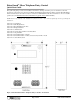
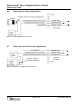
EntraGuard® Silver Telephone Entry Control Quick Start Guide Figure 2: Silver and Optional PXL-5xx Board Placement NOTE: For information on the optional PXL-500/PXL-510 board, see the PXL-500/PXL-510 Quick Start Guide (P/N 01918-001). Page 2 of 27 P/N: 01960-001 Rev.
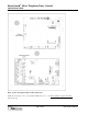
EntraGuard® Silver Telephone Entry Control Quick Start Guide Figure 3: The Silver Telephone Entry Controller NOTE: You must power down the unit before attempting to make or remove any connections. Failure to do so will damage the controller. Page 3 of 27 P/N: 01960-001 Rev.
EntraGuard® Silver Telephone Entry Control Quick Start Guide 1.
EntraGuard® Silver Telephone Entry Control Quick Start Guide 2.
EntraGuard® Silver Telephone Entry Control Quick Start Guide 3.
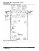
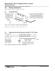
EntraGuard® Silver Telephone Entry Control Quick Start Guide 4.0 Wiring Instructions Refer to Figure 3 on page 3 for all wiring connections. 4.1 Terminal Blocks Figure 4: Connecting Wires and Removing Terminal Blocks NOTE: Screws on terminal blocks must be tightened securely. 4.2 Connecting the Earth Ground and the 12 VDC Power Figure 5: Earth Ground and 12 VDC Power Connections Page 7 of 27 P/N: 01960-001 Rev.
EntraGuard® Silver Telephone Entry Control Quick Start Guide 4.3 Connecting a Door Status Input Each EntraGuard Silver controller is shipped with an installation kit including all necessary terminal blocks and transorbs. One of these terminal blocks has a jumper across pins 1 and 2. This terminal block is designated for use on TB-4. If a door switch is not used on the controller, this jumper prevents a continuous door open status alarm from being received by the controller.
EntraGuard® Silver Telephone Entry Control Quick Start Guide 4.5 Connecting a General Purpose Input The general-purpose input is used in conjunction with the programmable input/output feature of the Doors access control software. There are two possible uses for the general-purpose input.
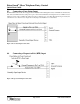
EntraGuard® Silver Telephone Entry Control Quick Start Guide 4.6 Connecting an Alarm Output Relay Figure 10: Alarm Output Relay Connections 4.7 Connecting a Fail-Safe Lock Output Relay Figure 11: Fail-Safe Lock Output Relay Connections Page 10 of 27 P/N: 01960-001 Rev.
EntraGuard® Silver Telephone Entry Control Quick Start Guide 4.8 Connecting a Fail-Secure Lock Output Relay Figure 12: Fail-Secure Lock Output Relay Connections Page 11 of 27 P/N: 01960-001 Rev.
EntraGuard® Silver Telephone Entry Control Quick Start Guide 5.
EntraGuard® Silver Telephone Entry Control Quick Start Guide Figure 14: Single Phone Line for a Multiple EntraGuard Silver Unit Network Page 13 of 27 P/N: 01960-001 Rev.
EntraGuard® Silver Telephone Entry Control Quick Start Guide 5.2 Between EntraGuard Network and Host Computer A communication link between the EntraGuard network and the host computer is provided via one of two ways. • • using the phone line connected to TB-15 using the RS-232 serial port NOTE: In order for monitor mode to work, the RS-232 serial port method must be used (see Section 5.2.2 on page 15). 5.2.
EntraGuard® Silver Telephone Entry Control Quick Start Guide 5.2.2 RS-232 Serial Port Using the RS-232 serial port for communication between the EntraGuard unit and the host computer may be done one of two ways: • • by direct connect through an external modem. For either of these options, the INT_MODEM J11 jumper should not have a jumper across it. Verify there is no jumper set across J11 (see Figure 3 on page 3) when using the RS-232 serial port for communication.
EntraGuard® Silver Telephone Entry Control Quick Start Guide 5.2.2.1 Direct Serial Connection – Controller to PC To make the connection between the EntraGuard master controller and the host computer you will use one cable. • • If the host computer has a male DB-9 connector on the serial port, you must use a Keri Systems KDP-252 cable or create a cable according to the drawing in Figure 16.
EntraGuard® Silver Telephone Entry Control Quick Start Guide 5.2.2.2 Modem to Controller To make the connection between the master controller and the host computer you will use two cables: one between the host computer and its modem (see Section 5.2.3 on page 19), and one between the master controller and its modem. • • • If the modem has a female DB-25 connector, you must use a Keri Systems KDP-336 cable or create a cable as shown in Figure 18.
EntraGuard® Silver Telephone Entry Control Quick Start Guide 5.2.2.3 • • Modem Cable Connection An adapter cable is provided, when needed, with a modem purchased from Keri Systems. Connect the adapter cable between the modem and the KDP-336 cable as shown in side A of Figure 20. To use the KDP-929M cable see side B of Figure 20. Figure 20: Modem Cable Connection Page 18 of 27 P/N: 01960-001 Rev.
EntraGuard® Silver Telephone Entry Control Quick Start Guide 5.2.3 Modem to PC Serial Connection Keri Systems does not provide this cable. It is an off-the-shelf item from any computer supplier or electronics store, and its configuration is dependent upon the configuration of the serial port on the host computer. Based on the serial port, there are four possible cables.
EntraGuard® Silver Telephone Entry Control Quick Start Guide Figure 23: Modem/DB-9M to PC/DB-9F PC Serial COM Port Connection Figure 24: Modem/DB-9M to PC/DB-25F PC Serial COM Port Connection Page 20 of 27 P/N: 01960-001 Rev.
EntraGuard® Silver Telephone Entry Control Quick Start Guide 5.3 Network Communication 5.3.1 RS-485 Access Control Network Connection The following figure shows how to connect more than one controller to the access control network. Figure 25: RS-485 Network Connections Page 21 of 27 P/N: 01960-001 Rev.
EntraGuard® Silver Telephone Entry Control Quick Start Guide 6.0 Powering the Controller for the First Time NOTE: Verify the earth ground has been connected at pin 3 of TB-2 before turning the power on for the first time. 6.1 Verify the 12 VDC Supply Voltage To verify the 12 VDC supply voltage: 1. 2. 3. 4. 5. Turn system power on. Set the DVM to a DC volt scale capable of reading 12 VDC. Place the Red DVM lead on Pin 1 of TB-2. Place the Black DVM lead on Pin 2 of TB-2. Check the DVM reading.
EntraGuard® Silver Telephone Entry Control Quick Start Guide 7.1 Set Unit Address The controller’s address may only be set through the Reset Menu. Once you have performed the necessary steps to reach the Reset Menu as described above, if the EntraGuard Silver unit has an alpha/numeric keypad, the keypad will default to the numeric keypad (if the alpha keypad is lit instead, press the #/A key to return to numeric mode). To set the desired operating address for the controller, press 1 on the keypad.
EntraGuard® Silver Telephone Entry Control Quick Start Guide Figure 29: Not Initialized Unit Warning NOTE: Any time the “Not Initialized Unit Warning” appears on the LCD display, the unit needs a Doors update. Figure 30: EntraGuard Silver Default LCD Display NOTE: The default display will remain until a message banner has been created (for instructions on how to create a message banner see the Doors Users Guide - P/N 01914-100).
EntraGuard® Silver Telephone Entry Control Quick Start Guide 7.2 Clear the Controller’s RAM When turning system power on for the first time, the controller’s memory needs to be cleared of any spurious information that may be in the RAM. If you changed the controller address, the memory is automatically cleared. However, if you did not change the address, you will need to clear the controller’s RAM separately. From the Reset Menu (see Figure 26 on page 22), press 2 to Clear Memory.
EntraGuard® Silver Telephone Entry Control Quick Start Guide 8.0 General Information on Inputs A controller input detects a state change generated by a device outside the controller that may prompt a response from the controller. Input devices that generate a state change may be normally closed or normally open. This section provides a brief description of normally closed versus normally open inputs. 8.1 Normally-Closed A normally closed input device continually keeps a circuit active or complete.
EntraGuard® Silver Telephone Entry Control Quick Start Guide 10.0 Contact Keri Systems Keri USA Keri UK, Ireland, Europe 2305 Bering Drive San Jose, CA 95131 Unit 17 Park Farm Industrial Estate Ermine Street Buntingford Herts SG9 9AZ UK Telephone: (800) 260-5265 (408) 435-8400 Telephone: + 44 (0) 1763 273 243 Fax: (408) 577-1792 Fax:+ 44 (0) 1763 274 106 Web: www.kerisys.com Web:www.kerisystems.co.uk E-mail: sales@kerisys.com techsupport@kerisys.com E-mail:sales@kerisystems.co.