
User Manual

Wiegand Elevator Control Panel
2305 Bering Drive 01942-001 Rev. D
San Jose, CA 95131 USA
(800) 260-5265 (408) 435-8400 FAX (408) 577-1792
Web: www.kerisys.com E-mail: sales@kerisys.com Page 14 of 24
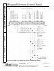
Quick Start GuideLC-502W/LC-508W
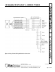
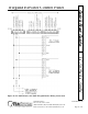
All other reader connections to the remaining LC-502W panels are made per the following rules.
1. The reader data lines must be daisy-chained from the master elevator panel to all other elevator
panel data inputs – Data 0 to Pin 1 of TB-5 and TB-6 and Data 1 to Pin 7 of TB-5 and TB-6 on
the LC-502W panels.
2. The reader ground line must be daisy-chained from the master elevator panel to all other
elevator panel antenna grounds to provide a standard ground reference for all panels – Pin 4 of
TB-5 and TB-6 on the LC-502W panels.
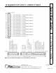
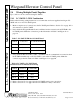
Make the data line daisy-chain connections per the information in Table 5 and Figure 9 on page 15.
Table 4: Distribution Amplifier to
Master Elevator Panel
Amplifier WDA-TB-2 Panel TB-5
Pin 1 Pin 1
Pin 2 Pin 2
Pin 3 Pin 3
Pin 4 Pin 4
Pin 5 Pin 5
Pin 6 Pin 6
Pin 7 Pin 7
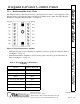
Table 5: Master Elevator Panel to Slave
Elevator Panels
Master Panel TB-5 Slave Panel TB-5 or TB-6
Pin 1 Pin 1
Pin 4 Pin 4
Pin 7 Pin 7